
Related Manuals for Sungrow SG2KTL-S


Summary of Contents for Sungrow SG2KTL-S
- Page 1 User Manual SG2KTL-S/SG2K5TL-S/SG3KTL-S/SG3K6TL-S/SG4KT L-S/SG3KTL-D/SG3K6TL-D/SG4K6TL-D/SG5KTL-D PV Grid-Connected Inverter SG2_2.5_3_3.6_4_4.6_5KTL-UEN-Ver20-201501 Version:2.0...
- Page 3 PV plant system. Purpose The purpose of this manual is to provide detailed product information and instructions for the use of SG2KTL-S, SG2K5TL-S SG3KTL-S, SG3K6TL-S, SG4KTL-S, SG3KTL-D, SG3K6TL-D, SG4K6TL-D and SG5KTL-D PV grid-connected inverter. Related Documents The manual cannot include complete information about the PV system.
- Page 4 Symbols Explanation This manual contains important safety and operational instructions that must be accurately understood and followed during the installation and maintenance of the equipment. To ensure optimum use of this manual, note the following explanations of symbols used. DANGER indicates a hazard with a high level of risk which, if not avoided, will result in death or serious injury.
- Page 5 Read over the user manual before any work on the inverter! The installation and service of the inverter unit can only be performed by qualified personnel.
-
Page 6: Table Of Contents
Contents About This Manual ................I 1 Safety Instructions ..............1 IMPORTANT SAFETY INSTRUCTIONS ..............1 2 Product Introduction ............... 6 Intended Usage ...................... 6 Product Description ....................7 2.2.1 Product Appearance ....................7 ... - Page 7 5.4.1 AC Side Requirements ..................28 5.4.2 Assembling AC Cables to Connector .............. 29 5.4.3 AC Wiring Procedure ..................... 30 Connecting Inverter to PV Arrays ..............32 5.5.1 PV Inputs Configuration ..................32 5.5.2 Assembling DC Cable to Connector ..............
- Page 8 9.1.2 Troubleshooting of Faults in the smartphone application interface .. 55 Fault Repair ......................59 Routine Maintenance ..................59 10 FAQ for SolarInfo WiFi Installation and Configuration ..60 10.1 FAQ Index Table ....................60 ...
-
Page 9: 1 Safety Instructions
1 Safety Instructions 1.1 IMPORTANT SAFETY INSTRUCTIONS SG2K5TL-S, SG3KTL-S, SG3K6TL-S, SG4KTL-S, SG4K6TL-D and SG5KTL-D inverter are designed and tested in accordance with the international safety requirements. But as with all electrical and electronic equipments, certain precautions should be observed during installation, operation and maintenance work. There is a risk of inverter damage or personnel injury! Various interfaces are provided on the bottom of the inverter. - Page 10 1 Safety Instructions User Manual Before Installation There is a risk of injury if the product is mishandled! Always follow the instructions in the manual when moving and positioning the inverter. The weight of the equipment can cause injuries, serious wounds, or bruising if mishandled.
- Page 11 User Manual 1 Safety Instructions During Inverter Operation There is a risk of inverter’s damage or personal injury! Do not disconnect DC connectors while the inverter is under AC load! First de-energize the equipment from the dual power sources and then verify that there is no voltage existing.
- Page 12 1 Safety Instructions User Manual There is a risk of inverter damage or personal injury due to incorrect service work! Always keep in mind that the inverter is power supplied by dual power source: PV arrays and utility grid. Before any service work, observe the following procedures. Disconnect the inverter from the utility grid side first and then PV arrays;...
- Page 13 User Manual 1 Safety Instructions Others The selected country settings can be changed by qualified personnel only! Alternation of the country settings may cause a breach to the type-certificate marking All safety instructions, warning labels and nameplate on the inverter body: must be clearly visible;...
-
Page 14: 2 Product Introduction
2 Product Introduction 2.1 Intended Usage SG2K5TL-S, SG3KTL-S, SG3K6TL-S, SG4KTL-S, SG4K6TL-D and SG5KTL-D (They will be referred to as inverter hereinafter unless otherwise specified), single-phase without transformer string inverter, is a crucial unit between the PV arrays and the utility grid in the small-scaled PV power system. -
Page 15: Product Description
User Manual 2 Product Introduction Item Description Remark Utility grid TT, TN For TT utility grid, N line voltage to ground must be less than 30V. Any other or additional usage other than the intended usage is not permitted. Inverter only accepts PV modules of Protection Class II as its input. Inverter may only be connected to utility grid via distribution board. -
Page 16: Dimensions And Weight Of Inverter
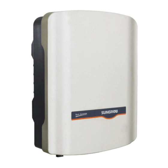
Fig. 2-3 Dimensions of Inverter Tab. 2-1 Dimensions Value Type W(mm) H(mm) D(mm) Net weight(kg) SG2KTL-S/SG2K5TL-S/S G3KTL-S/SG3K6TL-S/ SG4KTL-S SG3KTL-D/SG3K6TL-D/ SG4K6TL-D/SG5KTL-D 2.2.3 LED Indicator Panel As a human-computer interaction interface, the LED indicator on the inverter front panel indicates the working statues of the inverter. -
Page 17: Technical Description
User Manual 2 Product Introduction Tab. 2-2 Description of LED Indicator State Description Non-running Non-fault (For Green& Flicker once in turn every 1 example, the inverter is in standby second state.) Flicker once every 0.2 seconds to 2 seconds ( The greater the Green Inverter is running. -
Page 18: Functions Description
Inverter provides various parameters configuration for optimal operation. You can choose the type of country by APP, if you need a more professional setting, please contact Sungrow. Communication interface WiFi module for connecting other monitoring devices to the PV system is included. -
Page 19: Temperature-Related Power Derating
User Manual 2 Product Introduction − DC over-voltage protection − over-current protection − over-temperature protection 2.3.3 Temperature-related Power Derating The following graph shows the automatic reduction in output power in relation to ambient temperature. - Page 20 2 Product Introduction User Manual...
- Page 21 User Manual 2 Product Introduction *The derating curve shown in the graph above is obtained by the test in high temperature environmental chamber. −...
-
Page 22: 3 Unpacking And Storage
Do not dispose of the original packaging. It is the best choice to store the inverter in the original packaging. Fig. 3-1 Single Inverter Packing * The dimensions shown in the image here is for reference only. Item SG2KTL-S/SG2K5TL-S/SG3KTL-S/ 500mm 210mm 385mm SG3K6TL-S/SG4KTL-S... -
Page 23: Identifying Inverter
They provide information on the type of inverter, the most important specifications, marks of certification institutions, website and serial number which are available and identified by Sungrow. Fig. 3-2 Nameplate of Inverter * Image shown here is for reference only. Actual product you receive may differ. -
Page 24: Delivery Contents
3 Unpacking and Storage User Manual 3.3 Delivery Contents Fig. 3-3 Delivery Contents Item Description Inverter unit It is used to mount the inverter onto the wall Expansion bolts for fastening the backplate onto concrete wall Fastener set for installing the inverter onto metal frame PV input connectors, including positive and negative connectors WiFi, for wireless communication(Optional) Quick user manual and CD... -
Page 25: Storage Of Inverter
If there is more than one inverter to be stored, the maximum layers for original paper packaging are five. After long-term storage or decommissioning, local installer or Service Dept. of Sungrow should perform a comprehensive test before connecting the inverter into PV power system. -
Page 26: 4 Securing Inverter To The Wall
4 Securing Inverter to the Wall 4.1 Selecting Installation Location Selecting an optimal installation location for the inverter is decisive for its operating safety as well as its expected efficiency and service life. 1. Take the load capacity of the wall into account. The wall (such as concrete wall or metal structure) should be strong enough to hold the weight of the inverter over a long period of time. - Page 27 User Manual 4 Securing Inverter to the Wall 5. Install the unit at eye level for easy button operation and display read. 6. It is suggested that the inverter be installed vertically with upside up for good heat dissipation. 7. Never install the inverter horizontally, or with a forward tilt or with a backward tilt or even with upside down.
- Page 28 4 Securing Inverter to the Wall User Manual 9. The ambient temperature should Max. ambient temperature: range from -25°C to 60°C. The power +60°C output will reduce when the ambient temperature exceeds 45°C. Min. ambient temperature: 10. The relative humidity of chosen -25°C installation site should never exceed 100%.
-
Page 29: Moving Inverter To Installation Site
User Manual 4 Securing Inverter to the Wall 13. Do not install the inverter in a closed cabinet. Otherwise, the inverter will not operate normally. 14. Do not install the inverter where children can reach. 15. Do not install the inverter in residential area. Noise can be produced during the running of the inverter and may affect your daily life. - Page 30 4 Securing Inverter to the Wall User Manual Fig. 4-1 Fastener(unit: mm) Fig. 4-2 Dimensions of Expansion Bolt Set for Concrete Wall (unit: mm) Fig. 4-3 Dimensions of Fastener Set for Metal Frame(unit: mm) Please select the appropriate length of the expansion screw according to the thickness of the wall insulation layer.
- Page 31 User Manual 4 Securing Inverter to the Wall 2. Fasten the screws with appropriate torque. Screw a M5 screw onto the chosen concrete wall. Step 3 In order to avoid electrical shock or other injury, inspect if there is electricity or plumbing installation before drilling holes.
- Page 32 4 Securing Inverter to the Wall User Manual The lock is an optional accessory. Users need to purchase it. Metal Frame Remove the supplied backplate from the packaging. Step 1 WiFi connection. (If you purchase WiFi module) Step 2 Screw a M5 screw onto the chosen mental frame. Step 3 If the shape of the metal frame doesn’t fit the holes on the backplate, you need to re-drill holes on the backplate at appropriate position according...
- Page 33 User Manual 4 Securing Inverter to the Wall...
-
Page 34: 5 Electrical Connection
5 Electrical Connection 5.1 General Safety Instruction Once the inverter is firmly attached to the appropriate location, it can be connected into the PV power system. Prior to any electrical connection, keep in mind that the inverter has dual power supplies. -
Page 35: Terminals Description
User Manual 5 Electrical Connection 5.2 Terminals Description All electrical terminals are located at the bottom of unit. Fig. 5-1 shows the connection area. Enough space should be kept for electrical connection at the bottom of the inverter when choosing the installation site. Fig. -
Page 36: Connecting Inverter To Ac Grid
5 Electrical Connection User Manual Fig. 5-2 Electrical Connection Diagram Item Description Remark Used as a protective device during electrical AC circuit breaker connection. User equips this device according to the maximum output voltage and current. Nominal line-to-neutral voltage of the utility grid is Utility grid 230V. -
Page 37: Assembling Ac Cables To Connector
AC Side Circuit Breaker An independent two-pole circuit breaker for the inverter must be installed at the output side to ensure that the inverter can be securely disconnected under load. Inverter Type Specification Recommended of AC Circuit Breaker SG2KTL-S SG2K5TL-S SG3KTL-S SG3K6TL-S SG4KTL-S... -
Page 38: Ac Wiring Procedure
5 Electrical Connection User Manual The grid impedance of the AC cable must correspond to the specification to avoid unintended disconnection from the grid or derating of the output power. The cable cross-sectional areas and recommended value are shown in the following table, avoiding power loss in the cables of more than 1% of the nominal power. - Page 39 User Manual 5 Electrical Connection Description Remark Accepted cable external diameter ranges from Protective layer 10mm to 14mm. Length of insulation to be 18 mm stripped off Insulation layer Lead the AC cable through the Thread-Lock Sealing Nut, and the cable gland. Step 4 Fix all cables to the corresponding terminals according to markings on the Step 5...
-
Page 40: Connecting Inverter To Pv Arrays
5 Electrical Connection User Manual Make sure the AC and DC circuit breaker are disconnected. Step 9 Connect phase cable and “N” cable to AC circuit breaker. Step 10 Connect AC circuit breaker to utility grid. Step 11 Make sure all AC cables are firmly installed. Step 12 5.5 Connecting Inverter to PV Arrays Lethal voltage exists! - Page 41 User Manual 5 Electrical Connection two PV inputs can be configured in independent mode or parallel mode. PV Configuration Mode-Independent Mode For independent mode, the two PV inputs work independently, each with its own MPPT. Therefore the two PV inputs can be different from each other in PV module types, numbers of PV panels in PV string, tilt angles and orientation angle of PV modules.
- Page 42 SG3K6TL-S 3900 W 600V SG4KTL-S 4300 W 600V To avoid input power unbalance of the two inputs or input load-restriction, ensure the two PV input cables are of the same model. • SG2KTL-S/SG2K5TL-S/ SG3KTL-S As shown in the following diagram.
-
Page 43: Assembling Dc Cable To Connector
User Manual 5 Electrical Connection Total DC Input Open-circuit Short-circuit Type Power Limit Voltage Limit Current Limit SG2KTL-S 2300W 600V SG2K5TL-S 2800W 600V SG3KTL-S 3300 W 600V 5.5.2 Assembling DC Cable to Connector All DC cables are equipped with water-proof direct plug-in connectors, which match the DC terminals at the bottom of the inverter. - Page 44 5 Electrical Connection User Manual The DC cables must be flexible wires. DC Connector Assembling Procedure: Make sure that all the DC and AC cables to the inverter are not live before you start the electrical work. Strip off 7mm insulation layer from all Step 1 DC cables.
-
Page 45: Dc Wiring Procedure
User Manual 5 Electrical Connection For further assembly and connection instruction, please visit the webpage of the device manufacturer. Make sure the connection cable of PV string for the correct polarity. Step 6 The inverter will not function properly if the DC polarities are reversed. Disconnect the DC switch. -
Page 46: Grounding Of Inverter
5 Electrical Connection User Manual 480.0 Check the positive and negative polarity of the PV cells. After confirmation, you can insert the DC connectors into the input terminals on the bottom of the inverter. For the same MPPT, reverse connection of a single string is prohibited. A permanent failure of the system or inverter may follow if otherwise. -
Page 47: Second Protective Earth Terminal
User Manual 5 Electrical Connection Where there is only one inverter in the PV power system, connect the “PE” cable to the installation ground. 5.6.1 Second Protective Earth Terminal The inverter is equipped with second protective earth terminal as specified in EN 50178. -
Page 48: 6 Communication
Communication 6.1 Communication System communication connection between inverter mobile smartphone/router can be established via SolarInfo WiFi. If you have problems, please refer to "10 FAQ for SolarInfo WiFi Installation and Configuration". 6.2 Distance between inverter smartphone/router 6.2.1 Linear distance If there are no obstructions between the inverter and smartphone/router, the maximum linear distance between them can be 150m. -
Page 49: Inverter And Smartphone / Router On Different Floors
User Manual 6 Communication Impacts of common materials on the wireless signal Wireless signal Material Possible Environment strength Wood Compartment Plaster\Asbestos Wall Glass Window Water Aquarium, pool Brick wall Partition Marble Floor Reinforced Floor panels, wall concrete Metal Iron sheet cordless smartphones, microwave... -
Page 50: Inverter And Smartphone / Router On The Same Floor, In Different Rooms
6 Communication User Manual Image shown here is for reference only. The inverter can be installed indoors or outdoors. 6.2.3 Inverter and smartphone / router on the same floor, in different rooms... -
Page 51: Solarinfo Home App
User Manual 6 Communication Keep the inverter in parallel with the external antenna of the router. The WiFi module can not be blocked by metal. In order to avoid wireless electromagnetic interference, please keep the inverter away from equipment such as cordless smartphones, microwave ovens and so on. - Page 52 User Manual For other smartphone(Android) The address for downloading SolarInfo Home APP is https://play.google.com/store/apps/details?id=com.sungrow.home.or Http://www.solarinfobank.com/app/SolarInfoHome_v1.0.apk.You can also use your smartphone to scan the following OR codes to download and install it. Search SolarInfo Home in your PlayStore to download and install it.
- Page 53 User Manual 6 Communication Search solarinfo home Download Install To perform the operations in the following sections, make sure the distances between the smartphone and the inverters, inverters and the routers are within the valid range. SolarInfo Home APP supports two kinds of operation:“Remote [Login]”and “[Direct visit]”.
-
Page 54: Solarinfo Home App Online Registration
6 Communication User Manual 6.3.2 SolarInfo Home APP Online Registration Slide left Slide left SolarInfo Home NOTE Please enter your e-mail account and the password. Slide right(Yes) ******* 123456 Inverter Next Nameplate Submit Press HOME button... -
Page 55: Check The Running Information And Connect Inverter To Your Router In "[Direct Visit]"Mode
User Manual 6 Communication 6.3.3 Check the running information and connect inverter to your router in “[Direct visit]”mode. 1. Check the running information... - Page 56 6 Communication User Manual 2.Select the country you are in and connect inverter to your router Click and select the country you are in Setting NOTE Please do not name your router started with "SG". Otherwise you cannot find it. Select your router Enter router’s password...
-
Page 57: Check The Running Information In "Remote [Login]"Mode
User Manual 6 Communication 6.3.4 Check the running information in “Remote [Login]”mode. If you want to check the running information via Internet in “Remote [Login]” mode, please follow the steps below. Change Off to On Select your router Settings Press HOME button Press... -
Page 58: 7 Commissioning
Commissioning 7.1 Verify before Commissioning Before starting up the inverter, you should check the following items. 1. Inverter unit is accessible for operation, maintenance and service. 2. Re-check whether the inverter is firmly secured to the wall. 3. Room for ventilation is provided for one inverter or more than one inverter. 4. - Page 59 User Manual 7 Commissioning State Description Non-running Non-fault (For Green& Flicker once in turn every 1 example, the inverter is in standby second state.) Flicker once every 0.2 seconds to 2 seconds ( The greater the Green Inverter is running. inverter current power, the faster the green light flashing)...
-
Page 60: 8 Disconnecting, Dismantling And Disposing Of The Inverter
8 Disconnecting, Dismantling and Disposing of the Inverter 8.1 Disconnecting the Inverter For maintenance or other service work, the inverter must be switched off. Proceed as follows to disconnect the inverter from the AC and DC power source. Lethal voltages or damages to the inverter will follow if otherwise. Disconnect the external AC circuit breaker and prevent it from reconnecting. -
Page 61: Dismantling The Inverter
User Manual 8 Disconnecting, Dismantling and Disposing of the Inverter 8.2 Dismantling the Inverter Refer to Chapter 6 for the inverter disconnection of all cables in reverse steps. There is a risk of burn injuries and electric shock! Wait at least 10 minutes after disconnecting the inverter from the utility grid and the PV input before touching any inner live parts. -
Page 62: 9 Troubleshooting And Maintenance
4. Check whether the voltage of DC input exceeds the inverter start-up voltage. 5. If all above conditions are OK, please contact Sungrow. Should you have any questions in operating the inverter, please contact Telesmartphone: +86 551 6532 7817. -
Page 63: Troubleshooting Of Faults In The Smartphone Application Interface
3. If the grid voltage is within the permissible range, contact Sungrow Service Dept.. 1. This is a short-term fault due to grid Grid transient voltage condition. Wait a moment for inverter recovery. - Page 64 Islanding 3. Check whether grid is not in service. 4. If all conditions are OK and this fault still occurs in the LCD screen, contact Sungrow Service Dept.. The DC component of AC 1. Wait a moment for inverter recovery.
- Page 65 3. If the grid voltage is within the permissible range, contact Sungrow Service Dept.. 1. Check the grid frequency. 2. If the grid frequency exceeds the permissible Auxiliary DSP detects grid range of inverter protection parameters, ask frequency exceeds set utility grid company for solution.
- Page 66 Fans are defective cables. Check whether the fan duct has been blocked. If not, replace fans. self-detection Wait a while. Contact Sungrow if device is still anomaly warn in self-detection warn state. 1. Stop the inverter and disconnect the AC &...
-
Page 67: Fault Repair
Check whether the configuration of PV is in the range indicated in the specification. If the fault DC power is too high occurs repeatedly, contact Sungrow Service Dept.. 9.2 Fault Repair If the inverter can not work normally, you can contact the service provider for troubleshooting. -
Page 68: 10 Faq For Solarinfo Wifi Installation And Configuration
10 FAQ for SolarInfo WiFi Installation and Configuration 10.1 FAQ Index Table Title 1001 Configurable terminal devices cannot find WiFi after installation 1002 Router password is correct or not 1003 Cannot find the assigned Router 1004 Communication strength is weak (Installation notice) 1005 User performs certain advanced operation to the Router 1006... - Page 69 User Manual 9 FAQ for SolarInfo WiFi Question description: configuration end cannot find WiFi after installation Solution: 1) Check if the device begins operation 2) Check if WiFi is installed correctly 3) The configuration end and WiFi should not be too far away. Move them together to check if the search can be done.
- Page 70 9 FAQ for SolarInfo WiFi User Manual No. 1004: Communication strength is weak (Installation notice) Applicable: All Fault type: Improper installation method Question description: Signal strength bar is less than one Solution: 1) Make sure the device is at least 30CM higher than the floor 2) Make sure the device is at least 40CM from the wall 3) Make sure the device is installed internally between the PC cell or installation frame and the ground...
- Page 71 User Manual 9 FAQ for SolarInfo WiFi Prevention measure: operate as described in the figure above. No. 1005: User performs certain advanced operation to the Router Applicable: All routers Fault type: Improper operation Question description: user perform some advanced settings to the Router, for example, MAC address filtering, IP range limitation, access number limitation, SSID limitation, DHCP enable, hidden of the Router SSID or other advanced settings.
- Page 72 9 FAQ for SolarInfo WiFi User Manual Check the “Enable DHCP Server”; set the “DHCP IP Address Range” as wide as possible, otherwise the accessed user numbers may decrease and cannot connect to WIFI. “Wireless filter policy” is to set which devices are allowed to be connected to the Router.
- Page 73 User Manual 9 FAQ for SolarInfo WiFi No. 1006: 2 Routers nearby have the same SSID Applicable: All Fault type: 2 routers with the same name Question description: two routers nearby have the same router name. Cannot connect to the target Router even if the password is correct Solution: Change the SSID of the Router that can be changed Prevention measure: User confirmation No.
- Page 74 9 FAQ for SolarInfo WiFi User Manual No. 1009: Router SSID contains special characters and cannot connect to WiFi Applicable: All Fault type: WiFi software bug Question description: Router SSID contains special characters and cannot connect to WiFi Solution: modify WiFi software Prevention measure: modify WiFi firmware No.
- Page 75 User Manual 9 FAQ for SolarInfo WiFi No. 1011: Impacts of materials on the wireless signal Fault type: interference Question description: wireless transmission device and impacts of materials on the Wireless signal Wireless signal Material Possible Environment strength Wood Compartment Plaster\Asbestos Wall Glass...
-
Page 76: 11 Appendix
11 Appendix 11.1 Technical Data 11.1.1 Single MPPT Inverter Data SG2KTL-S/ SG2K5TL-S Technical SG2KTL-S SG2K5TL-S Specifications Input Side Data Max. PV input power 2300W 2800W Max. PV input voltage 600V 600V Startup voltage 150V 150V Nominal input 345V voltage MPP voltage range 125…560V... - Page 77 User Manual 9 Appendix Technical SG2KTL-S SG2K5TL-S Specifications country’s grid standard) <3% (Nominal power) DC current injection <0.5% In >0.99@default value at nominal power Power factor (adj. 0.8 over-excited~0.8 under-excited) Protection Anti-islanding protection short circuit protection Leakage current protection DC switch...
- Page 78 9 Appendix User Manual Technical SG2KTL-S SG2K5TL-S Specifications Mounting method Wall bracket Weight SG3KTL-S/ SG3K6TL-S/ SG4KTL-S Technical SG3KTL-S SG3K6TL-S SG4KTL-S Specifications Input Side Data Max. PV input power 3300W 3900W 4300W Max. PV input voltage 600V 600V 600V Startup voltage...
- Page 79 User Manual 9 Appendix Technical SG3KTL-S SG3K6TL-S SG4KTL-S Specifications protection short circuit protection Leakage current protection Optional DC switch DC fuse Overvoltage Varistors protection System Data Max. efficiency 98.00% 98.00% 98.00% Max. European 97.50% 97.50% 97.50% efficiency Isolation method Transformerless Ingress protection IP65...
-
Page 80: Double Mppts Inverter Data
9 Appendix User Manual 11.1.2 Double MPPTs Inverter Data SG3KTL-D/SG3K6TL-D Technical SG3KTL-D SG3K6TL-D Specifications Input Side Data Max. PV input power 3300W 3900W Max. PV input voltage 600V 600V Startup voltage 150V 150V Nominal input 345V voltage MPP voltage range 125…560V 125…560V MPP voltage range for... - Page 81 User Manual 9 Appendix Technical SG3KTL-D SG3K6TL-D Specifications protection short circuit protection Leakage current protection Optional DC switch DC fuse Overvoltage Varistors protection System Data Max. efficiency 98.00% 98.00% Max. European 97.50% 97.50% efficiency Isolation method Transformerless Ingress protection IP65 rating Night power...
- Page 82 9 Appendix User Manual SG4K6TL-D/SG5KTL-D Technical SG4K6TL-D SG5KTL-D Specifications Input Side Data Max. PV input power 4900W 5400W Max. PV input voltage 600V 600V Startup voltage 150V 150V Nominal input 345V voltage MPP voltage range 125…560V 125…560V MPP voltage range for 220…520V 240…520V nominal power...
- Page 83 User Manual 9 Appendix Technical SG4K6TL-D SG5KTL-D Specifications protection Leakage current protection DC switch Optional DC fuse Overvoltage Varistors protection System Data Max. efficiency 98.00% 98.00% Max. European 97.50% 97.50% efficiency Isolation method Transformerless Ingress protection IP65 rating Night power <1 W consumption Operating...
-
Page 84: Exclusion Of Liability
Unforeseen calamity or force majeure The use of supplied software produced by Sungrow Power Supply Co., Ltd. is subject to the following conditions: Sungrow Power Supply Co., Ltd. assumes no liability for direct or indirect damages arising from the use of SolarInfo software. -
Page 85: About Us
The power rating of Sungrow products covers from several hundred watt to large mega-watt systems. The pursuit of Sungrow is to help our customers acquire stable and clean power with minimum cost, maximum reliability and enhanced safety. Contact Information Should you have any questions or queries about this product, please contact us through the following information. - Page 86 Sungrow Power Supply Co., Ltd. Add: No.1699 Xiyou Rd.,New & High Technology Industrial Development Zone, 230088,Hefei, P. R. China. Post Zip: 230088 Web: www.sungrowpower.com Tel: +86 551 6532 7834/6532 7845 E-mail: info@sungrow.cn Fax: +86 551 6532 7856 Specifications are subject to changes without advance notice.
Need help?
Do you have a question about the SG2KTL-S and is the answer not in the manual?
Questions and answers
Sungrow Invertor SG5KTL-D is compatible with which residential solar batteries?