Sungrow SG2K-S User Manual
Pv grid-connected inverter
Hide thumbs
Also See for SG2K-S:
- User manual (95 pages) ,
- Quick user manual (93 pages) ,
- User manual (79 pages)

Subscribe to Our Youtube Channel
Related Manuals for Sungrow SG2K-S


Summary of Contents for Sungrow SG2K-S
- Page 1 User Manual SG2K-S / SG2K5-S / SG3K-S / SG3K-D / SG5K-D Grid-Connected Inverter SG2_2.5_3_5K-UEN-Ver14-201805 Version:1.4...
-
Page 3: About This Manual
Documents must be stored carefully and be available at all times. All rights to the content of this manual are owned by Sungrow Power Supply Co., Ltd. (hereinafter “SUNGROW”). No part of this document can be modified, distributed, reproduced or published in any form or by any means without prior written permission from SUNGROW. - Page 4 Symbols Safety instructions will be highlighted with the following symbols. Symbol Explanation Indicates a hazard with a high level of risk that, if not avoided, will result in death or serious injury. Indicates a hazard with a medium level of risk that, if not avoided, could result in death or serious injury.
-
Page 5: Table Of Contents
Contents About This Manual ..............I Safety .................. 1 General Safety ................1 Inverter ..................2 Skills of Qualified Personnel ............3 Product Introduction ............4 Intended Use ................4 Inverter ..................5 Energy Meter (optional) ............. 7 Function Description ..............8 2.4.1 Basic Function ................ - Page 6 5.3.1 AC Side Requirements .............. 22 5.3.2 Assembling the AC Connector ..........23 5.3.3 Installing the AC Connector ............24 PV Connection ................. 24 5.4.1 PV Input Configuration .............. 25 5.4.2 Assembling the PV Connector ..........26 5.4.3 Installing the PV Connector ............28 RS485 Connection ..............
- Page 7 Starting/Stopping the Inverter ..........45 Viewing the Error Record ............45 Setting the Time ..............45 Setting the Country ..............46 7.10 Viewing Device Info ..............48 Troubleshooting and Maintenance ........ 49 Troubleshooting ............... 49 8.1.1 For the Indicator Circle .............. 49 8.1.2 For the Errors on the App or LCD Screen .........
-
Page 9: Safety
1 Safety The inverter has been designed and tested strictly according to international safety regulations. Read all safety instructions carefully prior to any work and observe them at all times when working on or with the inverter. Incorrect operation or work may cause: ... -
Page 10: Inverter
1 Safety User Manual 1.2 Inverter There is a warning label on the inverter body. Disconnect the inverter from all the external power sources before service! Do not touch live parts until 10 minutes after disconnection from the power sources. There is a danger from a hot surface that may exceed 60°... -
Page 11: Skills Of Qualified Personnel
User Manual 1 Safety All the warning labels and nameplate on the inverter body: must be clearly visible; and must not be removed, covered or pasted. Risk of burns due to hot components! DO not touch the hot parts (such as heat sink) during operation. Only the buttons and the optional DC switch can be touched. -
Page 12: Product Introduction
Fig. 2-1 Application in a PV Power System Item Description Remarks Monocrystalline silicon, polycrystalline silicon PV strings and thin-film without grounding. SG2K-S, SG2K5-S, SG3K-S, SG3K-D and Inverter SG5K-D. Sungrow single-phase Measures the export power and communicate meter (optional) with the inverter via an RS485 connection. -
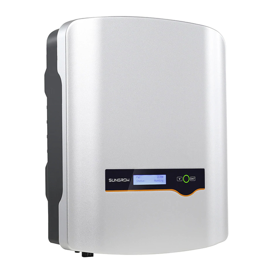
Page 13: Inverter
User Manual 2 Product Introduction Item Description Remarks Utility grid Grid earthing system types: TT, TN. Household load Devices that consume energy. For the TT utility grid, the N line voltage to ground must be less than 30 2.2 Inverter Appearance Fig. - Page 14 Tab. 2-1 Dimensions and Weight Type Weight W (mm) H (mm) D (mm) (kg) SG2K-S SG2K5-S SG3K-S SG3K-D / SG5K-D 11.5 LCD Display Panel The LCD display panel with a screen, an indicator and two buttons is on the front of the inverter.
-
Page 15: Energy Meter (Optional)
Tab. 6-2. 2.3 Energy Meter (optional) The SUNGROW Energy Meter is installed next to the main switch to detect the electrical measured values at the grid-connected point. It communicates with the inverter via an RS485 connection. The dimensions are shown below. -
Page 16: Function Description
Parameter configuration Inverter provides various parameter configurations for optimal operation. You can set the country via the SolarInfo Home App or SolarInfo Bank server, if you need a more professional setting, please contact Sungrow. Communication interface You can choose the RS485 terminal for connecting a communication module to the PV system, such as Wi-Fi module. -
Page 17: Reactive Power Regulation
User Manual 2 Product Introduction Mode Explanation DRM6 The export power to the grid is no more than 50% of the rated power. DRM7 The export power to the grid is no more than 75% of the rated power. The export power to the grid is 100% of the rated power, but subject DRM8 to the constraints from other active DRMs. -
Page 18: Unpacking And Storage
Check the delivery contents for completeness according to the packaging list. Contact SUNGROW or the distributor in case of any damaged or missing components. It is the best choice to store the inverter in the original packaging. So, do not dispose of it. - Page 19 Fig. 3-2 Nameplate of Inverter * The image shown here is for reference only. The actual product you receive may differ. Item Description Item Description SUNGROW logo and product Marks certification type institutions Barcode, company name and Technical data origin Tab.
-
Page 20: Delivery Contents
3 Unpacking and Storage User Manual 3.3 Delivery Contents Standard Delivery Wall-mounting bracket Documents Inverter (x1) M4x16 screw set Wi-Fi module Communication connector PV connector set M4x10 screw set (x5) AC connector set Fig. 3-3 Delivery Contents The documents include the Quick User Manual, 1 CD, quality certificates, packaging list and product test reports. -
Page 21: Storage Of Inverter
User Manual 3 Unpacking and Storage 3.4 Storage of Inverter If you do not install the inverter immediately, choose an appropriate location to store it. Store the inverter in the original packaging with the desiccant inside. The storage temperature should be always between -30° C and +85° C, and the storage relative humidity should be always between 0 and 100 %. -
Page 22: Mechanical Mounting
4 Mechanical Mounting 4.1 Safety during Mounting Make sure there is no electrical connection before installation. In order to avoid electric shock or other injury, be sure there is no electricity or plumbing installations before drilling holes. Risk of injury due to improper handling ... - Page 23 User Manual 4 Mechanical Mounting Do not install the inverter in the living area or bedrooms. The noise during its operation may affect daily life. The location should be not accessible to children. The ambient temperature and relative humidity should meet the following requirements.
-
Page 24: Installing The Inverter
4 Mechanical Mounting User Manual Place at eye level for easy Install vertically for good heat viewing: dissipation. Never install the inverter horizontally, or with a forward tilt or with a backward tilt or even with upside down. The horizontal installation could result in damage to the inverter. - Page 25 User Manual 4 Mechanical Mounting Self-tapping screw M6 Expansion tube Fender washer Spring washer Place wall-mounting 143.5 mm bracket to the wall and adjust it 123 mm until it is in a horizontal position. Mark the positions. 73.5 mm 113.5 mm 160 mm Drill holes and install the wall-mounting bracket.
-
Page 26: Installing The Energy Meter
The following figure takes the Wi-Fi module as an example. 4.4 Installing the Energy Meter The SUNGROW Energy Meter should be installed between the grid and the load. It supports a 35 mm DIN-rail installation, as shown in the following figure. Single-phase Energy Meter Three-phase Energy Meter Fig. -
Page 27: Electrical Connection
5 Electrical Connection Prior to any electrical connections, keep in mind that the inverter has dual power supplies. It is mandatory for the technical personnel to wear personal protective equipments (PPE) during the electrical work. Danger to life due to a high voltage inside the inverter ... -
Page 28: Terminal Description
5 Electrical Connection User Manual Fig. 5-1 Electrical Connection Diagram Item Name Remarks -S series: one pair of PV terminals. PV strings -D series: two pairs of PV terminals. Wi-Fi module RS485 communication. Used as a protective device during electrical connection. -
Page 29: Grounding The Inverter
User Manual 5 Electrical Connection * Image shown here is for reference only. The actual product you receive may differ. Tab. 5-1 Terminal Descriptions Item Terminal Description MC4 terminals for PV inputs. PV terminals -S series: one pair of PV terminals. -D series: two pairs of PV terminals. -
Page 30: Grid Connection
The recommended specifications are as follows: Inverter Type Specification SG2K-S / SG2K5-S / SG3K-S / SG3K-D 25 A SG5K-D 32 A It is not allowed for several inverters to use the same AC circuit breaker. -
Page 31: Assembling The Ac Connector
User Manual 5 Electrical Connection 5.3.2 Assembling the AC Connector Lead the AC cable through the Remove the cable jacket by cable gland and the housing. 40 mm, and strip the wire insulation by 8-15 mm. 40 mm 8-15 mm Fully insert the conductors to the corresponding terminal and tighten the screws with... -
Page 32: Installing The Ac Connector
5 Electrical Connection User Manual 5.3.3 Installing the AC Connector Disconnect the AC circuit breaker and secure it against reconnection. Measure the voltage and frequency of the grid-connected point to ensure that they are within the specified range listed in “10.1 Technical Data”. Align the AC connector and the AC terminal and mate them together by hand until a “Click”... -
Page 33: Pv Input Configuration
PV input Inverter inside Total PV Input Open-circuit Short-circuit Type Power Limit Voltage Limit Current Limit SG2K-S 3000 W 600 V 12 A SG2K5-S 3200 W 600 V 12 A SG3K-S 4000 W 600 V... -
Page 34: Assembling The Pv Connector
5 Electrical Connection User Manual Prior to connecting the inverter to PV inputs, the specifications in the following table should be met: Open-circuit Short-circuit Total PV Input Type Voltage Limit Current Limit Power Limit (PV1 / PV2) (PV1 / PV2) SG3K-D 4000 W 600 V/600 V... - Page 35 User Manual 5 Electrical Connection The PV cables must be multi-stranded wires. To ensure the protection degree IP65, only use the connectors delivered or connectors with the same degree of protection. The requirements of PV cables are as follows. Cross-section Cable Diameter Max.
-
Page 36: Installing The Pv Connector
5 Electrical Connection User Manual 5.4.3 Installing the PV Connector Connect the inverter to PV strings according to the following procedure. (Optional) If you purchase the DC switch, rotate it to “OFF”. Optional Check the connection cable of the PV string for the correct polarity and that the open-circuit voltage does not exceed the inverter input limit of 600 V, even under the lowest operating temperature. -
Page 37: Rs485 Connection
For the pin definition and waterproof procedure, please contact SUNGROW. Failure to comply with the requirements of wiring or waterproof will void the warranty. 5.6 Meter Connection The SUNGROW single-phase energy meter should be installed next to the main switch. Solar switch Main Meter... -
Page 38: On The Meter Side
5 Electrical Connection User Manual 5.6.1 On the Meter Side For Single-phase Energy Meter Take out the communication connector, four M4x10 screws and washers from inverter’s packaging, and the meter (with 1-phase sensor) and cables from the meter’s packaging. Communication connector Power supply cable Meter RS485 cable Unscrew the swivel nut from the cable gland and remove the waterproof... - Page 39 User Manual 5 Electrical Connection Make sure that the CT clamp of 1-phase sensor is installed in the right direction: the arrow on the sensor must point away from the grid towards the load. For Three-phase Energy Meter Take out the communication connector, four M4x10 screws and washers from inverter’s packaging, and the meter and RS485 cable from the meter’s packaging.
-
Page 40: On The Inverter Side
5 Electrical Connection User Manual Strip the insulation from the power wires by 10 mm. Then connect the wires to the terminals on the Energy Meter, as shown below. (Cross-section: 10 mm to 25 mm Load side Grid side The line conductor L1 supplies power to the Energy Meter. At least the line conductor L1 and the neutral conductor must be connected to switch on the Energy Meter. -
Page 41: Drm Connection To An External Device
User Manual 5 Electrical Connection Insert the RJ45 plug into the left (Meter) port until it makes a clicking sound. external demand response enabling device connected, secure waterproof lid to the inverter bottom with four screws and then fasten the cable gland. 5.7 DRM Connection to an External Device The cable for connecting to the DRED is not included in the delivery. - Page 42 5 Electrical Connection User Manual Unscrew the swivel nut from the cable gland and remove the waterproof plug from the right inlet. Lead the cable through the cable gland then the right inlet. Use the Ethernet crimper to crimp the cable and carefully push all 8 unstripped colored wires into the RJ45 plug according to TIA/EIA 568B standard, as shown below.
-
Page 43: Commissioning
Commissioning Commissioning is essential for the system, which can protect it against fires, injury and electric shock. 6.1 Inspection before Commissioning Check the following items before starting the inverter: All the installation sites are convenient for operation, maintenance and service. Check and confirm that the inverter is firmly installed. -
Page 44: Commissioning Procedure
6 Commissioning User Manual 6.3 Commissioning Procedure Make sure all the above mentioned items meet the requirements. Connect the external AC circuit breaker. (Optional) Rotate the DC switch to “ON”. If there is sufficient sunlight, the inverter will enter the running state and start to feed AC power to the grid. -
Page 45: Lcd Operation
7 LCD Operation 7.1 Button Function Inverter offers two buttons with multiple functions. Please refer to the following table before any operation of the inverter. Tab. 7-1 Button function Button Operation Description Navigate up / down or change the setting values. ≤1.2 s Hereinafter referred to as “Touch ESC”. - Page 46 If the device is in standby mode for more than 10 minutes, please check: Whether the insolation is sufficient and the PV connection is correct. If no anomaly is found, disconnect the DC switch and the main switch to restart. If it still does not work, contact SUNGROW.
-
Page 47: Menu Structure
User Manual 7 LCD Operation Viewing the Active Error/Warning If the status on the main screen is “Error xxx”, Error Touch ENT to view the active error code. If the inverter is running with a warning, Touch ENT to view the active warning code. Warning Only one error or warning can be displayed on this screen. -
Page 48: Advanced Settings
7 LCD Operation User Manual Main Screen (Press ENT)→Menu→Run Info (Press ENT) Scroll pages by touching ENT / ESC. E-today: 20.0kWh Vpv1: 250.0V Vpv2: 244.4V E-total: 1999kWh Ipv2: 2.6A Ipv1: 2.9A Pac: 221.7W 2210W Meter Power: Grid Vtg: 221.7V Grid Frq: 50.0Hz Iac: 100%... - Page 49 User Manual 7 LCD Operation Touch ESC to choose the item and press ENT to enter the Volt-watt Single/Mul Prot. setting interface. 10 Min Over Vtg En. Grid Prot. Adj. Single/Multiple Protection Touch ESC to change the value and touch ENT to move the cursor. Confirm settings by pressing ENT.
- Page 50 Fig. 7-2 Volt-watt Response Curve (“AU” for example) Grid Protection Voltage Adjusting All Sungrow’s inverters are compliant with the standard AS/NZS 4777 related to grid protection requirements. In order to work with unstable grid, inverters are equipped with automatic protection voltage adjusting function (disable by default) and this mode is available to enable by the LCD setting.
-
Page 51: Zero-Export Setting
High line voltages may damage home appliances and Sungrow is not held responsible or liable for these issues. 7.5.3 Zero-export Setting Touch ENT / ESC to select and press ENT to confirm. -
Page 52: Parameter Reset
7 LCD Operation User Manual + (Leading): the inverter is sourcing reactive power to the grid. PF: +1.000 - (Lagging): the inverter is sinking reactive power from the grid. 7.5.5 Parameter Reset All the parameters will return to the default values except the protective parameters and time once the “Param Reset”... -
Page 53: Ethernet Configuration
User Manual 7 LCD Operation 7.5.10 Ethernet Configuration The Ethernet setting is reserved for later usage. Touch ENT to select and press ENT to confirm. DHCP: OFF: The IP address should be assigned manually. ON: Automatically assign IP address from the home router so as to access to the Internet. -
Page 54: Setting The Country
7 LCD Operation User Manual Main Screen (Press ENT)→Menu (Touch ESC × 4)→Time (Press ENT) DD / MM / YY DD, MM, and YY stand for day, month, and year Date: 05 / 01 / 17 respectively. hh, mm, and ss stand for hour, minute, and second respectively. - Page 55 User Manual 7 LCD Operation When the grid is set to “EE” or “EG”, the reactive power regulation will be in PF mode with the power factor of +0.90 (0.90 lagging). Tab. 7-6 Grid Standard Description Grid company Code Company AusGrid, NSW Ergon Energy, QLD SA Power Networks,SA...
-
Page 56: Viewing Device Info
7 LCD Operation User Manual Refer to Tab. 7-3 for the parameter explanation and range. If you (qualified personnel only) need to modify the voltage protective parameters, please refer to “Single/Multiple Protection”. 7.10 Viewing Device Info Main Screen (Press ENT)→Menu (Touch ESC × 6)→Device Info (Press ENT) These interfaces show the read-only information. -
Page 57: Troubleshooting And Maintenance
5. If all the above conditions are OK, please contact SUNGROW. 8.1.2 For the Errors on the App or LCD Screen If the Wi-Fi module is equipped, an error icon will be shown in the App once a fault occurs. - Page 58 3. If the grid voltage is within the permissible range, contact Sungrow Service Dept. 1. This is a short-term fault due to grid Transient over-voltage. condition. Wait a moment for inverter...
- Page 59 2. Check whether AC cables are all firmly connected. Islanding 3. Check whether grid is not in service. 4. If all conditions are OK and this fault still occurs in the LCD screen, contact Sungrow Service Dept. injection over-current. 1. Wait a moment for inverter recovery.
- Page 60 1. Wait a moment for inverter recovery. Relay fault on the grid 2. If the fault occurs repeatedly, contact side. Sungrow Service Dept. 1. Check whether there is a reliable inverter grounding line. 2. Check whether the positive and negative...
- Page 61 2. If the fault occurs repeatedly, contact protective range. Sungrow Service Dept. Communication alarm 1. Wait 1 minute for inverter recovery. between master DSP 2. If the fault persists, contact Sungrow and slave DSP. Service Dept. Alarm for no inverter Contact Sungrow Service Dept. type setting.
- Page 62 8 Troubleshooting and Maintenance User Manual Code Description Troubleshooting Grid under-frequency. permissible range, contact Sungrow Service The grid frequency is Dept. below the protective value, which is lower than protective value of error 009. The inverter is not grounded. Neither the PE terminal...
-
Page 63: Routine Maintenance
1. Inverter can normally be connected to the External memory grid. reading/writing 2. Power on the inverter again. If the fault warning. persists, contact Sungrow Service Dept. Abnormal communication Check whether power cable warning connections of the meter are correct. - Page 64 8 Troubleshooting and Maintenance User Manual Risk of inverter damage if it is improperly serviced. accessories spare parts approved inverter manufacturer only. Never modify the inverter or other components of the inverter. The loss of any or all warranty rights may follow if otherwise.
-
Page 65: System Decommissioning
9 System Decommissioning 9.1 Disconnecting the Inverter For maintenance or other service work, the inverter must be switched off. Proceed as follows to disconnect the inverter from the AC and DC power sources. Lethal voltages or damage to the inverter will follow if otherwise. Stop the inverter via the LCD menu. -
Page 66: Dismantling The Inverter
9 System Decommissioning User Manual 9.2 Dismantling the Inverter Risk of burn injuries and electric shock! Do not touch any inner live parts until at least 10 minutes after disconnecting the inverter from the utility grid and the PV input. Refer to “5 Electrical Connection”... -
Page 67: Appendix
10 Appendix 10.1 Technical Data 10.1.1 –S Series Parameters SG2K-S SG2K5-S SG3K-S Input Data Max. PV input power 3000 W 3200 W 4000 W Max. PV input voltage 600 V Startup voltage 120 V Nominal input voltage 360 V MPP voltage range 90 V–560 V... -
Page 68: D Series
10 Appendix User Manual Parameters SG2K-S SG2K5-S SG3K-S Protection PV reverse connection protection AC short circuit protection Leakage current protection Anti-islanding protection Yes (frequency shift) Optional DC switch III [AC], II [DC] Overvoltage Category Safety protection class System Data Max. efficiency 98.2 %... - Page 69 User Manual 10 Appendix Parameters SG3K-D SG5K-D power No. of MPPTs Max. number of PV strings per MPPT (PV1/PV2) Max. PV input current 20 A (10 A / 10 A) Max. current for input connector 24 A (12 A / 12 A) Short-circuit current of PV input 24 A (12 A / 12 A) Max.
-
Page 70: Exclusion Of Liability
Exclusion of Liability The content of these documents is periodically checked and revised where necessary. Discrepancies therefore may exist. Readers are cautioned that SUNGROW reserves the right to make changes without notice. Please call us or visit our website at www.sungrowpower.com for the latest information. -
Page 71: About Us
The power rating of SUNGROW products covers from several hundred watt to large mega-watt systems. The vision of Sungrow is to help our customers acquire stable and clean power with minimum cost, maximum reliability and enhanced safety. - Page 72 Sungrow Power Supply Co., Ltd. Add: No.1699 Xiyou Rd.,New & High Technology Industrial Development Zone, 230088,Hefei, P. R. China. Post Zip: 230088 Web: www.sungrowpower.com Tel: +86 551 6532 7834/6532 7845 E-mail: info@sungrow.cn Fax: +86 551 6532 7856 Specifications are subject to changes without advance notice.
Need help?
Do you have a question about the SG2K-S and is the answer not in the manual?
Questions and answers