Sungrow SG2K-S User Manual
Pv grid-connected inverter
Hide thumbs
Also See for SG2K-S:
- User manual (95 pages) ,
- Quick user manual (93 pages) ,
- User manual (79 pages)

Subscribe to Our Youtube Channel
Related Manuals for Sungrow SG2K-S


Summary of Contents for Sungrow SG2K-S
- Page 1 User Manual SG2K-S / SG3K-S / SG3K-D / SG4K-D / SG5K-D / SG6K-D / SG8K3-D PV Grid-Connected Inverter SG2_3_4_5_6_8.3K-UEN-Ver14 Version:1.4...
- Page 3 Documents must be stored carefully and be available at all times. All rights to the content of this manual are owned by Sungrow Power Supply Co., Ltd. (hereinafter “SUNGROW”). No part of this document can be modified, distributed, reproduced or published in any form or by any means without prior written permission from SUNGROW.
- Page 4 Contents may be periodically updated or revised due to product development. The information in this manual is subject to change without notice. The latest manual can be acquired at www.sungrowpower.com. Symbols Safety instructions will be highlighted with the following symbols. Symbol Explanation Indicates a hazard with a high level of risk that, if not...
-
Page 5: Table Of Contents
Contents About This Manual ..............I Safety ..................1 General Safety ................1 Inverter ..................2 Skills of Qualified Personnel ............3 Product Introduction ............4 Intended Use ................4 Inverter ..................5 Energy Meter (Optional) ............8 Function Description ..............9 2.4.1 Basic Function ................ - Page 6 Grid Connection ............... 29 5.3.1 AC Side Requirements ............29 5.3.2 Assembling the AC Connector ..........30 5.3.3 Installing the AC Connector ............. 31 PV Connection ................. 32 5.4.1 PV Input Configuration ............32 5.4.2 Assembling the PV Connector ..........35 5.4.3 Installing the PV Connector .............
- Page 7 Viewing the Error Record ............53 Setting the Time ..............53 Setting the Country ..............53 7.10 Viewing Device Info ..............54 Troubleshooting and Maintenance ........55 Troubleshooting ............... 55 8.1.1 LED Indicator ................55 8.1.2 Errors on the App or LCD Screen ..........55 Routine Maintenance ..............
-
Page 9: Safety
1 Safety The inverter has been designed and tested strictly according to international safety regulations. Read all safety instructions carefully prior to any work and observe them at all times when working on or with the inverter. Incorrect operation or work may cause: ... -
Page 10: Inverter
1 Safety User Manual 1.2 Inverter There is a warning label on the inverter body. Disconnect the inverter from all the external power sources before service! Do not touch live parts until 10 minutes after disconnection from the power sources. There is a danger from a hot surface that may exceed 60°C. -
Page 11: Skills Of Qualified Personnel
User Manual 1 Safety must not be removed, covered or pasted. Risk of inverter damage or personal injury Do not pull out the PV connectors and AC connector when the inverter is running. Disconnect the AC circuit breaker and set the DC load-break switch of the inverter to OFF. -
Page 12: Product Introduction
The intended use example is shown in Fig. 2-1. PV power Output power Export power Load power Fig. 2-1 Application in a PV Power System Item Description Remarks Monocrystalline silicon, polycrystalline silicon PV strings and thin-film without grounding. SG2K-S, SG3K-S, SG3K-D, SG4K-D, Inverter SG5K-D, SG6K-D and SG8K3-D. -
Page 13: Inverter
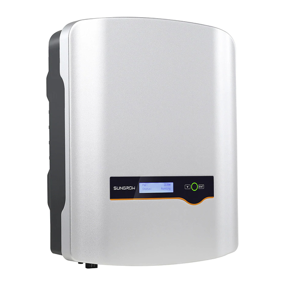
User Manual 2 Product Introduction Item Description Remarks Sungrow single-phase Measures the export power and communicates or three-phase meter with the inverter via an RS485 connection. (optional) Utility grid Grid earthing system types: TT, TN. Household load Devices that consume energy. - Page 14 2 Product Introduction User Manual Fig. 2-2 Inverter Appearance (SG5K-D for reference) Item Name Description Positive and negative DC input connectors. PV terminals One or two or three pairs, depending on inverter type. DC switch To disconnect the DC current safely. RS485 Can be connected to Wi-Fi communication module.
- Page 15 Fig. 2-3 Dimensions of the Inverter Tab. 2-2 Dimensions and Weight Type W (mm) H (mm) D (mm) Weight (kg) SG2K-S / SG3K-S SG3K-D / SG4K-D / 11.5 SG5K-D / SG6K-D SG8K3-D 15.5 LCD Panel The LCD panel with a screen, an indicator and two buttons is on the front of the inverter.
-
Page 16: Energy Meter (Optional)
Tab. 6-2. 2.3 Energy Meter (Optional) The Sungrow Energy Meter is installed next to the main switch to detect the electrical measured values at the grid-connected point. It communicates with the inverter via an RS485 connection. The dimensions are shown below. -
Page 17: Function Description
Wi-Fi module for details. It is recommended to use the communication module from Sungrow. Using a device from other companies may lead to communication failure or other unexpected damage. Further information on the communication module can be found in the respective Quick Installation Guide. -
Page 18: Reactive Power Regulation
Setting”. Q(p) Mode The Q(p) mode is not applicable to SG2K-S. This mode is disabled by default. You can enable this function via the cloud server www.isolarcloud.com.hk. Then, after any change in active power, the inverter is able to adjust the reactive power automatically according to the following power factor curve. -
Page 19: Regular Operational Voltage Range
User Manual 2 Product Introduction The power factor curve can only be disabled when the voltage goes back to a value below the shutdown voltage level, adjustable value between 90 % and 100 % of nominal voltage level, with default voltage level at 100 % adjusted at factory. -
Page 20: Regular Operational Frequency Range
2 Product Introduction User Manual Tab. 2-4 Disconnection related to Voltage Voltage Level at Grid-connected Point (% related to Local Nominal Maximum Time to Disconnect Voltage) V < 95 % 0.16 s 95 % <= V <= 105 % Normal operation V >... - Page 21 User Manual 2 Product Introduction than 62 Hz, the inverter will reduce the active power export to grid according to the following equation: △ P = [f x (f +0.5)] x R grid nominal Where: △ − P is the variation of active power export to grid (in %) related to the active power export to gird at the moment frequency surpass 60.5 Hz.
- Page 22 2 Product Introduction User Manual Tab. 2-6 Disconnection related to Frequency Grid Frequency Level Maximum Time to Disconnect f < 59.3 Hz 0.16 s 59.3 Hz <= f <= 60.5 Hz Normal operation f > 60.5 Hz 0.16 s When the frequency level is out of the operational levels shown in the table, the inverter will disconnect from the grid.
-
Page 23: Unpacking And Storage
Check the delivery contents for completeness according to the packaging list. Contact SUNGROW or the distributor in case of any damaged or missing components. It is the best choice to store the inverter in the original packaging. So, do not dispose of it. -
Page 24: Identifying The Inverter
Fig. 3-2 Nameplate of Inverter * The image shown here is for reference only. The actual product you receive may differ. Item Description Item Description SUNGROW logo and product Marks certification type institutions Barcode, company name and Technical data origin Tab. -
Page 25: Delivery Contents
User Manual 3 Unpacking and Storage Icon Description TÜV mark of conformity. CE mark of conformity. INMETRO mark. 3.3 Delivery Contents Standard Delivery Wall-mounting bracket Documents Inverter Wi-Fi module M4x80 screw set Communication connector M4x10 grounding screw AC connector set PV connector set Fig. -
Page 26: Storage Of Inverter
3 Unpacking and Storage User Manual Optional Accessory Single-phase meter and Three-phase meter and cables cables The single-phase Energy Meter and the three-phase Energy Meter are optional. The meter figures in this document have been created for the single-phase Energy Meter unless otherwise specified. 3.4 Storage of Inverter If you do not install the inverter immediately, choose an appropriate location to store it. -
Page 27: Mechanical Mounting
4 Mechanical Mounting 4.1 Safety during Mounting Make sure there is no electrical connection before installation. In order to avoid electric shock or other injury, be sure there is no electricity or plumbing installations before drilling holes. Risk of injury due to improper handling ... - Page 28 4 Mechanical Mounting User Manual Do not install the inverter in the living area or bedrooms. The noise during its operation may affect daily life. The location should be not accessible to children. The ambient temperature and relative humidity should meet the following requirements.
-
Page 29: Tools
User Manual 4 Mechanical Mounting Forward tilt Backward tilt Upside down Horizontally Clearance requirement and multiple installation: 400 mm 400 mm For multi-row installation, the distance between two adjacent rows should be at least 400 mm. 4.3 Tools General tools (recommended) Packaging tape Marker Measuring tape... - Page 30 4 Mechanical Mounting User Manual Dust mask Earplugs Goggles Insulated shoes Vacuum cleaner Heat shrink tubing Installation tools (recommended) Heat gun Hammer drill Rubber mallet Drill bit: φ10 Electric screwdriver Phillips screwdriver Wire stripper Hydraulic plier Wire crimper Wrench for MC4 terminal Crimping range: 2.5-6mm²...
-
Page 31: Installing The Inverter
User Manual 4 Mechanical Mounting Torx screwdriver Socket wrench TX30 Open end: 10mm (for M6 bolts) 13mm (for M8 bolts) 16mm (for M10 bolts) 4.4 Installing the Inverter Inverter is installed on the wall by means of wall-mounting bracket and the expansion plug sets. - Page 32 4 Mechanical Mounting User Manual Wall-mounting bracket Fender washer Spring washer Self-tapping screw Expansion tube Mount the inverter to the bracket, and secure it with an M4x80 screw (torque: 1.5 Nm). To protect the inverter from theft, you can lock it with a padlock.
-
Page 33: Installing The Energy Meter
User Manual 4 Mechanical Mounting 4.5 Installing the Energy Meter The SUNGROW Energy Meter should be installed between the grid and the load. It supports a 35 mm DIN-rail installation, as shown in the following figure. Single-phase Energy Meter Three-phase Energy Meter... -
Page 34: Electrical Connection
5 Electrical Connection Prior to any electrical connections, keep in mind that the inverter has dual power supplies. It is mandatory for the technical personnel to wear personal protective equipments (PPE) during the electrical work. Danger to life due to a high voltage inside the inverter ... -
Page 35: Terminal Description
User Manual 5 Electrical Connection Fig. 5-1 Electrical Connection Diagram Item Name Remarks -S series: one pair of PV terminals. PV strings -D series: three pairs for SG8K3-D and two pairs for other –D inverters. Wi-Fi module RS485 communication. Used as a protective device during electrical connection. -
Page 36: Grounding The Inverter
5 Electrical Connection User Manual * Image shown here is for reference only. The actual product you receive may differ. Tab. 5-1 Terminal Descriptions Item Terminal Description MC4 terminals for PV inputs. -S series: one pair of PV terminals. PV terminals -D series: three pairs for SG8K3-D and two pairs for the other –D inverter types. -
Page 37: Grid Connection
An independent two-pole AC circuit breaker for the inverter must be installed at the output side for safe disconnection. The recommended specifications are as follows: Inverter Type Specification SG2K-S / SG3K-S / SG3K-D 25 A SG4K-D / SG5K-D / SG6K-D 32 A SG8K3-D... -
Page 38: Assembling The Ac Connector
5 Electrical Connection User Manual Cross-section (mm²) Cable diameter (mm) Type Range Recommended Range Recommended SG2K-S / SG3K-S / 4…6 10…14 SG3K-D SG4K-D / SG5K-D / 4…6 10…14 SG6K-D SG8K3-D 5.3.2 Assembling the AC Connector Lead the AC cable through the Remove the cable jacket by cable gland and the housing. -
Page 39: Installing The Ac Connector
User Manual 5 Electrical Connection 5.3.3 Installing the AC Connector Disconnect the AC circuit breaker and secure it against reconnection. Measure the voltage and frequency of the grid-connected point to ensure that they are within the specified range listed in “10.1 Technical Data”. Align the AC connector and the AC terminal and mate them together by hand. -
Page 40: Pv Connection
PV input Inverter inside Total PV Input Open-circuit Short-circuit Type Power Limit Voltage Limit Current Limit SG2K-S 3000 W 600 V 12 A SG3K-S 4000 W 600 V 12 A -D Series For –D inverters except SG8K3-D, there are two pairs of PV terminals, each with its MPP tracker. - Page 41 User Manual 5 Electrical Connection The PV1 and PV2 can be configured in independent mode or parallel mode. For SG8K3-D, the PV strings to PV2 input should have the same PV module type, the same string length, identical tilt and identical orientation.
- Page 42 5 Electrical Connection User Manual Total PV Input Open-circuit Short-circuit Type Power Limit Voltage Limit Current Limit SG6K-D 7800 W 600 V / 600 V 12 A / 12 A SG8K3-D 10800 W 600 V / 600 V / 600 V 15 A / 15 A / 15 A Only the current is limited for a single input and the power is not limited.
-
Page 43: Assembling The Pv Connector
User Manual 5 Electrical Connection Total Input Open-circuit Short-circuit Type Power Limit Voltage Limit Current Limit SG3K-D 4000 W 600 V 24 A SG4K-D 5200 W 600 V 24 A SG5K-D 6500 W 600 V 24 A SG6K-D 7800 W 600 V 24 A SG8K3-D... -
Page 44: Installing The Pv Connector
5 Electrical Connection User Manual 3. Lead the cable through cable gland, and insert into the insulator until it snaps into place. Then tighten the cable gland (torque 2.5 Nm to 3 Nm). Positive Insulator Negative Insulator Crimp Contact Crimp Contact Cable Gland Cable Gland Make sure that the cable polarity of each PV string is correct before... -
Page 45: Rs485 Communication Connection
Inverter”. More detailed information for the Wi-Fi module can be found in the respective manual. The RS485 terminal can also be used to connect an external RS485 device. For the pin definition and waterproof procedure, please contact SUNGROW. Failure to comply with the requirements of wiring or waterproofing will void the warranty. -
Page 46: Optional) Meter Communication Connection
5 Electrical Connection User Manual 5.6 (Optional) Meter Communication Connection The SUNGROW single-phase energy meter should be installed next to the main switch. Solar switch Main Meter switch link Network Utility Sungrow meter meter grid PV strings Inverter Home Appliance 5.6.1 On the Meter Side... - Page 47 User Manual 5 Electrical Connection Connect the cables to the meter. − (a) Tighten the power supply wires to Grid terminal 3 (L) and terminal 6 (N). − (b) Tighten the RS485 wires to Load terminal 2 and terminal 5. −...
-
Page 48: On The Inverter Side
5 Electrical Connection User Manual Connect the A and B plugs to terminals A and B on the Energy Meter, as shown below. Strip the insulation from the power wires by 10 mm. Then connect the wires to the terminals on the Energy Meter, as shown below. (Cross-section: 10 mm to 25 mm Load side... - Page 49 User Manual 5 Electrical Connection Loosen the screws and remove the waterproof lid from RS485|DRM terminal. Note: Retain the screws for later installation. Insert the RJ45 plug into the left (Meter) port until it makes a “click” sound. Secure the waterproof lid to the inverter bottom with four screws, then fasten the cable gland.
-
Page 50: Commissioning
Commissioning Proper commissioning is essential for the system, to protect it against fires, injury and electric shock. 6.1 Inspection before Commissioning Check the following items before starting the inverter: All the installation sites are convenient for operation, maintenance and service. Check and confirm that the inverter is firmly installed. -
Page 51: Commissioning Procedure
User Manual 6 Commissioning 6.3 Commissioning Procedure Make sure all the above mentioned items meet the requirements. Connect the external AC circuit breaker. Rotate the DC switch to “ON”. If there is sufficient sunlight, the inverter will enter the running state and start to feed AC power to the grid. -
Page 52: Lcd Operation
7 LCD Operation 7.1 Button Function The inverter offers two buttons with multiple functions. Please refer to the following table before any operation of the inverter. Tab. 7-1 Button function Button Operation Description Navigate up / down or change the setting values. ≤1.2 s Hereinafter referred to as “Touch ESC”. - Page 53 Whether the insolation is sufficient and the PV connection is correct. If no anomaly is found, disconnect and reconnect the DC switch and the main switch to restart. If it still does not work, contact SUNGROW.
-
Page 54: Menu Structure
7 LCD Operation User Manual Viewing the Active Error/Warning If the status on the main screen is “Error xxx”, Error Touch ENT to view the active error code. If the inverter is running with a warning, Touch ENT to view the active warning code. Only one error or warning can be displayed on Warning this screen. -
Page 55: Viewing Running Info
User Manual 7 LCD Operation 7.4 Viewing Running Info Proceed as follows to look through the detailed running information. Main Screen (Press ENT)→Menu→Run Info (Press ENT) Scroll pages by touching ENT / ESC. E-today: 20.0kWh Vpv1: 250.0V Vpv2: 244.4V E-total: 1999kWh Ipv2: 2.6A... -
Page 56: Setting Protective Parameters
7 LCD Operation User Manual 7.5.2 Setting Protective Parameters Protective parameters are designed for the threshold values that can trigger the protective function of the inverter. The threshold values are compliant with the requirements of local safety standards and the utility grid. If the protection function is triggered, the inverter will automatically disconnect from the grid with the ”Error xxx”... - Page 57 228.0 min-rec Grid Protection Voltage Adjusting All Sungrow’s inverters are compliant with the local standard related to grid protection requirements. In order to work with unstable utility grids, inverters are equipped with automatic protection voltage adjusting function (disabled by default). This mode can be enabled via the LCD.
-
Page 58: Zero-Export Setting
High line voltages may damage home appliances and Sungrow is not held responsible or liable for these issues. 7.5.3 Zero-export Setting Touch ENT / ESC to select and press ENT to confirm. -
Page 59: Adding The Existing Inverter
7 LCD Operation With the password 111, the zero-export setting can only be done at the first time. The later modification can be performed by professionals only, please contact SUNGROW. 7.5.4 Adding the Existing Inverter Rated-P: rated power of the existing inverter. -
Page 60: Setting Communication Parameter
7 LCD Operation User Manual Touch ESC to add the value and Touch ENT to move the cursor. Press ENT to confirm the setting. The “+” can be changed to “-” by touching ESC. +0000 kWh The adjustment rangs from -9999 kWh to +9999 kWh. -
Page 61: Viewing The Error Record
User Manual 7 LCD Operation 7.7 Viewing the Error Record Main Screen (Press ENT)→Menu (Touch ESC)→Error Record (Press ENT) Scroll pages by touching ENT / ESC. 1 15/01/21 09:10:12 3 records can be displayed on each page and 2 15/01/21 09:10:08 3 15/01/21 09:11:08 20 records at most for all. -
Page 62: Viewing Device Info
7 LCD Operation User Manual Tab. 7-6 Country Code Description Code Full Name Language Code Full Name Language Great Britain English Brazil Portuguese Germany German China Chinese France French Sweden English Italy Italian Thailand English Spain English Korea English Austria German Luxemburg German... -
Page 63: Troubleshooting And Maintenance
4. Check whether the voltage of DC input exceeds the inverter start-up voltage. 5. If all the above conditions are OK, please contact SUNGROW. 8.1.2 Errors on the App or LCD Screen If an error occurs, the “Error” state will be shown on the main screen. We need the following information to provide you with the best assistance: ... - Page 64 3. If the grid voltage is within the permissible range, contact Sungrow Service Dept. 1. This is a short-term fault due to grid Transient over-voltage. condition. Wait a moment for inverter grid transient recovery.
- Page 65 Grid failure (Islanding) 3. Check whether grid is not in service. 4. If all conditions are OK and this fault still occurs in the LCD screen, contact Sungrow Service Dept. injection over-current. 1. Wait a moment for inverter recovery.
- Page 66 1. Wait a moment for inverter recovery. Relay fault on the grid 2. If the fault occurs repeatedly, contact side. Sungrow Service Dept. 1. Check whether there is a reliable inverter grounding line. insulation 2. Check whether one of the PV strings is resistance of PV to short-circuited with ground.
- Page 67 2. If the fault occurs repeatedly, contact protective range. Sungrow Service Dept. Communication alarm 1. Wait 1 minute for inverter recovery. between master DSP 2. If the fault persists, contact Sungrow and slave DSP. Service Dept. Alarm for no inverter Contact Sungrow Service Dept. type setting.
- Page 68 8 Troubleshooting and Maintenance User Manual Code Description Troubleshooting Grid under-frequency. permissible range, contact Sungrow Service The grid frequency is Dept. below the protective value, which is lower than protective value of error 009. Abnormal grounding. Neither the PE terminal...
-
Page 69: Routine Maintenance
1. Inverter can normally be connected to the External memory grid. reading/writing 2. Power on the inverter again. If the fault warning. persists, contact Sungrow Service Dept. Abnormal communication Check whether power cable warning connections of the meter are correct. - Page 70 Unauthorized alterations will void guarantee and warranty claims and in most cases terminate the operating license. SUNGROW shall not be held liable for any damage caused by such changes. Any malfunction that may impair the inverter safety operation must be repaired immediately before the inverter is restarted.
-
Page 71: System Decommissioning
9 System Decommissioning 9.1 Disconnecting the Inverter For maintenance or other service work, the inverter must be switched off. Proceed as follows to disconnect the inverter from the AC and DC power sources. Lethal voltages or damage to the inverter will follow if otherwise. Stop the inverter via the LCD menu. -
Page 72: Dismantling The Inverter
9 System Decommissioning User Manual 9.2 Dismantling the Inverter Risk of burn injuries and electric shock! Do not touch any inner live parts until at least 10 minutes after disconnecting the inverter from the utility grid and the PV input. Refer to “5 Electrical Connection”... -
Page 73: Appendix
10 Appendix 10.1 Technical Data 10.1.1 –S Series Parameters SG2K-S SG3K-S Input Data Max. PV input power 3000 W 4000 W Max. PV input voltage 600 V Startup voltage 120 V Nominal input voltage 360 V MPP voltage range 90 V–560 V MPP voltage range for nominal 210 V–480 V... -
Page 74: D Series
10 Appendix User Manual Parameters SG2K-S SG3K-S PV reverse connection protection AC short circuit protection Leakage current protection Anti-islanding protection Yes (frequency shift) DC switch Overvoltage category III [AC], II [DC] Overvoltage protection II [AC] Safety protection class System Data Max. - Page 75 User Manual 10 Appendix Parameters SG3K-D SG4K-D power No. of MPPTs Max. number of PV strings per MPPT Max. PV input current 20 A (10 A / 10 A) Max. current for input connector 24 A (12 A / 12 A) Short-circuit current of PV input 24 A (12 A / 12 A) Max.
- Page 76 10 Appendix User Manual Parameters SG3K-D SG4K-D Operating ambient temperature -25℃ to +60℃ Allowable relative humidity 0–100 % (non-condensing) Cooling method Natural cooling Max. operating Altitude 4000 m (derating when > 2000 m) Display Graphic LCD Communication Wi-Fi PV connection type AC connection type Plug and play connector IEC 62109-1, IEC 62109-2, IEC 62116,...
- Page 77 User Manual 10 Appendix Parameters SG5K-D SG6K-D Nominal AC voltage 220 Vac / 230 Vac / 240 Vac 176 Vac–276 Vac AC voltage range (this may vary with grid standards) Nominal grid frequency 60 Hz 55 Hz–65 Hz Grid frequency range (this may vary with grid standards) Total harmonic distortion (THD) <...
- Page 78 10 Appendix User Manual Parameters SG8K3-D Input Data Max. PV input power 10800 W Max. PV input voltage 600 V Startup voltage 120 V Nominal input voltage 360 V MPP voltage range 90 V–540 V MPP voltage range for nominal 285 V–480 V power No.
-
Page 79: Quality Assurance
Evidence During the warranty period, the customer shall provide the product purchase invoice and date. In addition, the trademark on the product shall be undamaged and legible. Otherwise, SUNGROW has the right to refuse to honor the quality guarantee. - Page 80 The customer shall give SUNGROW a reasonable period to repair the faulty device. Exclusion of Liability In the following circumstances, SUNGROW has the right to refuse to honor the quality guarantee: If the free warranty period for the whole machine/components have expired.
- Page 81 Type of the inverter Serial number of the inverter Error code/name Brief description of the problem China (HQ) Australia Sungrow Power Supply Co., Ltd Sungrow Australia Group Pty. Ltd. Hefei Sydney +86 551 65327834 +61 2 9922 1522 service@sungrowpower.com service@sungrowpower.com.au...
- Page 82 Sungrow Power Korea Limited Tokyo Seoul +81 3 6262 9917 +82 70 7719 1889 japanservice@jp.sungrowpower.com service@kr.sungrowpower.com Malaysia Philippines Sungrow SEA Sungrow Power Supply Co., Ltd Selangor Darul Ehsan Mandaluyong City +60 19 897 3360 +63 9173022769 service@my.sungrowpower.com service@ph.sungrowpower.com Thailand Spain Sungrow Ibérica S.L.U.
- Page 83 User Manual 10 Appendix Vietnam Sungrow Vietnam Hanoi +84 918 402 140 service@vn.sungrowpower.com...
Need help?
Do you have a question about the SG2K-S and is the answer not in the manual?
Questions and answers