Table of Contents
Advertisement
Quick Links
Advertisement
Chapters
Table of Contents
Troubleshooting

Subscribe to Our Youtube Channel
Related Manuals for NetCommWireless NF18ACV


Summary of Contents for NetCommWireless NF18ACV
-
Page 1: User Guide
NF18ACV VDSL/ADSL2+ Dual Band AC1600 Gigabit Gateway with VoIP User Guide... -
Page 2: Important Notice
NetComm Wireless accepts no responsibility for any loss or damage resulting from errors or delays in transmission or reception, or the failure of the NetComm Wireless NF18ACV to transmit or receive such data. -
Page 3: Document History
Document history This guide covers the following products: VDSL/ADSL2+ Dual Band AC1600 Gigabit Gateway with VoIP (NF18ACV) Ver. Document description Date v1.0 Initial document release August 2017 Table i. – Document revision history VDSL/ADSL2+ Dual Band AC1600 Gigabit Gateway with VoIP 3 of 131 ©... -
Page 4: Table Of Contents
Rear ..............................................15 Left Side ............................................16 Safety and product care ..................................17 Transport and handling ..................................17 Installation and configuration of the NF18ACV ..........................18 Placement of your NF18ACV ......................................18 Avoiding obstacles and interference....................................18 Cordless phones ..........................................18 Choosing the “quietest”... - Page 5 WAN ............................................... 28 Statistics............................................30 Statistics – LAN ........................................30 Statistics – WAN Service ......................................30 Statistics – xTM ........................................31 Statistics – xDSL ........................................32 Route .............................................. 33 ARP ..............................................33 DHCP ............................................... 33 CPU & Memory ..........................................34 Advanced Setup....................................
- Page 6 IPv6inIPv4 ..........................................71 IPv4inIPv6 ..........................................72 IPSec ............................................... 74 Wireless ......................................77 WiFi 2.4GHz/WiFi 5GHz ........................................77 Wireless – Basic ........................................77 Wireless – Security ........................................79 Wireless – MAC Filter ....................................... 80 Wireless – Wireless Bridge (Wireless Distribution Service) ............................81 Wireless –...
- Page 7 Management – Access Control ..................................... 106 Passwords ..........................................107 Access List ..........................................107 Services Control ........................................108 Management – Update Firmware ....................................108 Management – Reboot ......................................... 109 Additional Product Information ............................... 110 Establishing a wireless connection....................................110 Windows 7 ..........................................110 Windows 8/8.1/10 .........................................
-
Page 8: Overview
The individual reading this manual is presumed to have a basic understanding of telecommunications terminology and concepts. Prerequisites Before continuing with the installation of your NF18ACV, please confirm that you meet the minimum system requirements below. An activated ADSL/VDSL or pre-configured WAN connection. -
Page 9: Welcome
Welcome Thank you for purchasing a NetComm Wireless NF18ACV. This guide contains all the information you need to configure your device. Product overview Fully featured VDSL2 / ADSL2+ gateway 4 x Gigabit Ethernet 10/100/1000 LAN ports nbn and UFB ready – ultra-fast connection to nbn and UFB fibre network - 1 x 10/100/1000 Gigabit Ethernet WAN port VoIP feature for HD quality voice calls - connect up to 2 telephones Next generation WiFi 802.11 AC1600, dual band concurrent, for multiple high-speed wireless connections... -
Page 10: Product Features
UFB ready Featuring VDSL2/ADSL2 technologies as well as a Gigabit WAN port, the NF18ACV is a 3-in-1 gateway that provides access to ADSL networks, VDSL and all nbn and UFB fibre network options: FTTN, FTTB, FTTH. -
Page 11: Media Sharing
The NF18ACV is equipped with 5GHz 3 x 3 MIMO and 2.4GHz 2 x 2 MIMO internal antennas to provide optimum reception while offering a powerful signal throughout the home. Create an ultra-fast 1600 Mbps WiFi home network and connect a multitude of wireless devices such as smart TVs, set top boxes, laptops, tablets, computers, NAS, smart phones and gaming consoles with upgraded coverage and performance. -
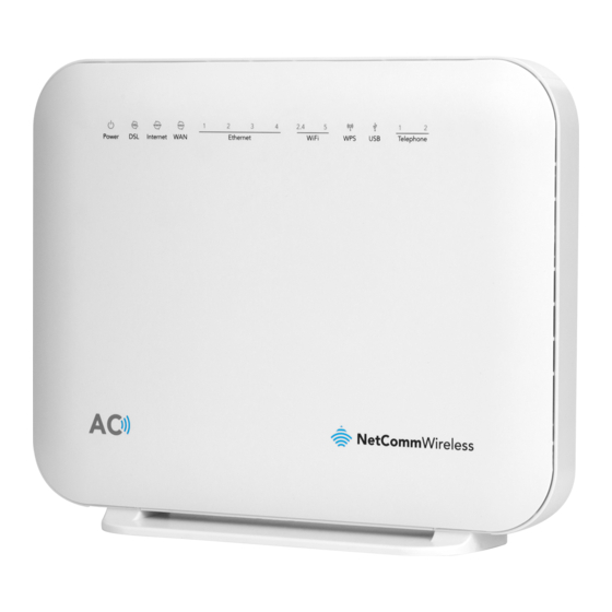
Page 12: Physical Dimensions And Indicators
LED indicators The NF18ACV has been designed to be placed on a desktop. All of the cables exit from the rear for easy organization. The display is visible on the front of the NF18ACV to provide you with information about network activity and the device status. -
Page 13: Physical Dimensions And Weight
Green Blinking Incoming call or the handset is in use. No handset registered Table 1 – LED indicator table Physical dimensions and weight The table below lists the physical dimensions and weight of the NF18ACV. Dimensions Width 216 mm Height... -
Page 14: Table 5 - Nf18Acv Web Interface Access Table
NF18ACV WEB Interface Access Username admin Password admin Table 5 – NF18ACV WEB Interface Access table 14 of 131 User Guide © NetComm Wireless 2017... -
Page 15: Interfaces
Interfaces Rear The following interfaces are available on the NF18ACV: Figure 1 – NF18ACV router rear view Interface Description Use the provided RJ11 cable to connect the router to the telephone line operating your xDSL service. Telephone 1 and 2 Connect a regular analogue telephone handset here for use with a VoIP service. -
Page 16: Left Side
Connection point for the included power adapter. Connect the power supply here. Table 6 – Rear interface table Left Side Figure 2 – NF18ACV router side view Interface Description 2.4G WPS button Press the 2.4G WPS button to activate the WPS PBC pairing function for the 2.4GHz radio. -
Page 17: Safety And Product Care
Do not place the device in direct sunlight or in hot areas. Transport and handling When transporting the NF18ACV, it is recommended to return the product in the original packaging. This ensures that the product will not be damaged. Attention – In the event the product needs to be returned, ensure it is securely packaged with appropriate padding to prevent damage during courier transport. -
Page 18: Installation And Configuration Of The Nf18Acv
The wireless connection between your NF18ACV and your WiFi devices will be strong when they are in close proximity and have direct line of sight. As your client device moves further away from the NF18ACV or solid objects block direct line of sight to the router, your wireless connection and performance may degrade. -
Page 19: Choosing The "Quietest" Channel For Your Wireless Network
If your phone supports channel selection, change the channel on the phone to the farthest channel from your wireless network. For example, change the phone to channel 1 and move your NF18ACV to channel 11. See your phone’s user manual for detailed instructions. -
Page 20: Hardware Installation
Wait approximately 60 seconds for the NF18ACV to power up. Connecting a client via Ethernet cable Connect the yellow Ethernet cable provided to one of the yellow ports marked ‘Ethernet’ at the back of the NF18ACV. Connect the other end of the yellow Ethernet cable to your computer. -
Page 21: Web Based Configuration Interface
It is also possible to initially set up your router using the Basic Setup wizard and then later fine-tune your configuration using the Advanced Setup tools. Please follow the steps below to configure your NF18ACV Wireless router via the web based configuration wizard. Open a web browser and type http://192.168.20.1/... -
Page 22: Figure 4 - Nf18Acv Router - Select Adsl As Wan Connection Type
Figure 4 – NF18ACV router – Select ADSL as WAN connection type Select either the PPPoE, PPPoA or Bridging for your internet connection as specified by your Internet Service Provider (ISP). Figure 5 – Select PPPoE as WAN mode Click the Next button. -
Page 23: Vdsl
VDSL Select VDSL and click the Next button. Figure 7 – NF18ACV router – Select VDSL as WAN connection type Select the WAN mode for your internet connection as specified by your Internet Service Provider (ISP). Figure 8 – Select WAN mode for VDSL connection Click the Next button. -
Page 24: Ethernet Wan
Click the Finish button when you have entered the required details. The account settings are saved and the NF18ACV connects to the internet. Ethernet WAN Connect an RJ45 Ethernet cable to the WAN port on the NF18ACV. Connect the other end of the cable to your WAN service. Select Ethernet WAN then click the Next button. -
Page 25: Ppp Over Ethernet (Pppoe)
PPP over Ethernet (PPPoE) If at step 3 you selected PPP over Ethernet (PPPoE): Select the correct VLAN option for your connection. For New Zealand customers, the requirement for VDSL is VLAN tag 10. If you are not sure of the tagging requirement for your connection, please contact your ISP. Figure 13 –... -
Page 26: Figure 15 - Ip Over Ethernet (Ipoe) -- Vlan Setup
Click the Next button. The settings are displayed in a summary. Figure 17 – WAN Setup Summary Click Apply/Save to save them. The account settings are saved and the NF18ACV connects to the internet. 26 of 131 User Guide © NetComm Wireless 2017... -
Page 27: Device Info
When you log in to the router, the Device Info summary page is displayed, giving a general overview of the status of the router and the WAN connection. Figure 18 – NF18ACV route – Device Info summary page Item Definition... -
Page 28: Wan
Table 8 – Device Info summary table The WAN page shows more detailed information related to the WAN interface configuration, including the firewall status, IPv4 and IPv6 addresses of the router. Figure 19 – NF18ACV router – WAN Info list Item Definition Interface The Interface of the WAN connection. -
Page 29: Table 9 - Wan Info Table
Item Definition VLAN Mux ID Details the status of VLAN Mux ID if used. IPv6 The status of IPv6. IGMP Pxy Details the status of IGMP on each WAN connection. IGMP is only used with IP v4 connections. IGMP proxy enables the router to issue IGMP host messages on behalf of hosts that the router discovered through standard IGMP interfaces, allowing NAT transversal of Multicast traffic. -
Page 30: Statistics
Statistics Statistics – LAN The Statistics – LAN page shows detailed information about the number of bytes, packets, errors and dropped packets on each LAN interface in both directions of communication. Figure 20 – Device Info – Statistics -- LAN display Interface Description Received/Transmitted... -
Page 31: Statistics - Xtm
Interface Description Received/Transmitted Bytes Rx/Tx (receive/transmit) packets in bytes. Packets Rx/Tx (receive/transmit) packets. Errors Rx/Tx (receive/transmit) packets with errors. Drops Rx/Tx (receive/transmit) packets with drops. Table 11 – Statistics – WAN Service table Statistics – xTM The Statistics – xTM page shows details related to the xTM (ATM/PTM) interface of the router. Figure 22 –... -
Page 32: Statistics - Xdsl
Statistics – xDSL The Statistics – xDSL page shows details related to the DSL interface of the router. Figure 23 – NF18ACV router 32 of 131 User Guide © NetComm Wireless 2017... -
Page 33: Route
Route The Route page displays any routes that the router has created. Figure 24 – Device Info -- Route list Click ARP to display the address resolution protocol information. This option can be used to determine which IP address / MAC address is assigned to a particular host. This can be useful when setting up URL filtering, Time of Day filtering or Static DHCP addressing. -
Page 34: Cpu & Memory
CPU & Memory The CPU & Memory page shows real-time graphs charting the physical memory usage and the work load of the CPU. Figure 27 – Device Info – CPU & Memory display 34 of 131 User Guide © NetComm Wireless 2017... -
Page 35: Advanced Setup
Advanced Setup While you can set up your router directly from the Advanced Setup pages, we recommend that you use the First-time Setup Wizard contained in the Basic Setup section, see above. Layer2 Interface ATM Interface The ATM (Asynchronous Transfer Mode) interface page shows the settings of all available DSL ATM interfaces. ATM interface is used for ADSL connections. -
Page 36: Ptm Interface
Field Description IP QoS This field shows the status of the Quality of Service (QoS) function. MPAAL Prec/Alg/Wght This displays data related to QoS Queue priority and algorithm. Check the box in this field and click Remove to permanently delete the Remove ATM configuration. -
Page 37: Eth Interface
Click the Add button to create a new PTM interface. Enter the details as required by your Internet Service Provider and click the Apply/Save button. Figure 31 – PTM Configuration page ETH Interface The ETH interface page allows you to add or remove ETH WAN interfaces. Figure 32 –... -
Page 38: Wan Service
Internet access. Attention – WAN service requires a preconfigured Layer 2 interface, be it ATM/PTM or Ethernet WAN. Figure 33 – NF18ACV router To add a WAN service, click the Add button. Use the drop down list to select the layer 2 interface to use for the WAN service and click the Next button. -
Page 39: Ppp Over Ethernet
Figure 35 – WAN Service – Select WAN Service Type PPP over Ethernet Enter the PPPoE authentication details as required by your Internet Service Provider and click the Next button. Figure 36 – Enter PPP over Ethernet details VDSL/ADSL2+ Dual Band AC1600 Gigabit Gateway with VoIP 39 of 131 ©... -
Page 40: Ip Over Ethernet
IP over Ethernet Enter the details as required by your Internet Service Provider and click the Next button. Figure 37 – Enter IP over Ethernet details Select the NAT Translation settings as desired and click the Next button. Figure 38 – Enter PPP over Ethernet NAT Translation settings 40 of 131 User Guide ©... -
Page 41: Bridging
Bridging When you select Bridging mode, a summary of the settings is displayed. Click Apply/Save to commit the settings. Figure 39 – Enter PPP over Ethernet details IPv4 Autoconfig The LAN window allows you to modify the settings for your local area network (LAN). Figure 40 –... -
Page 42: Figure 41 - Enter Dhcp Static Ip Addresses
To set a DHCP reservation, enter the MAC Address of the chosen host and IP to use and then click Apply/Save. The NF18ACV enables you to set the DHCP options which are provided to hosts attempting to connect to the DHCP server. -
Page 43: Ipv6 Autoconfig
IPv6 Autoconfig The IPv6 LAN Auto Configuration page allows you to configure settings pertaining to the IPv6 service. Figure 42 – IPv6 LAN Auto Configuration page Option Definition Enable Unique Local Enable the use of unique local addresses. The router will advertise the IPv6 /64 Addresses and Prefix prefix to new devices on the network. -
Page 44: Table 15 - Ipv6 Lan Auto Configuration Settings
Option Definition Enable DHCPv6 The Router Advertisement Daemon (radvd) is an open-source software product Server or RADVD that implements link-local advertisements of IPv6 router addresses and IPv6 routing prefixes using the Neighbour Discovery Protocol (NDP) as specified in RFC 2461. The Router Advertisement Daemon is used by system administrators in stateless auto-configuration methods of network hosts on Internet Protocol version 6 networks. -
Page 45: Lan Vlan Setting
LAN VLAN Setting This page allows you to specify a LAN port to apply VLAN tagging to. Figure 43 – Specify a LAN port for VLAN tagging Select the LAN port using the drop down menu, then click the Add button. Enter the VLAN ID and in the Pbits field, enter a value from 0-7 indicating the priority bits that dictates the priority of the VLAN. -
Page 46: Figure 45 - Nat -- Virtual Server Configuration Page
Figure 45 – NAT -- Virtual Server Configuration page Field Description Select a Service or custom Select a pre-configured port forwarding rule or choose custom server to Server create your own port forwarding rule. Server IP Address Enter the IP address of the local server/host. External Port Start Enter the starting external port number range (when custom server is selected). -
Page 47: Port Triggering
Port Triggering Some applications require specific ports in the Router’s firewall to be open for access by remote parties. Port Triggering opens up the ‘Open Ports’ in the firewall when an application on the LAN initiates a TCP/UDP connection to a remote party using the ‘Triggering Ports’. -
Page 48: Dmz Host
DMZ Host The NF18ACV will forward IP packets from the Wide Area Network (WAN) that do not belong to any of the applications configured in the Virtual Servers table or being used in the Virtual Server table to the DMZ host. -
Page 49: Alg
The Application Layer Gateway (ALG) is a feature which enables the router to parse application layer packets and support address and port translation for certain protocols. We recommend that you leave these protocols enabled unless you have a specific reason for disabling them. Figure 49 –... -
Page 50: Figure 51 -Outgoing Ip Filter Settings
Outgoing IP Filtering By default, the router allows all outgoing Internet traffic from the LAN but by setting up Outgoing IP Filtering rules, you can block some users and/or applications from accessing the Internet. To delete the rule, click in the Remove column next to the selected rule and then click the Remove button. To create a new outgoing IP filter, click Add. -
Page 51: Figure 52 - Incoming Ip Filter Settings
Incoming IP Filtering By default, when NAT is enabled, all incoming IP traffic from WAN is blocked except for responses to requests from the LAN. However, some specific incoming traffic from the Internet can be accepted by setting up Incoming IP Filtering rules. To delete the rule, click ... -
Page 52: Mac Filtering
MAC Filtering The NF18ACV offers the ability to use MAC Address filtering on ATM PVCs. You can elect to block or allow connections based on MAC Address criteria. The default policy is to allow all connections. Figure 53 – Security – MAC Filter list Click Add to enter a new MAC Address filter. -
Page 53: Parental Control
Parental Control The Parental Control feature allows you to take advanced measures to ensure the computers connected to the LAN are used only when and how you decide. Time Restriction This Parental Control function allows you to restrict access from a Local Area Network (LAN) connected device to an outside network through the router on selected days and at certain times. -
Page 54: Url Filter
Internet via the NF18ACV. Select the Black List (to block) or White List (to allow) option and then click Add to enter the URL you wish to add to the URL Filter list. -
Page 55: Quality Of Service
Field Description Start Time The time of day when the restriction starts. (24 hour time: 00:00–23:59) End time The time of day when the restriction ends. (24 hour time: 00:00–23:59) Apply/Save button Press the Apply/Save button to save a time restriction rule. Table 21 –... -
Page 56: Qos Queue
QoS Queue Figure 60 – Advanced – QoS Queue Setup Click the Add button to add a QoS Queue. The following screen is displayed. Figure 61 – Advanced – QoS – Add QoS Queue The above screen allows you to configure a QoS queue entry and assign it to a specific network interface. Each of the queues can be configured for a specific precedence. -
Page 57: Qos Classification
WLAN Queue The QoS WLAN Queue page displays a summary of the QoS configuration. Figure 62 – Advanced – QoS – WLAN Queue QoS Classification Figure 63 – Advanced – QoS Classification list Click the Add button to configure network traffic classes. VDSL/ADSL2+ Dual Band AC1600 Gigabit Gateway with VoIP 57 of 131 ©... -
Page 58: Qos Port Shaping
Figure 64 – Advanced – QoS – Network Traffic Class settings The above screen creates a traffic class rule to classify the upstream traffic, assign queuing priority and optionally overwrite the IP header TOS (type of service) byte. A rule consists of a class name and at least one condition. All of the specified conditions in this classification rule must be satisfied for the rule to take effect. -
Page 59: Routing
Figure 65 – QoS Port Shaping settings Item Description Interface Identifies the interface type. Type Identifies the connection type. Shaping Rate The speed you would limit the port to in Kbps (Kilobits per second) after the burst size. Burst Size Burst size should be more than 10x MTU (>=15000 bytes) Apply/Save button Click to save and apply your changes... -
Page 60: Static Route
Figure 67 – Routing – Set Default Gateway Use the arrow buttons to move the interfaces required as DNS Server interfaces to the left. The interface highest on the list has the highest priority as a DNS server. Click Apply/Save to commit your settings to the router. Static Route The Static Route screen displays the configured static routes. -
Page 61: Policy Routing
Figure 69 – Routing – Static Route configuration Select the IP Version, enter the Destination Network Address, select an Interface, and enter the Gateway IP Address. Optionally enter a number in the Metric field to set a priority for this route, the lower the number the higher the priority. Then click Apply/Save to add the entry to the routing table. -
Page 62: Rip
Enter the details into the provided fields. The table below describes each field. Field Description Policy Name A user defined name for the policy route. Physical LAN Port The LAN port to be used for the policy. Source IP The IP address of the LAN device involved with the policy. Use Interface Select the Interface that the policy will employ. -
Page 63: Dns
A DNS server is a server that contains a database of hostnames and their associated public IP addresses. This server is used to resolve hostnames to a unique public IP address when requested. When a user enters a URL e.g. www.netcommwireless.com into their browser, your router is contacting the DNS server and requesting the webserver IP address. -
Page 64: Dynamic Dns
Field Description DNS server via interface Use DNS server provided from your ISP automatically from the assigned interface. Use the arrow to select the WAN interface to request DNS server, with the first being the highest priority. Static DNS IP Address Specify your own Primary and Secondary DNS server. -
Page 65: Dsl
This page allows you to modify the DSL modulation settings on the unit. By changing the settings, you can specify which DSL modulation that the modem will use. Not all modulation types are support by your local DSLAM equipment, check with your ISP for supported modulation types. Figure 76 –... -
Page 66: Dsl Advanced Settings
DSL Advanced settings For advanced DSL options press the Advanced Settings button. The DSL advanced settings relate to test mode settings. The default selection is Normal. Figure 77 – DSL Advanced Settings page Field Description Normal Puts the modem in normal operation mode. Reverb Puts the modem in a test mode in which it only sends a Reverb signal. -
Page 67: Adsl Tone Settings
ADSL Tone Settings To alter the ADSL Tone Settings, click the Tone Selection button on the DSL Advanced Settings page. The frequency band of ADSL is split up into 256 separate tones, each spaced 4.3125kHz apart. With each tone carrying separate data, the technique operates as if 256 separate routers were running in parallel. -
Page 68: Dns Proxy
The DLNA page allows you to enable or disable and configure the digital media server. This means you can have digital media stored on an external USB hard drive connected to the NF18ACV and the router will make it accessible to other devices on your network. -
Page 69: Storage Service
Storage Service The Storage Service options enable you to manage attached USB Storage devices and create accounts to access the data stored on the attached USB device. Storage Device Info The storage device info page displays information about the attached USB Storage device. Figure 82 –... -
Page 70: Interface Grouping
Interface Grouping Port Mapping allows you to create groups composed of the various interfaces available in your router. These groups then act as separate networks. Figure 85 – Interface Grouping list Click Add to create an Interface group, see next section. To delete an Interface group entry, click the ... -
Page 71: Ip Tunnel
Figure 86 – Interface Grouping configuration Enter a group name and then use the arrow buttons to select which interfaces you wish to group. Click Apply/Save to save the Interface grouping configuration settings. IP Tunnel The IP Tunnelling feature allows you to configure tunnelling of traffic between IPv6 and IPv4 network using a tunnelling service. -
Page 72: Ipv4Inipv6
Click the Add button to add a new tunnel. Figure 88 – 6in4 Tunnel configuration IPv4inIPv6 Your ISP must support the DS-Lite IPv4inIPv6 tunnelling service, to enable this feature Figure 89 – IPv4inIPv6 Tunnel list Click the Add button to add a new tunnel. Figure 90 –... -
Page 73: Figure 91 - Multicast
Multicast (IGMP Configuration) The Internet Group Management Protocol (IGMP) is a communications protocol used by hosts and adjacent routers on IP networks to establish multicast group memberships. IGMP is a protocol only used on the network between a host and the router. -
Page 74: Ipsec
Field Definition a) Allows controlling the amount of IGMP reports sent during a time window. b) Engages the report suppression feature, which permits a host to suppress its own report and conserve bandwidth. Last Member IGMP uses this value when router hears IGMP Leave report. This means that at Query Interval least one host wants to leave the group. -
Page 75: Figure 93 - Ipsec Configuration
Figure 93 – IPSeC configuration Parameter Definition IPSec Connection Name Enter a name to identify the IPSec tunnel. Tunnel Mode Select the applicable IPSec tunnel mode. Remote IPSec Gateway Enter the IP Address of the IPSec server to connect to. Tunnel access from Local Select which remote addresses local IPSec connections are able to access . -
Page 76: Table 28 - Ipsec Settings Table
Parameter Definition Perfect Forward Secrecy Select to use Perfect Forward Secrecy during key exchange for the IPSec tunnel. Advanced IKE Settings Configure advanced IKE settings for the IPSec tunnel such as the encryption method or key life time. Table 28 – IPSeC settings table 76 of 131 User Guide ©... -
Page 77: Wireless
Wireless WiFi 2.4GHz/WiFi 5GHz The NF18ACV router allows you to maintain separate wireless settings for both 2.4GHz and 5GHz wireless services. Select the service you will use (or both) and separately configure them using nearly identical configuration pages: 2.4 GHz Wireless Configuration pages 5 GHz Wireless Configuration pages Only the Advanced configuration page contains settings that are different for 5GHz wireless services. -
Page 78: Figure 94 - Wireless - Basic Configuration
Select to prevent clients on the wireless network being able to access Clients Isolation each other. Select to prevent the NF18ACV advertising its WMM QoS function Disable WMM Advertise Enable Multicast Wireless Multicast Forwarding can reduce latency and improve Forwarding (WMF) throughput for wireless clients. -
Page 79: Wireless - Security
Wireless – Security The NF18ACV supports all encryptions within the 802.11 standard. The factory default is WPA2-PSK. The NF18ACV also supports: WPA, WPA-PSK, WPA2 or WPA2-PSK You can also select to disable WPS mode. Figure 95 – Wireless Security The following parameters are available:... -
Page 80: Wireless - Mac Filter
Parameter Definition WEP Encryption Select to utilise WEP encryption on the wireless network connection. Table 30 – Wireless security settings table Note – WPA with TKIP and Open WEP are no longer considered secure. WPA2 with AES is the most secure option. Mixed WPA2/WPA (TKIP+AES) will provide maximum compatibility with legacy devices Click Apply/Save to save the new wireless security configuration settings. -
Page 81: Wireless - Wireless Bridge (Wireless Distribution Service)
Figure 98 – Wireless Bridge page Select the mode for the Wireless Access Point built into the NF18ACV. You can specify which wireless networks will be allowed to connect to the NF18ACV by using the Bridge Restrict option and then entering the applicable MAC Addresses of the other wireless access points. -
Page 82: Wireless - Advanced
Wireless – Advanced Advanced Wireless allows you to configure detailed wireless network settings such as the band, channel, bandwidth, transmit power, and preamble settings. Figure 99 – Wireless – Advanced configuration page Click Apply/Save to save any changes to the wireless network settings configuration. Parameter Definition Band... - Page 83 Parameter Definition Bandwidth Select the bandwidth for the network. In high wireless activity/interference environment, reduce band to 20MHz for better stability. Control Sideband If you select 20MHz in Both Bands you cannot select sideband does not work as you are not utilizing side bands. When you select 40MHz in Both Bands as the bandwidth and manual select channel, the following options will appear.
-
Page 84: Table 31 -Wireless - Advanced Configuration Settings
Parameter Definition transmission. The RTS Threshold value should remain at its default value of 2347. DTIM Interval (Delivery Traffic Indication Message) Enter a value between 1 and 255 for the Delivery Traffic Indication Message (DTIM.) A DTIM is a countdown informing clients of the next window for listening to broadcast and multicast messages. -
Page 85: Wireless - Station Info
Wireless – Station Info This page shows the MAC address of authenticated wireless stations that are connected to the NF18ACV and their status Figure 100 – Wireless – Station Info list Voice This section explains how to configure the VoIP settings of the NF18ACV. -
Page 86: Sip Basic Setting
SIP Basic Setting The SIP Settings page is where you enter your VoIP service settings as supplied by your VOIP service provider (VSP). If you are unsure about a specific setting or have not been supplied information for a particular field, please contact your VoIP service provider to verify if this setting is needed or not. - Page 87 Option Definition SIP domain name Enter the SIP domain name or IP address of your VoIP Service Provider here. Use SIP Proxy Select the checkbox of Use SIP Proxy, if your DSL router uses a SIP proxy. SIP proxy allows other parties to call DSL router through it. When it is selected, the following fields appear.
-
Page 88: Table 32 - Sip Settings Table
Option Definition Priority The priority of codec is declined from up to down. Codecs define the method of relaying voice data. Different codecs have different characteristics, such as data compression and voice quality. For Example, G723 is a codec that uses compression, therefore, it is good for use where the bandwidth is limited but its voice quality is not good as other codecs, such as the G711. -
Page 89: Sip Advanced
SIP Advanced The SIP Advanced page allows you to configure settings that your VoIP service provider has enabled on your SIP account and if you have the appropriate call features and other functionality on your cordless or corded phone handsets. Figure 103 –... - Page 90 Option Definition Line Displays the phone port you want to configure Call Waiting Select this option for your phone if your VoIP Service Provider has enabled Call Waiting on your SIP account. Unconditionally Call Select this option if your VoIP Service Provider has enabled Call forwarding number Forwarding on your SIP account and you wish to use this feature.
-
Page 91: Configuring A Voip Dial Plan
Option Definition RFC2198 Payload Value (range Enter the RFC2198 payload value that the valid range is 96 ~ 127. 97-127) Registration Expire Timeout Enter the registration expire timeout. Session Expire Time The interval of dialog refreshing time. Min Session Expire Time The minimum interval of dialog refreshing time. -
Page 92: Dial Plan Syntax
Dial plan syntax Dial Plan Syntax To specify a… Enter Result New dial string | (Pipe) Separates dial strings Digit 0 1 2 3 4 5 6 7 8 9 Identifies a specific digit (do not use #) Range [digit-digit] Identifies any digit dialled that is included in the range Wild card X matches any single digit that is dialled... -
Page 93: Sip Extra Setting
SIP Extra Setting This page displays additional settings related to the SIP service. Figure 104 – SIP Extra Setting page Parameter Definition Dial tone time Set the Dial tone duration. Busy tone time Set the Busy tone duration. Inter digit time Set the timing between digits. -
Page 94: Sip Debug Setting
Figure 105 – SIP Star Code Setting page SIP Debug Setting This page allows you to configure various settings regarding the logging levels of the SIP service. 94 of 131 User Guide © NetComm Wireless 2017... -
Page 95: Voip Functionality
Figure 106 – SIP Debug Settings page Option Definition SIP Log Server IP Address Enter the Log Server IP address where the SIP Log data for the router will be sent to. SIP Log Server port Enter the port to be used for transmitting the SIP Log data. Ingress Gain Setting allow control of Speaker volume on handset. -
Page 96: Anonymous Call
Anonymous call Anonymous call does not send the caller ID to the remote party. This is useful if you do not want others know who you are. Check with your VoIP Provider if your service supports hidden caller ID. Enable Anonymous calling in the Voice--SIP Advanced Setting web page. Pick up the receiver on the phone. -
Page 97: Blind Transfer
Enable Call waiting in the Voice--SIP Advanced Setting web page. Pick up the phone attached to the DSL router. Assuming you are in a voice connection. When another call comes in, the DSL router streams a call waiting tone to your phone, indicating another call is available. -
Page 98: Call Forwarding Busy
Call Forwarding Busy If this feature enabled, incoming calls will be forwarded to third party when you busy. It involves two steps: setting the forwarding number and enable the feature. Check with your VoIP Provider if your service supports Call Forwarding Set Busy Call forwarding number and enable Forward on "busy"... -
Page 99: Diagnostics
Diagnostics This page is used to test the connection to your local network, the connection to your DSL service provider, and the connection to your Internet service provider. You may diagnose the connection by clicking the Test button or click the Test With OAM F4 button. -
Page 100: Diagnostics - Ethernet Oam
Diagnostics – Ethernet OAM The Ethernet OAM page provides administrators with operation, administration and management features. Figure 108 – Diagnostics – Ethernet OAM Diagnostics – Ping The ping test page lets you ping a remote IP address or hostname in order to test the connection. Figure 109 –... -
Page 101: Diagnostics - Traceroute
Diagnostics – Traceroute The Traceroute page lets you perform a trace route to a remote IP address or host name, To ensure correct interface is used for routing. Figure 110 – Diagnostics – Traceroute page Diagnostics – Start/Stop DSL This page lets you stop or start the DSL service for troubleshooting purposes. Figure 111 –... -
Page 102: Management
Management Management – Settings The Settings screens allow you to back up, retrieve and restore the default settings of your Router. It also provides a function for you to update your router’s firmware. Backup The following screen appears when Backup is selected. Click the Backup Settings button to save the current configuration settings. -
Page 103: Management - System Log
Figure 114 – Settings – Factory Reset page Management – System Log The System log page allows you to view the log of the modem and configure the logging level also. To view the system log, click the View System Log button. Figure 115 –... -
Page 104: Management - Security Log
To do this, the administrator typically runs an SNMP management station program such as MIB browser on a local host to obtain information from the SNMP agent, in this case the NF18ACV (if SNMP is enabled). An SNMP ‘community’... -
Page 105: Management - Tr-069 Client
Management – TR-069 Client TR-069 enables provisioning, auto-configuration or diagnostics to be automatically performed on your router if supported by your Internet Service Provider (ISP). Figure 120 – Management – Enable TR-069 Client Field Description Inform Set to enable to TR-069 client inform session initialization. Inform interval Time in seconds that inform session data is sent to the Auto-Configuration Server (ACS). -
Page 106: Management - Internet Time
Management – Internet Time The tools on this page allow you to use the Network Time Protocol (NTP) to configure specific time servers to synchronise time, set local time zones, etc. for the modem. The time servers are correct to within a few milliseconds of Coordinated Universal Time (UTC). -
Page 107: Passwords
Passwords The Passwords option configures your account access password for your modem. Use the fields illustrated in the screen below to change or create your password. Passwords must be 16 characters or less with no spaces. Click the Apply/Save button after making any changes to continue. Figure 122 –... -
Page 108: Services Control
Manual device upgrades from a locally stored file can also be performed using the following screen. Obtain an updated software image file from: http://support.netcommwireless.com/ Click the Choose File button to locate the image file. Click the Update Firmware button once to upload and install the file. -
Page 109: Management - Reboot
Figure 125 – Update Firmware page Management – Reboot This option reboots the NF18ACV. Please allow up to 5 minutes for device to reboot. Figure 126 – Reboot button Note 1. – It may be necessary to reconfigure your TCP/IP settings to adjust for the new configuration. For example, if you disable the Dynamic Host Configuration Protocol (DHCP) server you will need to apply Static IP settings to your Network interface card (NIC). -
Page 110: Additional Product Information
You may then see a window prompting you to setup a "HomeGroup". Click "Cancel" on this. You can verify your wireless connection by clicking the "Wireless Signal" indicator in your system tray. After clicking on this, you should see an entry matching the SSID of your NF18ACV with "Connected" next to it. Windows 8/8.1/10 Open the Network and Sharing Centre (Click on Start, Type “Network and Sharing Centre”) -
Page 111: Troubleshooting
Step Corrective Action Make sure that the NF18ACV power adaptor is connected to the device and plugged in to an appropriate power source. Use only the supplied power adaptor. Check that the NF18ACV and the power source are both turned on and device is receiving sufficient power. -
Page 112: Login Username And Password
If you are using a static IP address for the WLAN connection, make sure that the IP address and the subnet mask of the NF18ACV and your computer(s) are on the same subnet. You can check the routers configuration from the Network Setup page. -
Page 113: Appendix: Quality Of Service Setup Example
This example guide sets up QoS with two devices (PC and laptop) connecting via Ethernet cable to an NF18ACV router. One device (PC) is assigned high priority traffic while the other device (laptop) is assigned a low priority. Before Quality of Service can be implemented, the first step involves reserving an IP address for each device, identified by their unique MAC addresses. -
Page 114: Figure 127 - Advanced Setup > Lan Page
Figure 128 – DHCP Static IP Lease details Click the Apply/Save button. Complete steps 4 through 7 for each device connected to the NF18ACV router. Each entry will be listed in the Static IP Lease List as shown below. 114 of 131 User Guide ©... -
Page 115: Qos Configuration Settings
Figure 129 – LAN Setup QoS Configuration Settings Select Advanced Setup > Quality of Service Figure 130 – QoS – Queue Management Configuration Select the Enable QoS option. Select the Default DSCP Mark as default(000000). VDSL/ADSL2+ Dual Band AC1600 Gigabit Gateway with VoIP 115 of 131 ©... -
Page 116: High Priority Qos Queue Configuration
Click the Apply/Save button. High Priority QoS Queue Configuration Select Advanced > Quality of Service > Queue Config. Figure 131 – QoS – Queue List Click the Add button. Figure 132 – QoS – Queue Configuration 1 Enter a name of 15 characters or less to reflect the device that will have high priority QoS, e.g. PC1HighPriority. Set the Enable option to Enable. -
Page 117: Low Priority Qos Queue Configuration
Set the DSL Latency as Path0. Click the Save/Apply button. Low Priority QoS Queue Configuration Select Advanced > Quality of Service > Queue Config. Click the Add button. Figure 133 – QoS – Queue Configuration 2 Enter a name of 15 characters or less to reflect the device that will have low priority QoS e.g. PC2LowPriority. Set the Enable option to Enable. -
Page 118: Figure 134 - Qos Classification Configuration
Figure 134 – QoS Classification configuration Click the Add button. Figure 135 – Configure Network Traffic Class Rule Enter a Traffic Class Name reflecting the High Priority QoS rule, e.g. PC1HighPriority. Leave the Rule Order as Last. Set the Rule Status to Enable. Set the Class Interface according to how the device connects to the router. -
Page 119: Low Priority Qos Classification
Enter a Destination MAC Address if the connection is to a single device. This is useful for VPN connections. If you wish the destination MAC address to be any address leave the field blank. Enter a Destination IP Address if the connection is to a single device. This is useful for VPN connections. If you wish the destination IP address to be any address leave the field blank. -
Page 120: Figure 137 - Qos Classification Setup Page
Set Mark 802.1p Priority as 0. In the scale 0-7, 0 is best effort, 6 and 7 are reserved for networking performance so set 0 as the lowest priority. Click the Apply/Save button. You now have 2 Quality of Service rules implemented for 2 devices connecting to the NF18ACV router. Figure 137 – QoS Classification setup page 120 of 131 User Guide ©... -
Page 121: Limiting The Upstream Rate
Select Management > Reboot. Click the Reboot button to restart the router and save the new settings. To test your Quality of Service settings try running speed-tests (http://speedtest.net) on both PCs/devices simultaneously. Limiting the upstream rate By default, a QoS queue is created when a WAN interface is created but it is disabled by default. On the QoS Queue page, enable the queue for the appropriate WAN interface. -
Page 122: Limiting The Downstream Rate
Click Apply/Save. Limiting the downstream rate Navigate to the QoS Queue Configuration page to add a queue for the LAN interface, for example: Figure 140 – QoS Queue Configuration On the QoS Classification page, add a rule to limit the downstream rate, for example: Classification Criteria: Class Interface: the appropriate WAN interface Classification Results:... -
Page 123: Figure 141 - Network Traffic Class Rule
Figure 141 – Network Traffic class Rule Click Apply/ Save The QoS Classification table looks like this: Figure 142 – QoS Classification list VDSL/ADSL2+ Dual Band AC1600 Gigabit Gateway with VoIP 123 of 131 © NetComm Wireless 2017... -
Page 124: Table Of Figures
Figure 10 – VDSL connection – Enter User ID and Password ............................... 24 Figure 11 – NF18ACV router – Select Ethernet WAN as WAN connection type ........................... 24 Figure 12 – Select WAN mode for Ethernet WAN connection ..............................24 Figure 13 –... - Page 125 Figure 57 – Advanced – Parental Control – URL Filter ................................. 54 Figure 58 – Advanced – Parental Control – Add URL Filter ................................54 Figure 59 – Advanced – Enable QoS......................................55 Figure 60 – Advanced – QoS Queue Setup....................................56 Figure 61 –...
- Page 126 Figure 116 – Management – Configure System Log ................................... 103 Figure 117 – Management – View Security Log ..................................104 Figure 118 – Management – Download Security Log ................................. 104 Figure 119 – Management – Enable SNMP Agent ..................................104 Figure 120 –...
-
Page 127: Table Of Tables
Table 3 – LAN (Management) table ......................................13 Table 4 – Wireless (WIFI) table ........................................13 Table 5 – NF18ACV WEB Interface Access table ..................................14 Table 6 – Rear interface table ........................................16 Table 7 – Side interface table ........................................16 Table 8 –... -
Page 128: Legal & Regulatory Information
Legal & Regulatory Information Intellectual Property Rights All intellectual property rights (including copyright and trade mark rights) subsisting in, relating to or arising out this Manual are owned by and vest in NetComm Wireless (ACN 002490486) (NetComm Wireless Limited) (or its licensors). This Manual does not transfer any right, title or interest in NetComm Wireless Limited’s (or its licensors’) intellectual property rights to you. -
Page 129: Consumer Protection Laws
NetComm Wireless Limited within 30 days of the original purchase date by registering online via the NetComm Wireless web site at www.netcommwireless.com. For all Product Warranty claims you will require proof of purchase. All Product Warranties are in addition to your rights and remedies under applicable Consumer Protection Laws which cannot be excluded (see Consumer Protection Laws Section above). -
Page 130: Limitation Of Liability
the customer is responsible for the security of their computer and network at all times. Security features may be disabled within the factory default settings. NetComm Wireless Limited recommends that you enable these features to enhance your security. Subject to your rights and remedies under applicable Consumer Protection Laws which cannot be excluded (see Section 3 above), the Product Warranty is automatically voided if: you, or someone else, use the product, or attempt to use it, other than as specified by NetComm Wireless Limited;... -
Page 131: Contact
Contact Address: NETCOMM WIRELESS LIMITED Head Office PO Box 1200, Lane Cove NSW 2066 Australia Phone: +61(0)2 9424 2070 Fax: +61(0)2 9424 2010 sales@netcommwireless.com Email: techsupport@netcommwireless.com VDSL/ADSL2+ Dual Band AC1600 Gigabit Gateway with VoIP 131 of 131 © NetComm Wireless 2017...
Need help?
Do you have a question about the NF18ACV and is the answer not in the manual?
Questions and answers