
Related Manuals for Nexcom VMC 3000


Summary of Contents for Nexcom VMC 3000
- Page 1 NEXCOM International Co., Ltd. Mobile Computing Solutions Vehicle Mount Computer VMC 3000/4000 Series User Manual NEXCOM International Co., Ltd. www.nexcom.com Published February 2017...
-
Page 2: Table Of Contents
CAN and GPIO Connector ...............20 Hardware Specifications ................3 DC Input Connector ................20 VMC 3000/3001 and VMC 4000/4001 ..........3 DC Output Connector ..............21 VMC 3500/3501 and VMC 4500/4501 ..........6 Copyright © 2012 NEXCOM International Co., Ltd. All rights reserved VMC 3000/4000 Series User Manual... - Page 3 Contents Chapter 4: Jumpers and Connectors for VMC 3000 Series External I/O Interface................22 VMC 4000 ..................22 Before You Begin .................38 RS-232/422/485 (COM2), RS-232 (COM3), CAN Bus and GPIO Connector ..22 Precautions ..................38 COM1 RS-232 Connector ...............22 Jumper ....................39 5V/12V Power Output Connector ............23 Locations of the Jumpers and Connectors ..........40...
- Page 4 EC Programmer Pin Header .............64 LAN1 Connector ................83 MCU Programmer Pin Header ............65 LAN2 Connector ................84 Panel Driver Board Connector ............65 LAN2 Connector ................84 Serial-ATA Power Input ..............66 Copyright © 2012 NEXCOM International Co., Ltd. All rights reserved VMC 3000/4000 Series User Manual...
- Page 5 Setup Hotkey Function - User Define ...........122 7.3 Install PenMount WinCE Driver ............106 How to Switch Hotkey Button .............123 7.3.1 Install PenMount WinCE Driver ..........106 Copyright © 2012 NEXCOM International Co., Ltd. All rights reserved VMC 3000/4000 Series User Manual...
- Page 6 Appendix F: Auto Backlight Setting .......153 Appendix G: BIOS Update ........154 Appendix H: CAN Module Setup and Command ..157 Appendix I: Setting Up Power Cable for Ignition Function ...175 Copyright © 2012 NEXCOM International Co., Ltd. All rights reserved VMC 3000/4000 Series User Manual...
-
Page 7: Preface
The product(s) described in this manual complies with all applicable European Union (CE) directives if it has a CE marking. For computer systems VMC 3000 and VMC 4000 are trademarks of NEXCOM International Co., Ltd. to remain CE compliant, only CE-compliant parts may be used. Maintaining All other product names mentioned herein are registered trademarks of their CE compliance also requires proper cable and cabling techniques. -
Page 8: Rohs Compliance
0.1% or 1,000ppm, and Polybrominated diphenyl Ethers (PBDE) < 0.1% or 1,000ppm. In order to meet the RoHS compliant directives, NEXCOM has established an engineering and manufacturing task force in to implement the introduction of green products. The task force will ensure that we follow the standard... -
Page 9: Warranty And Rma
? Replace with 3 party products if needed. please note clearly which components are included. Otherwise, NEXCOM ? If RMA goods can not be repaired, NEXCOM will return it to the customer is not responsible for the devices/parts. without any charge. -
Page 10: Safety Information
The load of the system unit does not solely rely for support from the rackmounts located on the sides. Firm support from the bottom is highly If RMA goods can not be repaired, NEXCOM will return it to the customer necessary in order to provide balance stability. -
Page 11: Safety Precautions
11. All cautions and warnings on the equipment should be noted. 19. The computer is provided with CD drives that comply with the appro- priate safety standards including IEC 60825. Copyright © 2012 NEXCOM International Co., Ltd. All rights reserved VMC 3000/4000 Series User Manual... -
Page 12: Technical Support And Assistance
Technical Support and Assistance Conventions Used in this Manual Warning: 1. For the most updated information of NEXCOM products, visit NEXCOM’s Information about certain situations, which if not observed, website at www.nexcom.com. can cause personal injury. This will prevent injury to yourself when performing a task. -
Page 13: Global Service Contact Information
ZhongHe District, Beijing, 100094, China New Taipei City, 23586, Taiwan, R.O.C. Tel: +86-10-5704-2680 Tel: +886-2-8226-7796 Fax: +86-10-5704-2681 Fax: +886-2-8226-7792 Email: sales@nexcom.cn Email: sales@nexcom.com.tw www.nexcom.cn www.nexcom.com.tw xiii Copyright © 2012 NEXCOM International Co., Ltd. All rights reserved VMC 3000/4000 Series User Manual... - Page 14 Hui Yin Ming Zun Building Room 1108, Building No. 11, 599 Yunling Road, Putuo District, Shanghai, 200062, China Tel: +86-21-6125-8282 Fax: +86-21-6125-8281 Email: frankyang@nexcom.cn www.nexcom.cn Copyright © 2012 NEXCOM International Co., Ltd. All rights reserved VMC 3000/4000 Series User Manual...
-
Page 15: Package Contents
Thermal Pad 25X25x1mm 602DCD1006X00 DVD Driver Waterproof 22P Female to DB9 Male X3 6030000047X00 L=1000Mm 603ANT0115X00 GPS/Glonass Antenna L=5000mm 603POW0012X00 Power Cable Waterproof 3-pin L=150Mm Copyright © 2012 NEXCOM International Co., Ltd. All rights reserved VMC 3000/4000 Series User Manual... -
Page 16: Ordering Information
DDR3, touch screen, IP65 front panel • VMC 3501 (P/N: 10VC0350100X0) – 10.4” rugged vehicle mount computer with Intel ® Core™ i7, 2GB DDR3, touch screen, IP65 Copyright © 2012 NEXCOM International Co., Ltd. All rights reserved VMC 3000/4000 Series User Manual... -
Page 17: Chapter 1: Product Introduction
• 10.4/12.1" XGA TFT LCD monitor • Robust design with Die-cast aluminum front panel (VMC 3000 series is 10.4”, VMC 4000 series is 12.1”) • All enclosure compliant with NEMA4/ IP65 (bottom side on some models are • Compact and fanless design not compliant with NEMA4/ IP65) • Built-in Intel... - Page 18 The latitude of mounting methods offers easy installation in the vehicles. Thus, the VMC 3000/4000 series is an ideal solution for vehicle terminal on forklifts, straddle carriers, truck, mining vehicles, construction machines and marine. Copyright © 2012 NEXCOM International Co., Ltd. All rights reserved...
-
Page 19: Hardware Specifications
• Transmission rate: 81 ± 3% • Power Consumption: 26W typical • Ingress Protection: IP65 • Dimension: CPU & Chipset VMC 3000/3001: 290mm (W) x 230mm (H) x 68mm (D) • Intel Atom™ D2550 1.86GHz ® (11.4” x 9” x 2.7”) • Intel... - Page 20 • 1x Circle type 8pin CONN for USB 2.0 • 1x 6-pin for DC output (5V/1A & 12V/1A) • 1x Circle type 8pin CONN for Giga LAN x 2 Copyright © 2012 NEXCOM International Co., Ltd. All rights reserved VMC 3000/4000 Series User Manual...
- Page 21 • Power on/off ignition, software detectable • Support S3/S4 suspend mode; wake on RTC/ SMS • Note: LAN wake up function is only available in S3 mode Copyright © 2012 NEXCOM International Co., Ltd. All rights reserved VMC 3000/4000 Series User Manual...
-
Page 22: Vmc 3500/3501 And Vmc 4500/4501
• Optional high brightness for sunlight-readable with 1300cd/m (typ.) • F1~ F10 functions key (VMC 4011/4511) • 2x built-in 2W speakers • Contrast ratio: 700:1 (typical) Copyright © 2012 NEXCOM International Co., Ltd. All rights reserved VMC 3000/4000 Series User Manual... - Page 23 I/O Interface-Bottom for VMC 4500 • Note: LAN wake up function is only available in S3 mode • Power connector (power, ignition, ground) • 1x 6-pin 5V/12V DC output Copyright © 2012 NEXCOM International Co., Ltd. All rights reserved VMC 3000/4000 Series User Manual...
-
Page 24: Mechanical Dimensions
Chapter 1: Product Introduction Mechanical Dimensions VMC 3000 Series M6*8 212.6 VMC 3000/VMC 3500 VMC 3001/VMC 3501 Copyright © 2012 NEXCOM International Co., Ltd. All rights reserved VMC 3000/4000 Series User Manual... -
Page 25: Vmc 4000 Series
Chapter 1: Product Introduction VMC 4000 Series M6*8 75.1 VMC 4000/VMC 4500 VMC 4001/VMC 4501 Copyright © 2012 NEXCOM International Co., Ltd. All rights reserved VMC 3000/4000 Series User Manual... -
Page 26: Exploded View Drawing
Chapter 1: Product Introduction Exploded View Drawing Copyright © 2012 NEXCOM International Co., Ltd. All rights reserved VMC 3000/4000 Series User Manual... -
Page 27: Getting To Know Vmc 3000
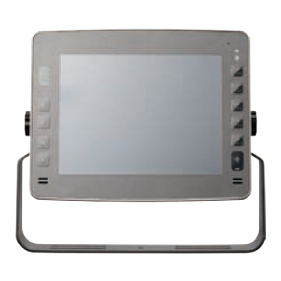
Chapter 1: Product Introduction Getting to Know VMC 3000 VMC 3000/4000 Series Front View VMC 3000/4000 Series Rear View Copyright © 2012 NEXCOM International Co., Ltd. All rights reserved VMC 3000/4000 Series User Manual... -
Page 28: Vmc 3000/3500
Chapter 1: Product Introduction VMC 3000/3500 VMC 3001/3501 Copyright © 2012 NEXCOM International Co., Ltd. All rights reserved VMC 3000/4000 Series User Manual... -
Page 29: Vmc 4000/Vmc 4500
Chapter 1: Product Introduction VMC 4000/VMC 4500 VMC 4001/VMC 4501 Copyright © 2012 NEXCOM International Co., Ltd. All rights reserved VMC 3000/4000 Series User Manual... - Page 30 34, 41 Power Output 14, 26, COM1 DB9 RS-232 connector with either 0, 5 or 12V on pin 9 for external devices. COM2 DB9 RS-232 connector. Copyright © 2012 NEXCOM International Co., Ltd. All rights reserved VMC 3000/4000 Series User Manual...
- Page 31 CAN and GPIO connector, Default: 2 x GPI and 2 x GPO Option: 1 x CANbus (Installing CAN module) The USB port complies with USB 2.0 specifications. (VMC 3000 Series) 17, 24, 30, 37 USB Port Dual USB port complies with USB 2.0 specifications. (VMC 4000 Series) The LAN port is an RJ45 interface with integrated LEDs and supports 10/100/1000Mbps Ethernet data transfer rates.
-
Page 32: External I/O Interface
Definition Definition Definition Definition GAL_GPO2_R GAL_GPI1_R SP_DCD_2 SP_RTS_2 GAL_GPO1_R CANH_GAL_GPI3 SP_RXD_2 SP_CTS_2 CANL_GAL_GPO3 C1708H_GAL_GPI4 SP_TXD_2 SP_RI_2 C1708L_GAL_GPO4 CH_GND SP_DTR_2 CH_GND CH_GND COM2_GND CH_GND GAL_GPI2_R SP_DSR_2 Copyright © 2012 NEXCOM International Co., Ltd. All rights reserved VMC 3000/4000 Series User Manual... -
Page 33: Com1 Rs-232 Connector
Connector size: DB-9 male port, 9-pin D-Sub Connector location: CN9 Definition Definition Definition Definition SP_DCD_1 SP_RTS_1 5V_OUT SP_RXD_1 SP_CTS_1 12V_OUT SP_TXD_1 COM_RI_PWR MSMB_CLK MSMB_DATA SP_DTR_1 CH_GND COM1_GND CH_GND SP_DSR_1 Copyright © 2012 NEXCOM International Co., Ltd. All rights reserved VMC 3000/4000 Series User Manual... -
Page 34: Power Input Connector
Chapter 1: Product Introduction Power Input Connector Connector location: CN9 Definition Definition VIN_GND1 IGNITION_F Copyright © 2012 NEXCOM International Co., Ltd. All rights reserved VMC 3000/4000 Series User Manual... -
Page 35: Vmc 3001/ 3501
Connector location: CN9 2 3 4 Definition Definition Definition Definition SP_DCD_1 SP_DSR_1 FRONT_L_F MIC_JD SP_RXD_1 SP_RTS_1 FRONT_JD AGND SP_TXD_1 SP_CTS_1 FRONT_R_F SP_DTR_1 COM_RI_PWR MIC_JD_F COM_GND Copyright © 2012 NEXCOM International Co., Ltd. All rights reserved VMC 3000/4000 Series User Manual... -
Page 36: Can And Gpio Connector
Chapter 1: Product Introduction CAN and GPIO Connector DC Input Connector Definition Definition Definition Definition GAL_GPIO_GND CAN_GND GAL_GPI1_R CAN1_L IGNITION_F GAL_GPO1_R CAN1_H GAL_GPI2_R C1708_1_L GAL_GPO2_R C1708_1_H Copyright © 2012 NEXCOM International Co., Ltd. All rights reserved VMC 3000/4000 Series User Manual... -
Page 37: Dc Output Connector
Chapter 1: Product Introduction DC Output Connector 2 3 4 Definition Definition MSMB_CLK 12V_OUT 5V_OUT MSMB_DATA Copyright © 2012 NEXCOM International Co., Ltd. All rights reserved VMC 3000/4000 Series User Manual... -
Page 38: External I/O Interface
SP_DTR_1 CH_GND CAN_ODOMETER SP_DSR_2 COM1_GND CH_GND C1708_2_H SP_DCD_2 SP_DSR_1 GAL_GPI1_R COM2_GND GAL_GPO1_R CAN_GND SP_TXD_3 CAN_GPIO22 COM2_TXD_+ CAN_DIRECTION COM2_RTS_+ GAL_GPIO_GND COM2_RXD_- COM3_GND CAN1_H CH_GND CAN1_L CH_GND Copyright © 2012 NEXCOM International Co., Ltd. All rights reserved VMC 3000/4000 Series User Manual... -
Page 39: 12V Power Output Connector
Chapter 1: Product Introduction 5V/12V Power Output Connector Power Input Connector Connector location: CN8 Connector location: CN9 Definition Definition Definition Definition 5V_OUT VIN_GND1 12V_OUT MSMB_CLK MSMB_DATA IGNITION_F Copyright © 2012 NEXCOM International Co., Ltd. All rights reserved VMC 3000/4000 Series User Manual... -
Page 40: Speaker-Out
Connector size: 3.5mm TRS Connector size: 3.5mm TRS Connector location: CN2 Connector location: CN1 Definition Definition Definition Definition SURR_OUT_R_CA SURR_OUT_L_CA MIC_OUT LINE_OUTD# AUDIO_GND MIC_JD AUDIO_GND AUDIO_GND AUDIO_GND Copyright © 2012 NEXCOM International Co., Ltd. All rights reserved VMC 3000/4000 Series User Manual... -
Page 41: Vmc 4001
Definition Definition SP_TXD_3 COM2_CTS_- SP_RXD_3 SP_DCD_1 IGNITION_F SP_DCD_2 SP_RXD_1 COM3_GND SP_TXD_1 COM2_TXD_+ SP_DTR_1 COM2_RXD_- COM1_GND COM2_GND SP_DSR_1 SP_DTR_2 SP_RTS_1 COM2_RTS_+ SP_CTS_1 SP_DSR_2 COM_RI_PWR SP_RI_2 COM_CH_GND Copyright © 2012 NEXCOM International Co., Ltd. All rights reserved VMC 3000/4000 Series User Manual... -
Page 42: Audio Connector
CAN and GPIO Connector 2 3 4 Definition Definition Definition Definition FRONT_L_F MIC_JD GAL_GPIO_GND CAN_GND FRONT_JD AGND GAL_GPI1_R CAN1_L FRONT_R_F GAL_GPO1_R CAN1_H MIC_JD_F GAL_GPI2_R C1708_1_L GAL_GPO2_R C1708_1_H Copyright © 2012 NEXCOM International Co., Ltd. All rights reserved VMC 3000/4000 Series User Manual... -
Page 43: Dc Output Connector
Chapter 1: Product Introduction DC Output Connector LAN Connector 2 3 4 Definition Definition Definition Definition MSMB_CLK LAN1_MDI_1N LAN1_MDI_1P 12V_OUT LAN1_MDI_2N LAN1_MDI_2P 5V_OUT LAN1_MDI_3N LAN1_MDI_3P MSMB_DATA LAN1_MDI_4N LAN1_MDI_4P Copyright © 2012 NEXCOM International Co., Ltd. All rights reserved VMC 3000/4000 Series User Manual... -
Page 44: Usb 2.0 Connector
Chapter 1: Product Introduction USB 2.0 Connector Definition Definition USB_D- USB_D+ USB_VCC USB_GND USB_D- USB_D+ USB_VCC USB_GND Copyright © 2012 NEXCOM International Co., Ltd. All rights reserved VMC 3000/4000 Series User Manual... -
Page 45: Chapter 2: System Setup
The power key can power on/off the system as well as turn on/off the display. System Power On Power Source Setup The typical power consumption requirement for VMC 3000/3001 series is 26W, for VMC3500/3501 series is 32W. Please select the right adapter or car battery to power on the VMC products. Power Key If the VMC does not have ignition signal, please use a cable to short the Vin and ignition pin. -
Page 46: Installing A Wlan Or Wwan Module
Chapter 2: System Setup Installing a WLAN or WWAN module 2. Remove the rear cover of the VMC 3000 series. The Mini PCI Express slot shown below is used to install a WLAN module or 3.5G communication module such as GPRS, UMTS or HSDPA module. -
Page 47: Installing A Sata Ssd Drive
1. Place the SSD drive into the tray and then tighten the four screws. 2. Connect the SATA data cable and the power cable to the SATA connector at the rear of the SSD drive. Copyright © 2012 NEXCOM International Co., Ltd. All rights reserved VMC 3000/4000 Series User Manual... - Page 48 3. Align the mounting holes on the tray to the mounting holes on the board, then tighten the screws to secure the drive to the chassis. Copyright © 2012 NEXCOM International Co., Ltd. All rights reserved VMC 3000/4000 Series User Manual...
-
Page 49: Installing A Can Bus Module
Push the module down then secure it with a mounting screw. 1. The pin header shown below is used to install a CAN Bus module. CAN Bus Module Push the module down Copyright © 2012 NEXCOM International Co., Ltd. All rights reserved VMC 3000/4000 Series User Manual... -
Page 50: Chapter 3: Using The Gps Feature
WAAS/EGNOS and power saving mode. 1. Go to Device Manager to ensure the device is installed correctly. 3. Follow the given instructions to complete the installation. Copyright © 2012 NEXCOM International Co., Ltd. All rights reserved VMC 3000/4000 Series User Manual... -
Page 51: Setup Window Screenshot
“VTG check box” - Some navigation or map software requires to receive VTG data output for during operation. Check the box to activate the VTG data output. Copyright © 2012 NEXCOM International Co., Ltd. All rights reserved VMC 3000/4000 Series User Manual... -
Page 52: Gps Info Window Screenshot
Time (hhmmss) Blue circle indicates that is being tracked and is being used in the cur- • rent position. Copyright © 2012 NEXCOM International Co., Ltd. All rights reserved VMC 3000/4000 Series User Manual... -
Page 53: Gps Information Instructions
Satellite status can be observed in the “GPS Info Window”. Use the “Tab Menu” to switch between Setup window and GPS info window. Please make sure to de-activate the GPS device before exiting this pro- gram. Copyright © 2012 NEXCOM International Co., Ltd. All rights reserved VMC 3000/4000 Series User Manual... -
Page 54: Chapter 4: Jumpers And Connectors For Vmc 3000 Series
This chapter describes how to set the jumpers on the motherboard. Note ponents. Humid environment tend to have less static electricity than dry that the following procedures are generic for all VMC 3000 series. environments. A grounding strap is warranted whenever danger of static electricity exists. -
Page 55: Jumper
Chapter 4: Jumpers and Connectors for VMC 3000 Series Jumper A jumper is the simplest kind of electric switch. It consists of two metal pins and a cap. When setting the jumpers, ensure that the jumper caps are placed on the correct pins. When the jumper cap is placed on both pins, the jumper is short. -
Page 56: Locations Of The Jumpers And Connectors
Chapter 4: Jumpers and Connectors for VMC 3000 Series Locations of the Jumpers and Connectors The figure below is the main board which is the board used in the VMC system. It shows the locations of the jumpers and connectors. -
Page 57: I/O Board
Chapter 4: Jumpers and Connectors for VMC 3000 Series The figure below is the IO board used in the VMC system. It shows the locations of the jumpers and connectors. I/O Board Waterproof I/O Board GFM1 Copyright © 2012 NEXCOM International Co., Ltd. All rights reserved... -
Page 58: Internal Connectors And Jumper Settings
Chapter 4: Jumpers and Connectors for VMC 3000 Series Internal Connectors and Jumper Settings Membrane Key FPC Connector Port 80 Connector Connector size: 1x30 30-pin header, 0.5mm pitch Connector size: 1mm Wafer 10-pin 180° Connector location: J4 Connector location: J6... -
Page 59: Canbus Input Connector
Chapter 4: Jumpers and Connectors for VMC 3000 Series CANbus Input Connector CANbus Output Connector Connector size: 2x5 10-pin header, 2.0mm pitch Connector size: 2x5 10-pin header, 2.0mm pitch Connector location: JP3 Connector location: JP2 Definition Definition Definition Definition CAN_TXD... -
Page 60: Gal Programmer Pin Header
Chapter 4: Jumpers and Connectors for VMC 3000 Series GAL Programmer PIN Header Touch Controller Connector Connector size: 1x6 6-pin header, 2.54mm pitch Connector size: 1x5 5-pin header, 2.54mm pitch Connector location: JP9 Connector location: JP8 Definition Definition Definition Definition... -
Page 61: Mcu Programmer Pin Header
Chapter 4: Jumpers and Connectors for VMC 3000 Series MCU Programmer Pin Header Backlight Control Connector Connector size: 1x5 5-pin header, 2.54mm pitch Connector size: 1x5 5-pin header, 2.0mm pitch Connector location: JP7 Connector location: J9 Definition Definition Definition Definition +3.3ALW... -
Page 62: Mcu Com Port
Chapter 4: Jumpers and Connectors for VMC 3000 Series MCU COM Port Temp Sensor Connector size: 1x3 3-pin header, 2.54mm pitch Connector size: 1x2 2-pin header Connector location: JP6 Connector location: JP5 Definition Definition SENSOR+ Copyright © 2012 NEXCOM International Co., Ltd. All rights reserved... -
Page 63: Serial-Ata
Chapter 4: Jumpers and Connectors for VMC 3000 Series Serial-ATA Serial-ATA Power Input Connector size: Standard Serial ATAII 7P (1.27mm, SATA-M-180) Connector size: 1x4 4-pin header Connector location: CN3 Connector location: CN7 Definition Definition Definition Definition SATA_TXP0 - SATA_TXN0 VCC5... -
Page 64: Mini-Pcie Connector (3.5G)
Chapter 4: Jumpers and Connectors for VMC 3000 Series Mini-PCIe Connector (3.5G) Connector location: CN5 Definition Definition Definition Definition MIC + +V3.3S MIC - SPK + USIM PWR RESET USIM DATa USB_D- VCC_MSM26_DIG USIM CLK USB_D+ USIM RST +V3.3S +V3.3S... -
Page 65: Mini-Pcie Connector (Wlan)
Chapter 4: Jumpers and Connectors for VMC 3000 Series Mini-PCIe Connector (WLAN) Connector location: CN8 Definition Definition Definition Definition WAKE# +V3.3S +V1.5S SMB_CLK +V1.5S PETn0 SMB_DATA CLKREQ# PETp0 USB_D- REFCLK- USB_D+ REFCLK+ LED_WWAN# LED_WLAN# DISABLE# LED_WPAN# PERST# +V1.5S PERn0 +3.3S PERp0 +V3.3S... -
Page 66: Sim Card Connectors
Chapter 4: Jumpers and Connectors for VMC 3000 Series SIM Card Connectors Connector location: CN6 and CN9 Definition Definition POWER VOLTAGE RESET SIGNAL CLOCK SIGNAL VPP:PROGRAM VOLTAGE Contact present switch Copyright © 2012 NEXCOM International Co., Ltd. All rights reserved... -
Page 67: Internal Connectors And Jumper Settings
Chapter 4: Jumpers and Connectors for VMC 3000 Series Internal Connectors and Jumper Settings I/O Board LAN Connector USB Connector Connector size: RJ45 port with LEDs Connector size: RJ45 port with LEDs Connector location: CN3 Connector location: CN4 Definition Definition... -
Page 68: Speaker-Out
Chapter 4: Jumpers and Connectors for VMC 3000 Series Speaker-out Mic-in Connector size: 3.5mm TRS Connector size: 3.5mm TRS Connector location: CN2 Connector location: CN1 Definition Definition Definition Definition SURR_OUT_R_CA SURR_OUT_L_CA MIC_OUT LINE_OUTD# AUDIO_GND MIC_JD AUDIO_GND AUDIO_GND AUDIO_GND Copyright © 2012 NEXCOM International Co., Ltd. All rights reserved... -
Page 69: Internal Connectors And Jumper Settings
Chapter 4: Jumpers and Connectors for VMC 3000 Series Internal Connectors and Jumper Settings Waterproof I/O Board Power Input Connector Power Output Connector Connector size: 1x3 3-pin header Connector size: 1x8 8-pin header Connector location: CN3 Connector location: J5 Definition... -
Page 70: Lan Connector
Chapter 4: Jumpers and Connectors for VMC 3000 Series LAN Connector LAN LED Connector size: 2x5 10-pin header Connector size: 1x4 4-pin header Connector location: CN2 Connector location: JP1 Definition Definition Definition Definition LAN_MDI_0P_R LAN_GND 3VSB 3VSB LAN_MDI_1P_R LAN_MDI_2P_R LAN_ACTLED#... -
Page 71: Usb Connector
Chapter 4: Jumpers and Connectors for VMC 3000 Series USB Connector Audio Connector Connector size: 1x5 5-pin header Connector size: 1x6 6-pin header Connector location: J1 Connector location: J2 Definition Definition Definition Definition USB0/1_FP CH_GND FRONT_L_F MIC_JD USB_0N_L FRONT_JD AGND... -
Page 72: Canbus Connector
Chapter 4: Jumpers and Connectors for VMC 3000 Series CANbus Connector COM1 Connector Connector size: 1x8 8-pin header Connector size: 2x5 10-pin header Connector location: J3 Connector location: CN1 Definition Definition Definition Definition CAN_GND C1708_1_L SP_DCD_1 SP_DSR_1 C1708_1_H SP_RXD_1 SP_RTS_1... -
Page 73: Chapter 5: Jumpers And Connectors For Vmc 4000 Series
Ground yourself before touching any internal components, by touching • Use correct screws and do not over tighten screws. a metal object. Static electricity can damage many of the electronic com- Copyright © 2012 NEXCOM International Co., Ltd. All rights reserved VMC 3000/4000 Series User Manual... -
Page 74: Jumper
(on) and open (off). Two-Pin Jumpers: Open (Left) and Short (Right) Three-Pin Jumpers: Pins 1 and 2 Are Short Copyright © 2012 NEXCOM International Co., Ltd. All rights reserved VMC 3000/4000 Series User Manual... -
Page 75: Locations Of The Jumpers And Connectors
Locations of the Jumpers and Connectors The figure below is the carry board used in the VMC system. It shows the locations of the jumpers and connectors. Carry Board CN12 Copyright © 2012 NEXCOM International Co., Ltd. All rights reserved VMC 3000/4000 Series User Manual... -
Page 76: Internal Connectors And Jumper Settings For Carry Board
Connector location: SW2 Connector location: SW4 9V~36V 10.4(*) Don’t Care SW4.1 all can start SW4.2 SW2.1 SW2.2 Don’t Care (*) Default Setting (*) Default Setting Copyright © 2012 NEXCOM International Co., Ltd. All rights reserved VMC 3000/4000 Series User Manual... -
Page 77: Gpio Setup Selection
GPIO Setup Selection Connector size: 4-pin DIP switch Connector location: SW3 2 3 4 GPIO GPIO Open Drain Pull High(*) SW3.1 SW3.2 SW3.3 SW3.4 (*) Default Setting Copyright © 2012 NEXCOM International Co., Ltd. All rights reserved VMC 3000/4000 Series User Manual... -
Page 78: Jumper Settings
Connector size: 1x5 5-pin header Connector location: JP1 Connector location: JP7 Status Definition Definition Definition 1-2(*) Short* VBAT IN +V3.3ALW C2CK Short Clear CMOS MRST Copyright © 2012 NEXCOM International Co., Ltd. All rights reserved VMC 3000/4000 Series User Manual... -
Page 79: Gal Download
GAL Download MCU COM Port Connector size: 1x6 6-pin header Connector size: 1x3 3-pin header Connector location: JP9 Connector location: JP6 Definition Definition Definition +V3.3S Copyright © 2012 NEXCOM International Co., Ltd. All rights reserved VMC 3000/4000 Series User Manual... -
Page 80: Ec Download
Connector size: 1x8 8-pin header Connector size: 1x6 6-pin header Connector location: JP5 Connector location: JP5 Definition Definition Definition Definition +V3.3 EC_TDI VCC3 EC_TMS EC_TCK RDY# EC_TDO RDY# Copyright © 2012 NEXCOM International Co., Ltd. All rights reserved VMC 3000/4000 Series User Manual... -
Page 81: Mcu Programmer Pin Header
Connector size: 1x6 6-pin header Connector size: 1x5 5-pin header, 2.0mm pitch Connector location: JP7 Connector location: J9 Definition Definition Definition Definition +3.3ALW Panel_backlight MRST C2CK L_BLK_ADJ BLK_ADJ_RE L_BLK_EN Copyright © 2012 NEXCOM International Co., Ltd. All rights reserved VMC 3000/4000 Series User Manual... -
Page 82: Serial-Ata Power Input
Connector size: 1x4 4-pin header Connector size: Standard Serial ATA 7P (1.27mm, SATA-M-180) Connector location: CN7 Connector location: CN3 Definition Definition Definition Definition VCC12 SATA_TX0P VCC5 SATA_TX0N SATA_RX0N SATA_RX0P Copyright © 2012 NEXCOM International Co., Ltd. All rights reserved VMC 3000/4000 Series User Manual... -
Page 83: Usb
F2 KEY F1 KEY VOLUME UP KEY VOLUME DOWN KEY PANEL BRIGHTNESS UP KEY PANEL BRIGHTNESS DOWN PWR ON LED PWR PWR ON LED POWER BOTTOM Copyright © 2012 NEXCOM International Co., Ltd. All rights reserved VMC 3000/4000 Series User Manual... -
Page 84: Speaker Connector
Reset Button Connector size: 1x2 2-pin header, 1.0mm pitch Connector location: SW1 Connector location: J10 and J1 Definition Definition RST_BTN# FRONT_A_L+_RF FRONT_A_L-_RF Definition FRONT_A_R+_RF FRONT_A_R-_RF Copyright © 2012 NEXCOM International Co., Ltd. All rights reserved VMC 3000/4000 Series User Manual... -
Page 85: Rtc Battery Connector
Connector type: 1x2 2-pin header Connector type: 1x6 JST, 6-pin header Connector location: J2 Connector location: J14 Definition Definition Definition GPS_BAT Power_LED VBAT1 GPS_TXD3 GPS_TXD3 VCC3 Copyright © 2012 NEXCOM International Co., Ltd. All rights reserved VMC 3000/4000 Series User Manual... -
Page 86: Canbus Input Connector
Connector size: 2x5 10-pin header Connector location: JP3 Connector location: JP2 Definition Definition Definition Definition CAN_TXD CAN_RXD CAN1_H C1708_1_H CAN_DI CAN_DO CAN1_L C1708_1_L VCC_CAN CAN_12V Copyright © 2012 NEXCOM International Co., Ltd. All rights reserved VMC 3000/4000 Series User Manual... -
Page 87: Vmc 4000 I/O Board
Chapter 5: Jumpers and Connectors for VMC 4000 Series VMC 4000 I/O Board CN1 CN2 Copyright © 2012 NEXCOM International Co., Ltd. All rights reserved VMC 3000/4000 Series User Manual... -
Page 88: Rs232/485/422 Mode Selection For Com2
SW1.1 SP_RXD_2 RS485_- SW1.2 SP_RTS_2 RS422_TX+ SW1.3 SP_CTS_2 RS422_TX- SW1.4 COM2_CTS_- COM2_CTS_- SW1.5 COM2_RTS_+ COM2_RTS_+ SW1.6 COM2_RXD_- COM2_RXD_- SW1.7 COM2_TXD_+ COM2_TXD_+ SW1.8 (*) Default Setting Copyright © 2012 NEXCOM International Co., Ltd. All rights reserved VMC 3000/4000 Series User Manual... -
Page 89: Canbus/Gps Dr Mode Selection
SW3.1 C1708_1_L ODOMETER SW3.2 CAN2_H GPIO22_GPS SW3.3 CAN2_L DIRECTION SW3.4 CAN_DIRECTION CAN_DIRECTION SW3.5 CAN_GPIO22 CAN_GPIO22 SW3.6 CAN_ODOMETER CAN_ODOMETER SW3.7 CAN_GPS CAN_GPS SW3.8 (*) Default Setting Copyright © 2012 NEXCOM International Co., Ltd. All rights reserved VMC 3000/4000 Series User Manual... -
Page 90: Com1 Ri/Power Switch
SP_RI_1 VGA_BLUE VGA_GND COM_RI_PWR COM_RI_PWR VGA_GND RGB_GND COM_RI_PWR COM_RI_PWR RGB_GND RGB_GND VGA_+5V VGA_GND VGA_GND VGA_DATA VGA_HS VGA_VS VGA_CLK SW2.1 SW2.2 SW2.3 SW2.4 (*) Default Setting Copyright © 2012 NEXCOM International Co., Ltd. All rights reserved VMC 3000/4000 Series User Manual... -
Page 91: Canbus Input Connector
Connector size: 2x5 10-pin header Connector size: 2x5 10-pin header Connector location: JP2 Connector location: JP1 Definition Definition Definition Definition CAN2_TXD CAN2_RXD CAN2_H C1708_2_H GAL_GPO4_DI GAL_GPI4_DO CAN2_L C1708_2_L CAN_VCC Copyright © 2012 NEXCOM International Co., Ltd. All rights reserved VMC 3000/4000 Series User Manual... -
Page 92: Usb Connector
Chapter 5: Jumpers and Connectors for VMC 4000 Series USB Connector Connector size: 1x4 4-pin header Connector location: J1 Definition Definition USB0/1_FP USB_0# USB_0 UGND_2 Copyright © 2012 NEXCOM International Co., Ltd. All rights reserved VMC 3000/4000 Series User Manual... -
Page 93: Vmc 4001 Waterproof I/O Board
Chapter 5: Jumpers and Connectors for VMC 4000 Series VMC 4001 Waterproof I/O Board Copyright © 2012 NEXCOM International Co., Ltd. All rights reserved VMC 3000/4000 Series User Manual... -
Page 94: Gpio1.2/Can2 Mode Selection
SW1.1 GAL_GPO2_R C1708_2_H SW1.2 GAL_GPI2_R CAN2_H SW1.3 GAL_GPI1_R CAN2_L SW1.4 GPI1_CANL GPI1_CANL SW1.5 GPI2_CANH GPI2_CANH SW1.6 GPO2_C1708H GPO2_C1708H SW1.7 GPO1_C1708L GPO1_C1708L SW1.8 (*) Default Setting Copyright © 2012 NEXCOM International Co., Ltd. All rights reserved VMC 3000/4000 Series User Manual... -
Page 95: Rs232/Rs485/Rs422 Mode Selection For Com2
SW1.1 SP_RTS_2 RS422_TX+ SW1.2 SP_RXD_2 RS485_- SW1.3 SP_TXD_2 RS485_+ SW1.4 COM2_TXD_+ COM2_TXD_+ SW1.5 COM2_RXD_- COM2_RXD_- SW1.6 COM2_RTS_+ COM2_RTS_+ SW1.7 COM2_CTS_- COM2_CTS_- SW1.8 (*) Default Setting Copyright © 2012 NEXCOM International Co., Ltd. All rights reserved VMC 3000/4000 Series User Manual... -
Page 96: Com1 Ri/Power Switch
Connector location: CN2 1 2 3 4 Definition Definition Definition COM_12V COM_5V IGNITION_F SP_RI_1 VIN_GND1 COM_RI_PWR COM_RI_PWR COM_RI_PWR COM_RI_PWR SW2.1 SW2.2 SW2.3 SW2.4 (*) Default Setting Copyright © 2012 NEXCOM International Co., Ltd. All rights reserved VMC 3000/4000 Series User Manual... -
Page 97: Power Output Connector
Connector size: 1x8 8-pin header Connector size: 1x4 4-pin header Connector location: J11 Connector location: J7 Definition Definition Definition Definition MSMB_DATA MSMB_DATA USB_2# USB_2 USB2/3_FP UGND_2 5V_OUT 12V_OUT 12V_OUT Copyright © 2012 NEXCOM International Co., Ltd. All rights reserved VMC 3000/4000 Series User Manual... -
Page 98: Usb Connector
Connector size: 1x6 6-pin header Connector location: J6 Connector location: J10 Definition Definition Definition Definition USB_3# USB_3 FRONT_L_F FRONT_JD USB2/3_FP UGND_3 FRONT_R_F MIC_JD_F MIC_JD AGND AGND AGND Copyright © 2012 NEXCOM International Co., Ltd. All rights reserved VMC 3000/4000 Series User Manual... -
Page 99: Lan1 Connector
Connector size: 1x4 4-pin header Connector size: 1x4 4-pin header Connector location: J3 Connector location: J4 Definition Definition Definition Definition LAN_MDI_0P_R LAN_MDI_0N_R LAN_MDI_2P_R LAN_MDI_2N_R LAN_MDI_1P_R LAN_MDI_1N_R LAN_MDI_3P_R LAN_MDI_3N_R Copyright © 2012 NEXCOM International Co., Ltd. All rights reserved VMC 3000/4000 Series User Manual... -
Page 100: Lan2 Connector
Connector size: 1x4 4-pin header Connector size: 1x4 4-pin header Connector location: J2 Connector location: J1 Definition Definition Definition Definition LAN1_MDI_0P_R LAN1_MDI_0N_R LAN1_MDI_2P_R LAN1_MDI_2N_R LAN1_MDI_1P_R LAN1_MDI_1N_R LAN1_MDI_3P_R LAN1_MDI_3N_R Copyright © 2012 NEXCOM International Co., Ltd. All rights reserved VMC 3000/4000 Series User Manual... -
Page 101: Lan Led Connector
Connector size: 1x10 10-pin header Connector location: J5 Connector location: J9 Definition Definition Definition Definition 3VSB LAN_ACTLED# CAN1_L CAN1_H 3VSB C1708_1_L C1708_1_L LAN1_ACTLED# CAN_GPIO_GND GPI1_CANL GPI2_CANH GPO1_C1708L GPO1_C1708L CAN_GPIO_GND Copyright © 2012 NEXCOM International Co., Ltd. All rights reserved VMC 3000/4000 Series User Manual... -
Page 102: Canbus Input Connector
Connector size: 2x5 10-pin header Connector size: 2x5 10-pin header Connector location: JP1 Connector location: JP2 Definition Definition Definition Definition CAN2_TXD CAN2_RXD CAN2_H C1708_2_H GAL_GPO4_DI GAL_GPI4_DO CAN2_L C1708_2_L CAN_VCC Copyright © 2012 NEXCOM International Co., Ltd. All rights reserved VMC 3000/4000 Series User Manual... -
Page 103: Vga Connector
VGA_GND RGB_GND COM2_TXD_+ COM2_RXD_- VGA_BLUE RGB_GND COM2_GND SP_DTR_2 COM2_RTS_+ SP_DSR_2 VGA_GREEN RGB_GND SP_RI_2 COM2_CTS_- VGA_RED SP_DCD_1 SP_RXD_1 SP_TXD_1 SP_DTR_1 COM1_GND SP_DSR_1 SP_RTS_1 SP_CTS_1 COM_RI_PWR COM_CH_GND Copyright © 2012 NEXCOM International Co., Ltd. All rights reserved VMC 3000/4000 Series User Manual... -
Page 104: Chapter 6: Function Key Code Constants
“How to capture a pressed function keys”, please refer to the Microsoft technical support website http://support.microsoft.com/kb/822492/en-us Key code value for ActionScript 2.0 in Adobe Flash http://help.adobe.com/en_US/AS2LCR/Flash_10.0/help.html?content=00000520.html Copyright © 2012 NEXCOM International Co., Ltd. All rights reserved VMC 3000/4000 Series User Manual... -
Page 105: Extended Ascii Keyboard Codes
00111100 F3 key 00111101 F4 key 00111110 F5 key 0011111 F6 key 01000000 F7 key 01000001 F8 key 01000010 F9 key 01000011 F10 key 01000100 Copyright © 2012 NEXCOM International Co., Ltd. All rights reserved VMC 3000/4000 Series User Manual... -
Page 106: Chapter 7: Touchscreen Installation Guide
The touchscreen support the following operating systems: O.S. Linux 2000/XP/2003/VISTA/7/8 (Kernel 2.6 & X-Windows Win CE (4.2/5.0/6.0/7.0) Mode) Driver USB Driver Copyright © 2012 NEXCOM International Co., Ltd. All rights reserved VMC 3000/4000 Series User Manual... -
Page 107: Install Penmount Windows Universal Driver (For 2000/Xp/Xpt/Xpe/2003/Vista/7/Wes7/2008/8)
0, 5, 10, 15, 20, 25, 30 are the default values for edge compensation. Smoothing 1. Turn on the smoothing function. 0. Turn off the smoothing function. Copyright © 2012 NEXCOM International Co., Ltd. All rights reserved VMC 3000/4000 Series User Manual... - Page 108 ; TouchReport =2, it will not be installed as Digitizer mode directly in Windows 7, the user can select Digitizer or mouse mode during the installation procedure. ; COM1=PCI,38400, it will not install the driver at COM1 permanently. Copyright © 2012 NEXCOM International Co., Ltd. All rights reserved VMC 3000/4000 Series User Manual...
-
Page 109: Install Penmount Mouse Driver In Windows 2000/Xp/Xpt/Xpe/2003/Vista/7/Wes7/2008/8
8. Then restart operating system. As soon as driver installation finishes, both the icons of PenMount Monitor and Gesture AP show up in the notification area. Copyright © 2012 NEXCOM International Co., Ltd. All rights reserved VMC 3000/4000 Series User Manual... -
Page 110: Install Penmount Digitizer Driver In Windows Xpt/Vista/7/Wes7/2008/8
On PenMount Control Panel you are able to see the device of PenMount 6000 USB/RS-232 detected by your system under Device tab. Select a device and click the Configure button. Copyright © 2012 NEXCOM International Co., Ltd. All rights reserved VMC 3000/4000 Series User Manual... -
Page 111: Penmount Control Panel
E.g. Please run ms-dos prompt or command prompt. c:\Program Files\PenMount Universal Driver\DMCCtrl.exe -calibration 4 (Standard Calibration) DMCCtrl.exe - calibration ($) 4=Standard Calibration 4 9=Advanced Calibration 9 16=Advanced Calibration 16 25=Advanced Calibration 25 Copyright © 2012 NEXCOM International Co., Ltd. All rights reserved VMC 3000/4000 Series User Manual... - Page 112 NOTE: The older a touchscreen is, the more calibration points of the Advanced Mode it needs. For an optimal accuracy we suggest to use a stylus to make the advanced calibration. Copyright © 2012 NEXCOM International Co., Ltd. All rights reserved VMC 3000/4000 Series User Manual...
- Page 113 Beep on both beep occurs when comes down and is lifted up. Beep Frequency modifies sound frequency. Beep Duration modifies sound duration. Copyright © 2012 NEXCOM International Co., Ltd. All rights reserved VMC 3000/4000 Series User Manual...
- Page 114 Edge Compensation This page is the edge compensation settings. You can adjust the settings from 0 to 30 for accommodating the difference of each touch panel. Copyright © 2012 NEXCOM International Co., Ltd. All rights reserved VMC 3000/4000 Series User Manual...
-
Page 115: Penmount Monitor Menu Icon
When you select this function, a mouse icon appears in the right-bottom of the screen. Click this icon to switch between Right and Left Button functions. Exit Exits the PenMount Monitor function. Copyright © 2012 NEXCOM International Co., Ltd. All rights reserved VMC 3000/4000 Series User Manual... -
Page 116: The Touchscreen Configure Of Penmount Digitizer Driver
Configure button. The calibration screen will appear automatically. Touch this point and rotation is mapped. NOTE: Rotate function is disabled if you use Monitor Mapping. Copyright © 2012 NEXCOM International Co., Ltd. All rights reserved VMC 3000/4000 Series User Manual... -
Page 117: Penmount Control Panel
25= Advanced Calibration 25 Calibrate This function offers two ways to calibrate your touchscreen. ‘Standard Calibration’ adjusts most touchscreens while ‘Advanced Calibration’ adjusts aging touchscreens. Copyright © 2012 NEXCOM International Co., Ltd. All rights reserved VMC 3000/4000 Series User Manual... - Page 118 NOTE: The older a touchscreen is, the more calibration points of the Advanced Mode it needs. For an optimal accuracy we suggest to use a stylus to make the advanced calibration. Copyright © 2012 NEXCOM International Co., Ltd. All rights reserved VMC 3000/4000 Series User Manual...
- Page 119 Edge Compensation This page is the edge compensation settings. You can adjust the settings from 0 to 30 for accommodating the difference of each touch panel. Copyright © 2012 NEXCOM International Co., Ltd. All rights reserved VMC 3000/4000 Series User Manual...
-
Page 120: Uninstall Penmount Windows Universal Driver
7.1.8 Uninstall PenMount Windows Universal Driver 1. Go to Control Panel. Click “Add/Remove program”. Select ”PenMount Universal Driver”. Click “Change/Remove” button. 2. Select ‘Uninstall’ to remove PenMount Windows Universal Driver. Copyright © 2012 NEXCOM International Co., Ltd. All rights reserved VMC 3000/4000 Series User Manual... -
Page 121: Install Penmount Linux X Window Usb Driver
Red Hat 7.3/8.0 OpenSuse 10.1/ 10.2/ 10.3/ 11/ 11.1/ 11.2/ 11.3/ 11.4/ 12.1 32_64bit Suse 10.0 Suse 9.2/9.3 Suse 8.0/9.0/9.1 Copyright © 2012 NEXCOM International Co., Ltd. All rights reserved VMC 3000/4000 Series User Manual... -
Page 122: Install Penmount Wince Driver
Before installing PenMount WinCE Driver, you must have WinCE system installed and running in your device. 7.3.1 Install PenMount WinCE Driver Please see the readme file included in the driver folder. Copyright © 2012 NEXCOM International Co., Ltd. All rights reserved VMC 3000/4000 Series User Manual... -
Page 123: Chapter 8: Touchscreen Driver Software Functions
Edge Compensation button or pressing the application key on Refresh the keyboard) will be supported. Copyright © 2012 NEXCOM International Co., Ltd. All rights reserved VMC 3000/4000 Series User Manual... - Page 124 Enable/configure Gesture AP to support PenMount gestures recognition. Screen Rotation Monitor The function supports nVidia, Intel, SMI or ATI and software such as Portrait Pivot Pro rotation automatic detection. Copyright © 2012 NEXCOM International Co., Ltd. All rights reserved VMC 3000/4000 Series User Manual...
-
Page 125: Standard Calibration
Our rotation configuration function allows you to easily match the touchscreen when you rotate your monitor. Copyright © 2012 NEXCOM International Co., Ltd. All rights reserved VMC 3000/4000 Series User Manual... - Page 126 Select Clear Screen to clear drawing. Show Pen Location is to show the locations where pen comes down and lifted up on the monitor. Select Exit to quit draw function. Copyright © 2012 NEXCOM International Co., Ltd. All rights reserved VMC 3000/4000 Series User Manual...
-
Page 127: Mouse Operation Mode
The drivers let the user adjust the desired touch- from appearing when using the touchscreen. The cursor appears when user screen sound, as well as turn the sound off. turns this function off. Copyright © 2012 NEXCOM International Co., Ltd. All rights reserved VMC 3000/4000 Series User Manual... -
Page 128: Cursor Offset
Refresh button on PenMount Control Panel to detect the newly attached PenMount devices. (Note: Refresh is only supported by PenMount Windows Universal Driver (for Windows 2000/XP/2003/VISTA).) Copyright © 2012 NEXCOM International Co., Ltd. All rights reserved VMC 3000/4000 Series User Manual... - Page 129 Chapter 8: Touchscreen Driver Software Functions Copyright © 2012 NEXCOM International Co., Ltd. All rights reserved VMC 3000/4000 Series User Manual...
-
Page 130: Chapter 9: Penmount Gesture Ap For Windows
PenMount Gesture AP icon shows up in the notification area. PenMount Gesture AP is running. the notification area. See the illustration below. PenMount Gesture AP is running. PenMount Gesture AP Enabled Disabled Copyright © 2012 NEXCOM International Co., Ltd. All rights reserved VMC 3000/4000 Series User Manual... -
Page 131: Configure Penmount Gesture Ap
Select Tools tab and click Gesture Setting button in PenMount Control Panel. 3. 15 PenMount Gestures are provided in total. PenMount Gestures for Windows XP Copyright © 2012 NEXCOM International Co., Ltd. All rights reserved VMC 3000/4000 Series User Manual... - Page 132 Chapter 9: PenMount Gesture AP for Windows In the [Gesture Setting] window, you can proceed to configure PenMount Gesture AP: See picture below. PenMount Gestures for Windows Vista / 7/ 8 Copyright © 2012 NEXCOM International Co., Ltd. All rights reserved VMC 3000/4000 Series User Manual...
-
Page 133: Penmount Gestures' Default Values In Windows Xp
(Alt + F4) to finger movement on the touch screen and the tapping will not trigger any program action. However, the gesture recognition is still functioning.) Copyright © 2012 NEXCOM International Co., Ltd. All rights reserved VMC 3000/4000 Series User Manual... -
Page 134: Chapter 10: Hotkey Setup Procedure
Chapter 10: Hotkey Setup Procedure Chapter 10: Hotkey Setup Procedure Installing NEXCOM Function Key App 1. Double click “HotkeyAPP.exe” Copyright © 2012 NEXCOM International Co., Ltd. All rights reserved VMC 3000/4000 Series User Manual... - Page 135 Chapter 10: Hotkey Setup Procedure 2. Select the installation folder and complete the installation. Copyright © 2012 NEXCOM International Co., Ltd. All rights reserved VMC 3000/4000 Series User Manual...
-
Page 136: Applying Administrator Authority
2. Switch to the Compatibility tab, then check “Run this program as an administrator”. Click “OK”, then execute “Hotkey.exe”. 1. Right click “Hotkey.exe” in installation folder, then select “properties”. Copyright © 2012 NEXCOM International Co., Ltd. All rights reserved VMC 3000/4000 Series User Manual... -
Page 137: Setup Hotkey Function
Chapter 10: Hotkey Setup Procedure Setup Hotkey Function 1. Right click “F1 icon” in system bar, then select “Open AP”. 2. Select function from dropdown list, F1 to F10 Copyright © 2012 NEXCOM International Co., Ltd. All rights reserved VMC 3000/4000 Series User Manual... -
Page 138: Setup Hotkey Function - User Define
Setup Hotkey Function - User Define 1. Select “User define” from dropdown list 2. Select application program via button. The “Executed file Path” will show the complete path. Copyright © 2012 NEXCOM International Co., Ltd. All rights reserved VMC 3000/4000 Series User Manual... -
Page 139: How To Switch Hotkey Button
How to Switch Hotkey Button Normal mode: Shift mode: Shift function inactive Shift function active Hotkey = F1 to F5 Hotkey = F6 to F10 Copyright © 2012 NEXCOM International Co., Ltd. All rights reserved VMC 3000/4000 Series User Manual... -
Page 140: Appendix A: I/O Address Function
0: Car Battery is OK 1: Car Battery is Low voltage Bit 4: Status of +12V output 0: circuit normal(under 4A) 1: over circuit(over 4A) Copyright © 2012 NEXCOM International Co., Ltd. All rights reserved VMC 3000/4000 Series User Manual... - Page 141 Bit 7 Bit 6 Bit 5 Bit 4 Bit 3 Bit 2 Bit1 Bit 0 Description 8 bits data (Bit 7 is highest bit of data) Copyright © 2012 NEXCOM International Co., Ltd. All rights reserved VMC 3000/4000 Series User Manual...
- Page 142 Bit 3: status of smart battery Bit0~3: GPO0~3 0: no discharging Bit4~7: GPI0~3 1: discharging Bit 4: status of FAN R? 0: well 1: failed Copyright © 2012 NEXCOM International Co., Ltd. All rights reserved VMC 3000/4000 Series User Manual...
- Page 143 Bit3: By Pass Car battery power 0: DISABLE 1: ENABLE(*) Auto clear WDT timer when read/write I/O port 0EE5H. Bit4: Wake on 3.5G MODULE 0: DISABLE(*) 1: ENABLE Copyright © 2012 NEXCOM International Co., Ltd. All rights reserved VMC 3000/4000 Series User Manual...
- Page 144 30 sec 1 min 1 min 5 min 5 min 10 min 10 min 15 min 15 min 30 min 30 min 1 hour 1 hour Copyright © 2012 NEXCOM International Co., Ltd. All rights reserved VMC 3000/4000 Series User Manual...
- Page 145 BIT1~0 Input Voltage 24V Startup Shutdown Startup Shutdown 11.5V 10.5V Startup Shutdown Startup Shutdown Startup Shutdown Startup Shutdown 12.5V Startup Shutdown Startup Shutdown 12.5V 11.5V Copyright © 2012 NEXCOM International Co., Ltd. All rights reserved VMC 3000/4000 Series User Manual...
- Page 146 Bit0~7: the hour value (hexadecimal) 0: No data transfer 1: Data link (auto detect) I/O port: 0EEFH (User setting time) Bit0~7: the minute value (hexadecimal) Copyright © 2012 NEXCOM International Co., Ltd. All rights reserved VMC 3000/4000 Series User Manual...
- Page 147 Bit 7 Bit 6 Bit 5 Bit 4 Bit 3 Bit 2 Bit1 Bit 0 Description 8 bits data (Bit 7 is highest bit of data) Copyright © 2012 NEXCOM International Co., Ltd. All rights reserved VMC 3000/4000 Series User Manual...
-
Page 148: Vmc 4000 Series
Bit 2: Ignition (read only) 0: OFF 1: ON Bit 3: Status of Car Battery 0: Car Battery is OK 1: Car Battery is Low voltage Copyright © 2012 NEXCOM International Co., Ltd. All rights reserved VMC 3000/4000 Series User Manual... - Page 149 Bit 6 Bit 5 Bit 4 Bit 3 Bit 2 Bit 1 Bit 0 Description 8 bits data (Bit 7 is highest bit of data) Copyright © 2012 NEXCOM International Co., Ltd. All rights reserved VMC 3000/4000 Series User Manual...
- Page 150 0: Battery capacity >= 10% 1: Battery capacity <= 10% Bit0~3: GPO0~2 Bit4~7: GPI0~2 Bit 4: Output Type 0: Use Car Battery 1: Use Backup Battery Copyright © 2012 NEXCOM International Co., Ltd. All rights reserved VMC 3000/4000 Series User Manual...
- Page 151 0110 0111 0: DISABLE 1000 1: ENABLE(*) Auto clear WDT timer when read/write I/O port 0EE5H. Bit4: Wake on 3.5G MODULE 0: DISABLE(*) 1: ENABLE Copyright © 2012 NEXCOM International Co., Ltd. All rights reserved VMC 3000/4000 Series User Manual...
- Page 152 1 min 1 min 5 min 5 min 10 min 10 min 30 min 15 min 1 hour 30 min 6 hour 1 hour 18 hour Copyright © 2012 NEXCOM International Co., Ltd. All rights reserved VMC 3000/4000 Series User Manual...
- Page 153 BIT1~0 Input Voltage 24V Startup Shutdown Startup Shutdown 11.5V 10.5V Startup Shutdown Startup Shutdown Startup Shutdown Startup Shutdown 12.5V Startup Shutdown Startup Shutdown 12.5V 11.5V Copyright © 2012 NEXCOM International Co., Ltd. All rights reserved VMC 3000/4000 Series User Manual...
- Page 154 Bit4: CANBUS Data link detect 0: No data transfer I/O port: 0EEFH (User setting time) 1: Data link (auto detect) Bit0~7: the minute value (hexadecimal) Copyright © 2012 NEXCOM International Co., Ltd. All rights reserved VMC 3000/4000 Series User Manual...
- Page 155 Bit 6 Bit 5 Bit 4 Bit 3 Bit 2 Bit 1 Bit 0 Description 8 bits data (Bit 7 is highest bit of data) Copyright © 2012 NEXCOM International Co., Ltd. All rights reserved VMC 3000/4000 Series User Manual...
- Page 156 001: VMC 010: nROK Bit1: GPS_PWR_EN 0: Disable Bit 0-4: Model 1: Enable (*) Currently VMC 3000-C1 is 00000 = 3000 ; 00001 = 3000C1 Bit2: Modem_PWR_EN Bit 0-4: 00001 0: ON (*) Bit 5-7: 001 1: OFF Bit3: Modem_SEL...
-
Page 157: Appendix B: Vehicle Power Management Setup
F4: Save & Exit F4: Save & Exit ESC: Exit ESC: Exit Version 2.10.1208. Copyright (C) 2010 American Megatrends, Inc. Version 2.10.1208. Copyright (C) 2010 American Megatrends, Inc. Copyright © 2012 NEXCOM International Co., Ltd. All rights reserved VMC 3000/4000 Series User Manual... -
Page 158: Vehicle Power Management Setup
F4: Save & Exit F4: Save & Exit ESC: Exit ESC: Exit Version 2.10.1208. Copyright (C) 2010 American Megatrends, Inc. Version 2.10.1208. Copyright (C) 2010 American Megatrends, Inc. Copyright © 2012 NEXCOM International Co., Ltd. All rights reserved VMC 3000/4000 Series User Manual... - Page 159 +/-: Change Opt. F1: General Help F2: Previous Values F3: Optimized Defaults F4: Save & Exit ESC: Exit Version 2.10.1208. Copyright (C) 2010 American Megatrends, Inc. Copyright © 2012 NEXCOM International Co., Ltd. All rights reserved VMC 3000/4000 Series User Manual...
- Page 160 +/-: Change Opt. F1: General Help F2: Previous Values F3: Optimized Defaults F4: Save & Exit ESC: Exit Version 2.10.1208. Copyright (C) 2010 American Megatrends, Inc. Copyright © 2012 NEXCOM International Co., Ltd. All rights reserved VMC 3000/4000 Series User Manual...
- Page 161 +/-: Change Opt. F1: General Help F2: Previous Values F3: Optimized Defaults F4: Save & Exit ESC: Exit Version 2.10.1208. Copyright (C) 2010 American Megatrends, Inc. Copyright © 2012 NEXCOM International Co., Ltd. All rights reserved VMC 3000/4000 Series User Manual...
- Page 162 ↑↓: Select Item 1 hour Power Off Delay Enter: Select Version 2.10.1208. Copyright (C) 2010 American Megatrends, Inc. +/-: Change Opt. F1: General Help F2: Previous Values Copyright © 2012 NEXCOM International Co., Ltd. All rights reserved VMC 3000/4000 Series User Manual...
- Page 163 Power Off Delay Enter: Select Version 2.10.1208. Copyright (C) 2010 American Megatrends, Inc. Delay Off Time selection +/-: Change Opt. F1: General Help F2: Previous Values Copyright © 2012 NEXCOM International Co., Ltd. All rights reserved VMC 3000/4000 Series User Manual...
-
Page 164: Appendix C: Power Consumption
Appendix C: Power Consumption Appendix C: Power Consumption Test Equipment/Tool DUT#1: VMC 3000 with 8GB SSD, 3.5G MC8790V, WLAN-QCOM Q802XKN, CFAST CARD and CAN BUS module DUT#2: VMC 3000 with 8GB SSD Windows 7 Burn-in software: version 5.3 Test Condition... - Page 165 1. Start all function at DUT and measure power consumption. 2. Get system into suspend mode and measure power consumption. Unit DUT#1 2.57A 0.28A 0.007A 0.007A DUT#2 2.30A 0.34A 0.012A 0.012A * Device: N/A Copyright © 2012 NEXCOM International Co., Ltd. All rights reserved VMC 3000/4000 Series User Manual...
-
Page 166: Appendix D: Sms And Dial Wake-Up Setting
F4: Save & Exit F4: Save & Exit ESC: Exit ESC: Exit Version 2.14.1219. Copyright (C) 2011 American Megatrends, Inc. Version 2.14.1219. Copyright (C) 2011 American Megatrends, Inc. Copyright © 2012 NEXCOM International Co., Ltd. All rights reserved VMC 3000/4000 Series User Manual... -
Page 167: Appendix E: Rtc Wake-Up Setting
F4: Save & Exit F4: Save & Exit ESC: Exit ESC: Exit Version 2.14.1219. Copyright (C) 2011 American Megatrends, Inc. Version 2.14.1219. Copyright (C) 2011 American Megatrends, Inc. Copyright © 2012 NEXCOM International Co., Ltd. All rights reserved VMC 3000/4000 Series User Manual... - Page 168 (5) After you have finished with the Setup, press <ESC> to go back to the main menu and then press “Enter” on “Save Changes and Reset.” Copyright © 2012 NEXCOM International Co., Ltd. All rights reserved VMC 3000/4000 Series User Manual...
-
Page 169: Appendix F: Auto Backlight Setting
“Enter” on “Save Changes and Reset.” After the setup procedure is completed, the light sensors can auto-adjust a display’s backlight. Copyright © 2012 NEXCOM International Co., Ltd. All rights reserved VMC 3000/4000 Series User Manual... -
Page 170: Appendix G: Bios Update
(1) Locate the “afuwin32” setup file in the “afuwin32” folder. (3) Press the “OK” button when prompted with a pop-up window. (2) Start the “afuwingui” setup program. Copyright © 2012 NEXCOM International Co., Ltd. All rights reserved VMC 3000/4000 Series User Manual... - Page 171 Appendix G: BIOS Update (4) Press the “Open” button. (5) Select the BIOS file. Copyright © 2012 NEXCOM International Co., Ltd. All rights reserved VMC 3000/4000 Series User Manual...
- Page 172 (6) Check all the options in “Block Options” and then press the “Flash” (7) The BIOS will be updated automatically, when the update is completed, button. please restart the VMC. Copyright © 2012 NEXCOM International Co., Ltd. All rights reserved VMC 3000/4000 Series User Manual...
-
Page 173: Appendix H: Can Module Setup And Command
(“?”) to indicate your input is in the first time. The maximum VIOX-CAN01 installed in VMC 3000 series not understood. If VMC 3000 fails to link to the BUS, it will show “PLEASE is up to three units. Please note they are factory option. - Page 174 Byte N:Vehicle ID byte N J1939: 00~99. Byte N+1: Check Sun= Byte1+Byte2 +…..ByteN EX: AT#01 , to get speed high byte. Byte N+1:0x0D Byte N+2:0x0A N: Max 35 Copyright © 2012 NEXCOM International Co., Ltd. All Rights Reserved. VMC 3000/4000 Series User Manual...
- Page 175 Byte 19 Distance : D1 Byte 20 , Byte 21 Distance: D2 Byte 22 , Byte 23 FU, Average Fuel Economy (km/L) =Fu /10 Byte 24 , Copyright © 2012 NEXCOM International Co., Ltd. All Rights Reserved. VMC 3000/4000 Series User Manual...
- Page 176 0: Cruise Control (ON/OFF) unavailable 1: Cruise Control (ON/OFF) available Bit 0: 0: NORMAL 1: DTC ON 2.) Distance = D1*256+D2 3.) Average Fuel Economy =Fu /10 Copyright © 2012 NEXCOM International Co., Ltd. All Rights Reserved. VMC 3000/4000 Series User Manual...
- Page 177 Byte 13 Check Sum Byte 14 0x0D Byte 15 0x0A MID=128 0x40 0x80 0x15 0x01 0x32 0xC8 0x0D 0x0A PID=21 (Engine ECU temperature) Data=50 Copyright © 2012 NEXCOM International Co., Ltd. All Rights Reserved. VMC 3000/4000 Series User Manual...
- Page 178 RPM= (RH*256+ RL)* 0.125 4. This is the common J1939 measurement overview showing which measurements are available. Note that not all measurements are supported by the individual engines. Copyright © 2012 NEXCOM International Co., Ltd. All Rights Reserved. VMC 3000/4000 Series User Manual...
- Page 179 =((D4*256*256*256)+(D3*256*256)+(D2*256)+D1)*0.005 (KM) Axle location Bit-mapped position vehicle travel number counting front to back facing #33 D1 forward. #34 D2 Copyright © 2012 NEXCOM International Co., Ltd. All Rights Reserved. VMC 3000/4000 Series User Manual...
- Page 180 0100 = 9 h reached 0101 = 15 min bef. 16 h #44 VS2 0110 = 16h reached 1110 = Error 1111 = not available Copyright © 2012 NEXCOM International Co., Ltd. All Rights Reserved. VMC 3000/4000 Series User Manual...
- Page 181 01= request is supported enabled→door can be opened by a passenger 10 = reserved 11 = don´t care Bit4~Bit7:Resvered Copyright © 2012 NEXCOM International Co., Ltd. All Rights Reserved. VMC 3000/4000 Series User Manual...
- Page 182 10 = error 10 = error 10 = error 11 = not available 11 = not available 11 = not available 11 = not available Copyright © 2012 NEXCOM International Co., Ltd. All Rights Reserved. VMC 3000/4000 Series User Manual...
- Page 183 Information of the pressure of the air suspension bellow at the left 1100–1110 = Reserved side of the 1111 = not available front axle Pressure= ((BPRAR2*256)+BPRAR1)* 0.1 ,KPA Copyright © 2012 NEXCOM International Co., Ltd. All Rights Reserved. VMC 3000/4000 Series User Manual...
- Page 184 1010 = Cond. Yellow 1011 = Cond. Info 1011 = Cond. Info 1100–1110 = Reserved 1100–1110 = Reserved 1111 = not available 1111 = not available Copyright © 2012 NEXCOM International Co., Ltd. All Rights Reserved. VMC 3000/4000 Series User Manual...
- Page 185 Bit 7,6,5,4: Telltale Status 13 1000 = off 1001 = Cond. Red 1010 = Cond. Yellow 1011 = Cond. Info 1100–1110 = Reserved 1111 = not available Copyright © 2012 NEXCOM International Co., Ltd. All Rights Reserved. VMC 3000/4000 Series User Manual...
- Page 186 Byte 22: 0X0A Byte 22: 0X0A Byte 22: 0X0A Bits 4-1: Failure mode identifier (FMI) NOTE : The #00~#52 command respond that data are ASCII code. Copyright © 2012 NEXCOM International Co., Ltd. All Rights Reserved. VMC 3000/4000 Series User Manual...
- Page 187 100% is full supply. Bit 1: 1 = Left wheel, 0 = Right wheel Maximum Range: 0.0 to 102.0% TP= data * 0.4% Copyright © 2012 NEXCOM International Co., Ltd. All Rights Reserved. VMC 3000/4000 Series User Manual...
- Page 188 If vehicle dose not provide TVD, AT1708 replace the information #27 hh with the calculated distance, deviation is 0.5%, The first time connection AT1708 please command ATR to clear distance memory. Copyright © 2012 NEXCOM International Co., Ltd. All Rights Reserved. VMC 3000/4000 Series User Manual...
- Page 189 Maximum Range: 0.0 to 219.8 kPa (0.0 to 31.875 lbf/in2) Bit 8: 1=active/0=not active Bits 7-1: Undefined PB=data * 0.862 (KPA) Copyright © 2012 NEXCOM International Co., Ltd. All Rights Reserved. VMC 3000/4000 Series User Manual...
- Page 190 1996 (T), 199 7(V), 1998 (W), 1999 (X), 2000 (Y), 2001(1), 2002 (2), 2003 (3)….. Production Plant The sequence of the vehicle for production as it rolled of the manufacturers Sequential Number 178227 assembly line. Copyright © 2012 NEXCOM International Co., Ltd. All Rights Reserved. VMC 3000/4000 Series User Manual...
-
Page 191: Setting Up Power Cable For Ignition Function
Ignition must be in contact with the VCC, or it can contact a switch, simulated engine start, to start the system. Below is an example for your reference. ignition Copyright © 2012 NEXCOM International Co., Ltd. All rights reserved VMC 3000/4000 Series User Manual...
Need help?
Do you have a question about the VMC 3000 and is the answer not in the manual?
Questions and answers