
Related Manuals for Nexcom VMC 100 Series


Summary of Contents for Nexcom VMC 100 Series
- Page 1 NEXCOM International Co., Ltd. Mobile Computing Solutions Vehicle Mount Computer VMC 100/1100 Series User Manual NEXCOM International Co., Ltd. www.nexcom.com Published April 2015...
-
Page 2: Table Of Contents
VGA Connector ................23 VMC 1100 Key Features ..............2 Flash/Debug Connector ..............23 Hardware Specifications ................4 MCU Debug COM Header ..............24 VMC 100 ....................4 MCU Flash Connector ..............24 Copyright © 2014 NEXCOM International Co., Ltd. All rights reserved VMC 100/1100 Series User Manual... - Page 3 5.1.7 The Touchscreen Configure of PenMount Digitizer Driver ..43 Chapter 8: Enable a Hibernate Once/Resume Many 5.1.7.1 PenMount Control Panel ............44 5.1.8 Uninstall PenMount Windows Universal Driver ......47 Environment by Using EWF ..............61 Copyright © 2014 NEXCOM International Co., Ltd. All rights reserved VMC 100/1100 Series User Manual...
- Page 4 Appendix C: SMS and Dial Wake-up Setting .... 93 Appendix D: RTC Wake-up Setting ......94 Appendix E: Auto Backlight Setting ......96 Appendix F: BIOS Update ........... 97 Copyright © 2014 NEXCOM International Co., Ltd. All rights reserved VMC 100/1100 Series User Manual...
-
Page 5: Preface
The product(s) described in this manual complies with all applicable European Union (CE) directives if it has a CE marking. For computer systems VMC 100 and VMC 1100 are trademarks of NEXCOM International Co., Ltd. to remain CE compliant, only CE-compliant parts may be used. Maintaining All other product names mentioned herein are registered trademarks of their CE compliance also requires proper cable and cabling techniques. -
Page 6: Rohs Compliance
0.1% or 1,000ppm, and Polybrominated diphenyl Ethers (PBDE) < 0.1% or 1,000ppm. In order to meet the RoHS compliant directives, NEXCOM has established an engineering and manufacturing task force in to implement the introduction of green products. The task force will ensure that we follow the standard... -
Page 7: Warranty And Rma
RAM. If the components were suspected as part of the problems, please note clearly which components are included. Otherwise, NEXCOM ? If RMA goods can not be repaired, NEXCOM will return it to the customer is not responsible for the devices/parts. -
Page 8: Safety Information
The load of the system unit does not solely rely for support from the rackmounts located on the sides. Firm support from the bottom is highly If RMA goods can not be repaired, NEXCOM will return it to the customer necessary in order to provide balance stability. -
Page 9: Safety Precautions
11. All cautions and warnings on the equipment should be noted. 19. The computer is provided with CD drives that comply with the appro- priate safety standards including IEC 60825. Copyright © 2014 NEXCOM International Co., Ltd. All rights reserved VMC 100/1100 Series User Manual... -
Page 10: Technical Support And Assistance
Technical Support and Assistance Conventions Used in this Manual Warning: 1. For the most updated information of NEXCOM products, visit NEXCOM’s Information about certain situations, which if not observed, website at www.nexcom.com. can cause personal injury. This will prevent injury to yourself when performing a task. -
Page 11: Global Service Contact Information
ZhongHe District, Beijing, 100094, China New Taipei City, 23586, Taiwan, R.O.C. Tel: +86-010-5704-2680 Tel: +886-2-8226-7796 Fax: +86-010-5704-2681 Fax: +886-2-8226-7792 Email: sales@nexcom.cn Email: sales@nexcom.com.tw www.nexcom.cn www.nexcom.com.tw Copyright © 2014 NEXCOM International Co., Ltd. All rights reserved VMC 100/1100 Series User Manual... - Page 12 NEXCOM ITALIA S.r.l Fax: +86-755-8332-7213 Via Lanino 42, Email: sales@nexcom.cn 21047 Saronno (VA), Italia www.nexcom.cn Tel: +39 02 9628 0333 Fax: +39 02 9625570 Email: nexcomitalia@nexcom.eu www.nexcomitalia.it Copyright © 2014 NEXCOM International Co., Ltd. All rights reserved VMC 100/1100 Series User Manual...
-
Page 13: Package Contents
5061100057X00 VMC 1100 SATA DOM Sponge 30x7mm 3.65T EVA Black 603POW0086X00 SATA-DOM Power Cable A1251 2P TO A1254 3P L=70mm VMC Series DVD Driver xiii Copyright © 2014 NEXCOM International Co., Ltd. All rights reserved VMC 100/1100 Series User Manual... -
Page 14: Ordering Information
VMC 100-A1U 7” vehicle mount computer w/ TI 3352, 256MB, 4w T/S, Linux • VMC 1100 (P/N: 10VC0110000X0) – VMC 1100 7” vehicle mount computer w/ Intel Atom E3825, ® 2GB, 4w T/S Copyright © 2014 NEXCOM International Co., Ltd. All rights reserved VMC 100/1100 Series User Manual... -
Page 15: Chapter 1: Product Introduction
• Dual CAN bus support and optional OBDII (SAE J1939) • Wide range DC input from 9~36V • SAE J1113, ISO7637-2 and SAE J1455 compliance for power design VMC 100 Rear View Copyright © 2014 NEXCOM International Co., Ltd. All rights reserved VMC 100/1100 Series User Manual... -
Page 16: Vmc 1100 Key Features
• Dual CAN bus support and optional OBDII (SAE J1939) • Wide range DC input from 9~36V • SAE J1113, ISO7637-2 and SAE J1455 compliance for power design VMC 1100 Rear View Copyright © 2014 NEXCOM International Co., Ltd. All rights reserved VMC 100/1100 Series User Manual... - Page 17 GPS and SMS/GSM/GPRS. VMC 1100 can also be upgraded to a different LCD resolution and include other features such as LTE, projected capacitive touch, CANbus protocol support and backup battery. Copyright © 2014 NEXCOM International Co., Ltd. All rights reserved VMC 100/1100 Series User Manual...
-
Page 18: Hardware Specifications
• 1x Power button CPU & Chipset • 1x System reset button • Volume up/down or Brightness up/down • ARM ® Cortex™-A8 Processor with 720MHz Copyright © 2014 NEXCOM International Co., Ltd. All rights reserved VMC 100/1100 Series User Manual... - Page 19 EN 60950-1 LVD Operating System • Operating temperatures: Ambient with air -20°C to 70°C • Storage temperatures: -30°C to 80°C • Relative humidity: 10% to 90% (non-condensing) Copyright © 2014 NEXCOM International Co., Ltd. All rights reserved VMC 100/1100 Series User Manual...
-
Page 20: Vmc 1100
• Intel Atom™ Dual Core E3825 1.33GHz ® • Volume up/down or Brightness up/down Memory • 2GB 204-pin DDR3L 1600MHz SO-DIMM slot (up to 4GB) Copyright © 2014 NEXCOM International Co., Ltd. All rights reserved VMC 100/1100 Series User Manual... - Page 21 • Power on/off ignition, software detectable ISO 7637-2 • Support S3 and S4 suspend mode; wake on RTC and SMS • Safety EN 60950-1 LVD Copyright © 2014 NEXCOM International Co., Ltd. All rights reserved VMC 100/1100 Series User Manual...
-
Page 22: Mechanical Dimensions
Chapter 1: Product Introduction Mechanical Dimensions VMC 100 Series 75.00 40.00 212.97 49.30 Copyright © 2014 NEXCOM International Co., Ltd. All rights reserved VMC 100/1100 Series User Manual... -
Page 23: Vmc 1100 Series
Chapter 1: Product Introduction VMC 1100 Series 75.00 DC IN 9-36V RS-232 RS-232/ RS-485+CAN GPIO/ADC/PWM 212.97 40.00 49.30 50.00 Copyright © 2014 NEXCOM International Co., Ltd. All rights reserved VMC 100/1100 Series User Manual... -
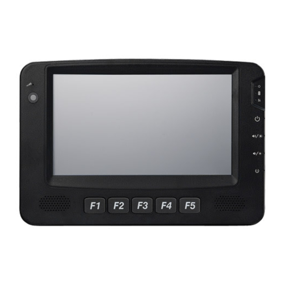
Page 24: Getting To Know Vmc 100/1000 Series
Chapter 1: Product Introduction Getting to Know VMC 100/1000 Series VMC 100/1100 Series Front & Side View Copyright © 2014 NEXCOM International Co., Ltd. All rights reserved VMC 100/1100 Series User Manual... -
Page 25: Vmc 100/1100 Series Rear View
Chapter 1: Product Introduction VMC 100/1100 Series Rear View 18 17 14 13 Note: The photo shown is VMC 1100 Copyright © 2014 NEXCOM International Co., Ltd. All rights reserved VMC 100/1100 Series User Manual... - Page 26 SIM card slot • Left Side I/O with USB client, type B connector Special Screw Lock VMC 1100 • SIM card slot • Micro SD slot Copyright © 2014 NEXCOM International Co., Ltd. All rights reserved VMC 100/1100 Series User Manual...
- Page 27 ADC 1 release KEY) A_GND DR GPS_IPPS GPI 1 DR GPS_ODO GPI 2 DR GPS_DIR VMC 100: GPI3 VMC 1100: MDI 1 (for tracker, SOS) Copyright © 2014 NEXCOM International Co., Ltd. All rights reserved VMC 100/1100 Series User Manual...
- Page 28 RJ-45 connector with RS-232 interface of either 0, 5 or 12V on pin 9 for external devices. Description 0/ 5/ 12V COM1 LAN Port The LAN port is an RJ45 interface with integrated LEDs and supports 10/100/1000Mbps Ethernet data transfer rates. Copyright © 2014 NEXCOM International Co., Ltd. All rights reserved VMC 100/1100 Series User Manual...
- Page 29 9 ~ 36VDC power input Description GND (Black line color) Power Input GND (Black line color) Connector IGNITION (Yellow line color) VIN (Red line color) VIN (Red line color) Copyright © 2014 NEXCOM International Co., Ltd. All rights reserved VMC 100/1100 Series User Manual...
-
Page 30: Chapter 2: Using The Gps Feature
WAAS/EGNOS and power saving mode. 1. Go to Device Manager to ensure the device is installed correctly. 3. Follow the given instructions to complete the installation. Copyright © 2014 NEXCOM International Co., Ltd. All rights reserved VMC 100/1100 Series User Manual... -
Page 31: Setup Window Screenshot
“VTG check box” - Some navigation or map software requires to receive VTG data output for during operation. Check the box to activate the VTG data output. Copyright © 2014 NEXCOM International Co., Ltd. All rights reserved VMC 100/1100 Series User Manual... -
Page 32: Gps Info Window Screenshot
Time (hhmmss) Blue circle indicates that is being tracked and is being used in the cur- • rent position. Copyright © 2014 NEXCOM International Co., Ltd. All rights reserved VMC 100/1100 Series User Manual... -
Page 33: Gps Information Instructions
Satellite status can be observed in the “GPS Info Window”. Use the “Tab Menu” to switch between Setup window and GPS info window. Please make sure to de-activate the GPS device before exiting this pro- gram. Copyright © 2014 NEXCOM International Co., Ltd. All rights reserved VMC 100/1100 Series User Manual... -
Page 34: Chapter 3: Jumpers And Connectors
Ground yourself before touching any internal components, by touching • Use correct screws and do not over tighten screws. a metal object. Static electricity can damage many of the electronic com- Copyright © 2014 NEXCOM International Co., Ltd. All rights reserved VMC 100/1100 Series User Manual... -
Page 35: Jumper
(on) and open (off). Two-Pin Jumpers: Open (Left) and Short (Right) Three-Pin Jumpers: Pins 1 and 2 Are Short Copyright © 2014 NEXCOM International Co., Ltd. All rights reserved VMC 100/1100 Series User Manual... -
Page 36: Locations Of The Jumpers And Connectors
Locations of the Jumpers and Connectors The figure below is the mainboard used in the VMC system. It shows the locations of the jumpers and connectors. Mainboard Copyright © 2014 NEXCOM International Co., Ltd. All rights reserved VMC 100/1100 Series User Manual... -
Page 37: Internal Connectors And Dip Switch Settings
VGA_+5V VGA_CLK VGA_DATA VGA_VS EC_KSI5 EC_KSI4 VGA_HS EC_KSI3 EC_KSI2 VGA_BLUE VGA_GREEN EC_KSI1 EC_KSI0 VGA_RED EC_KSO10 EC_KSO9 EC_KSO8 EC_KSO7 EC_KSO6 EC_KSO5 EC_KSO4 EC_KSO3 EC_KSO2 EC_KSO1 EC_KSO0 Copyright © 2014 NEXCOM International Co., Ltd. All rights reserved VMC 100/1100 Series User Manual... -
Page 38: Mcu Debug Com Header
Connector size: 1x3 3-pin header, 1.0mm pitch Connector size: 2x4 8-pin header, 1.0mm pitch Connector location: JP1 Connector location: JP2 Definition Definition Definition +V3.3ALW MCU_RST# MCU_TRST MCU_TDI MCU_TCK MCU_TMS MCU_TDO Copyright © 2014 NEXCOM International Co., Ltd. All rights reserved VMC 100/1100 Series User Manual... -
Page 39: Ec Debug Com Connector
Connector size: 1x10 10-pin header, 1.0mm pitch Connector location: J6 Connector location: J8 Definition Definition Definition PCIRST# 33M_CLK LPC_FRAME# LPC_AD3 LPC_AD2 LPC_AD1 LPC_AD0 VCC3 VCC3 Copyright © 2014 NEXCOM International Co., Ltd. All rights reserved VMC 100/1100 Series User Manual... -
Page 40: Serial-Ata
Connector size: Standard Serial ATA 7P (1.27mm, SATA-M-180) Connector size: 1x2 2-pin header, 1.25mm pitch Connector location: CN3 Connector location: J9 Definition Definition Definition SATA0_TXP SATA0_TXN VCC5 SATA0_RXN SATA0_RXP Copyright © 2014 NEXCOM International Co., Ltd. All rights reserved VMC 100/1100 Series User Manual... -
Page 41: Me/Rtc Clear Switch
Connector size: 2-pin DIP switch Connector size: 2-pin DIP switch Connector location: SW1 Connector location: SW3 Status Function Status Function Clear CMOS/ME Normal 1 OFF, 2 ON 9-36V Copyright © 2014 NEXCOM International Co., Ltd. All rights reserved VMC 100/1100 Series User Manual... -
Page 42: Gpio Pull High Switch
Boot loader or BIOS status: Blinking orange GPIO Output NC System login in status: Blinking green Power On: Solid green HDD activity: Green WWAN WWAN activity: Green Copyright © 2014 NEXCOM International Co., Ltd. All rights reserved VMC 100/1100 Series User Manual... -
Page 43: External Connectors
Connector location: CON1 Connector location: CN1 Definition Definition Definition Definition COM1-PWR RS232_RXD COM-PWR COM_RX_485TX+ RS232_TXD RS232_DTR RS-485TX- COM_TX RS232_DSR CAN1-H RS232_RTS RS232_CTS CAN1-L CAN2-H CAN2-L Copyright © 2014 NEXCOM International Co., Ltd. All rights reserved VMC 100/1100 Series User Manual... -
Page 44: Gpio And Sensor Connector
Connector size: DB-15 port, 15-pin D-Sub Connector location: CN3 Definition Definition SPEED_1 SPEED_2 A-VIN0 A-VIN1 IO_AGND G_IN-1 G_IN-2 G_IN-8 G_OUT-1 G_OUT-2 G_OUT-3 DR_GPS-1PPS DR_GPS-ODOMETER DR_GPS-DIRECTION IO_GND1 Copyright © 2014 NEXCOM International Co., Ltd. All rights reserved VMC 100/1100 Series User Manual... -
Page 45: Chapter 4: Function Key Code Constants
“How to capture a pressed function keys”, please refer to the Microsoft technical support website http://support.microsoft.com/kb/822492/en-us Key code value for ActionScript 2.0 in Adobe Flash http://help.adobe.com/en_US/AS2LCR/Flash_10.0/help.html?content=00000520.html Copyright © 2014 NEXCOM International Co., Ltd. All rights reserved VMC 100/1100 Series User Manual... -
Page 46: Extended Ascii Keyboard Codes
Chapter 4: Function Key Code Constants Extended ASCII Keyboard Codes Char. Meaning Hex Octal Binary F1 key 00111011 F2 key 00111100 F3 key 00111101 F4 key 00111110 F5 key 0011111 Copyright © 2014 NEXCOM International Co., Ltd. All rights reserved VMC 100/1100 Series User Manual... -
Page 47: Chapter 5: Touchscreen Installation Guide
The touchscreen supports the following operating systems: O.S. Linux 2000/XP/2003/VISTA/7/8 (Kernel 2.6 & X-Windows Win CE (4.2/5.0/6.0/7.0) Mode) Driver USB Driver Copyright © 2014 NEXCOM International Co., Ltd. All rights reserved VMC 100/1100 Series User Manual... -
Page 48: Install Penmount Windows Universal Driver (For 2000/Xp/Xpt/Xpe/2003/Vista/7/Wes7/2008/8)
0, 5, 10, 15, 20, 25, 30 are the default values for edge compensation. Smoothing 1. Turn on the smoothing function. 0. Turn off the smoothing function. Copyright © 2014 NEXCOM International Co., Ltd. All rights reserved VMC 100/1100 Series User Manual... - Page 49 ; TouchReport =2, it will not be installed as Digitizer mode directly in Windows 7, the user can select Digitizer or mouse mode during the installation procedure. ; COM1=PCI,38400, it will not install the driver at COM1 permanently. Copyright © 2014 NEXCOM International Co., Ltd. All rights reserved VMC 100/1100 Series User Manual...
-
Page 50: Install Penmount Mouse Driver In Windows 2000/Xp/Xpt/Xpe/2003/Vista/7/Wes7/2008/8
8. Then restart operating system. As soon as driver installation finishes, both the icons of PenMount Monitor and Gesture AP show up in the notification area. Copyright © 2014 NEXCOM International Co., Ltd. All rights reserved VMC 100/1100 Series User Manual... -
Page 51: Install Penmount Digitizer Driver In Windows Xpt/Vista/7/Wes7/2008/8
On PenMount Control Panel you are able to see the device of PenMount 6000 USB/RS-232 detected by your system under Device tab. Select a device and click the Configure button. Copyright © 2014 NEXCOM International Co., Ltd. All rights reserved VMC 100/1100 Series User Manual... -
Page 52: Penmount Control Panel
E.g. Please run ms-dos prompt or command prompt. c:\Program Files\PenMount Universal Driver\DMCCtrl.exe -calibration 4 (Standard Calibration) DMCCtrl.exe - calibration ($) 4=Standard Calibration 4 9=Advanced Calibration 9 16=Advanced Calibration 16 25=Advanced Calibration 25 Copyright © 2014 NEXCOM International Co., Ltd. All rights reserved VMC 100/1100 Series User Manual... - Page 53 NOTE: The older a touchscreen is, the more calibration points of the Advanced Mode it needs. For an optimal accuracy we suggest to use a stylus to make the advanced calibration. Copyright © 2014 NEXCOM International Co., Ltd. All rights reserved VMC 100/1100 Series User Manual...
- Page 54 Beep on both beep occurs when comes down and is lifted up. Beep Frequency modifies sound frequency. Beep Duration modifies sound duration. Copyright © 2014 NEXCOM International Co., Ltd. All rights reserved VMC 100/1100 Series User Manual...
- Page 55 Edge Compensation This page is the edge compensation settings. You can adjust the settings from 0 to 30 for accommodating the difference of each touch panel. Copyright © 2014 NEXCOM International Co., Ltd. All rights reserved VMC 100/1100 Series User Manual...
-
Page 56: Penmount Monitor Menu Icon
When you select this function, a mouse icon appears in the right-bottom of the screen. Click this icon to switch between Right and Left Button functions. Exit Exits the PenMount Monitor function. Copyright © 2014 NEXCOM International Co., Ltd. All rights reserved VMC 100/1100 Series User Manual... -
Page 57: The Touchscreen Configure Of Penmount Digitizer Driver
Configure button. The calibration screen will appear automatically. Touch this point and rotation is mapped. NOTE: Rotate function is disabled if you use Monitor Mapping. Copyright © 2014 NEXCOM International Co., Ltd. All rights reserved VMC 100/1100 Series User Manual... -
Page 58: Penmount Control Panel
25= Advanced Calibration 25 Calibrate This function offers two ways to calibrate your touchscreen. ‘Standard Calibration’ adjusts most touchscreens while ‘Advanced Calibration’ adjusts aging touchscreens. Copyright © 2014 NEXCOM International Co., Ltd. All rights reserved VMC 100/1100 Series User Manual... - Page 59 NOTE: The older a touchscreen is, the more calibration points of the Advanced Mode it needs. For an optimal accuracy we suggest to use a stylus to make the advanced calibration. Copyright © 2014 NEXCOM International Co., Ltd. All rights reserved VMC 100/1100 Series User Manual...
- Page 60 Edge Compensation This page is the edge compensation settings. You can adjust the settings from 0 to 30 for accommodating the difference of each touch panel. Copyright © 2014 NEXCOM International Co., Ltd. All rights reserved VMC 100/1100 Series User Manual...
-
Page 61: Uninstall Penmount Windows Universal Driver
5.1.8 Uninstall PenMount Windows Universal Driver 1. Go to Control Panel. Click “Add/Remove program”. Select ”PenMount Universal Driver”. Click “Change/Remove” button. 2. Select ‘Uninstall’ to remove PenMount Windows Universal Driver. Copyright © 2014 NEXCOM International Co., Ltd. All rights reserved VMC 100/1100 Series User Manual... -
Page 62: Install Penmount Linux X Window Usb Driver
Red Hat 7.3/8.0 OpenSuse 10.1/ 10.2/ 10.3/ 11/ 11.1/ 11.2/ 11.3/ 11.4/ 12.1 32_64bit Suse 10.0 Suse 9.2/9.3 Suse 8.0/9.0/9.1 Copyright © 2014 NEXCOM International Co., Ltd. All rights reserved VMC 100/1100 Series User Manual... -
Page 63: Install Penmount Wince Driver
Before installing PenMount WinCE Driver, you must have WinCE system installed and running in your device. 5.3.1 Install PenMount WinCE Driver Please see the readme file included in the driver folder. Copyright © 2014 NEXCOM International Co., Ltd. All rights reserved VMC 100/1100 Series User Manual... -
Page 64: Chapter 6: Touchscreen Driver Software Functions
Edge Compensation button or pressing the application key on Refresh the keyboard) will be supported. Copyright © 2014 NEXCOM International Co., Ltd. All rights reserved VMC 100/1100 Series User Manual... - Page 65 Enable/configure Gesture AP to support PenMount gestures recognition. Screen Rotation Monitor The function supports nVidia, Intel, SMI or ATI and software such as Portrait Pivot Pro rotation automatic detection. Copyright © 2014 NEXCOM International Co., Ltd. All rights reserved VMC 100/1100 Series User Manual...
-
Page 66: Standard Calibration
Our rotation configuration function allows you to easily match the touchscreen when you rotate your monitor. Copyright © 2014 NEXCOM International Co., Ltd. All rights reserved VMC 100/1100 Series User Manual... - Page 67 Select Clear Screen to clear drawing. Show Pen Location is to show the locations where pen comes down and lifted up on the monitor. Select Exit to quit draw function. Copyright © 2014 NEXCOM International Co., Ltd. All rights reserved VMC 100/1100 Series User Manual...
-
Page 68: Mouse Operation Mode
The drivers let the user adjust the desired touch- from appearing when using the touchscreen. The cursor appears when user screen sound, as well as turn the sound off. turns this function off. Copyright © 2014 NEXCOM International Co., Ltd. All rights reserved VMC 100/1100 Series User Manual... -
Page 69: Cursor Offset
Refresh button on PenMount Control Panel to detect the newly attached PenMount devices. (Note: Refresh is only supported by PenMount Windows Universal Driver (for Windows 2000/XP/2003/VISTA).) Copyright © 2014 NEXCOM International Co., Ltd. All rights reserved VMC 100/1100 Series User Manual... - Page 70 Chapter 6: Touchscreen Driver Software Functions Copyright © 2014 NEXCOM International Co., Ltd. All rights reserved VMC 100/1100 Series User Manual...
-
Page 71: Chapter 7: Penmount Gesture Ap For Windows
PenMount Gesture AP icon shows up in the notification area. PenMount Gesture AP is running. the notification area. See the illustration below. PenMount Gesture AP is running. PenMount Gesture AP Enabled Disabled Copyright © 2014 NEXCOM International Co., Ltd. All rights reserved VMC 100/1100 Series User Manual... -
Page 72: Configure Penmount Gesture Ap
Select Tools tab and click Gesture Setting button in PenMount Control Panel. 3. 15 PenMount Gestures are provided in total. PenMount Gestures for Windows XP Copyright © 2014 NEXCOM International Co., Ltd. All rights reserved VMC 100/1100 Series User Manual... - Page 73 Chapter 7: PenMount Gesture AP for Windows In the [Gesture Setting] window, you can proceed to configure PenMount Gesture AP: See picture below. PenMount Gestures for Windows Vista / 7/ 8 Copyright © 2014 NEXCOM International Co., Ltd. All rights reserved VMC 100/1100 Series User Manual...
-
Page 74: Penmount Gestures' Default Values In Windows Xp
(Alt + F4) to finger movement on the touch screen and the tapping will not trigger any program action. However, the gesture recognition is still functioning.) Copyright © 2014 NEXCOM International Co., Ltd. All rights reserved VMC 100/1100 Series User Manual... -
Page 75: Chapter 8: Enable A Hibernate Once/Resume Many
EWF function. Please refer to the following link. https://msdn.microsoft.com/en-US/library/ff794943(v=winembedded.60).aspx Here is all the syntax for EWF Manager (Standard 7 SP1) https://msdn.microsoft.com/en-US/library/ff794092(v=winembedded.60).aspx Copyright © 2014 NEXCOM International Co., Ltd. All rights reserved VMC 100/1100 Series User Manual... -
Page 76: How To Install The Wwan Or Wi-Fi Module
And then attach the RF cable to the module. 4. Install the rear cover. Copyright © 2014 NEXCOM International Co., Ltd. All rights reserved VMC 100/1100 Series User Manual... -
Page 77: Chapter 10: How To Install A Sata Dom Module
SATA DOM. 3. Before installing the SATA DOM, please make sure you have the following parts. SATA DOM Sponge Thermal Pad SATA Power Cable Copyright © 2014 NEXCOM International Co., Ltd. All rights reserved VMC 100/1100 Series User Manual... - Page 78 Chapter 10: How to Install a SATA DOM Module 5. Plug the SATA power cable. 6. Plug the SATA DOM to the SATA connector and then connect the SATA power cable. Copyright © 2014 NEXCOM International Co., Ltd. All rights reserved VMC 100/1100 Series User Manual...
- Page 79 Chapter 10: How to Install a SATA DOM Module 7. Paste the thermal pad on the SATA DOM board and then replace the heatsink cover. Copyright © 2014 NEXCOM International Co., Ltd. All rights reserved VMC 100/1100 Series User Manual...
-
Page 80: Chapter 11: Installing The Obd Module
4. Place the adapter board onto the OBD module, please note, the pins on the adapter board have to be inserted into the OBD module. Once fully inserted, secure the OBD module with screws. Copyright © 2014 NEXCOM International Co., Ltd. All rights reserved VMC 100/1100 Series User Manual... - Page 81 Chapter 11: Installing the OBD Module 5. Connect the cable to the module. 6. The cable passes through the hole and plugs to the connector. Top View Copyright © 2014 NEXCOM International Co., Ltd. All rights reserved VMC 100/1100 Series User Manual...
- Page 82 7. Secure the four screws to fix the module to the rear cover. 8. Place the heatsink back to its original location and secure it with screws. Copyright © 2014 NEXCOM International Co., Ltd. All rights reserved VMC 100/1100 Series User Manual...
-
Page 83: Appendix A: I/O Address Function
0: Car Battery is OK 1: Car Battery is Low voltage Bit 4: Status of +12V output 0: circuit normal(under 4A) 1: over circuit(over 4A) Copyright © 2014 NEXCOM International Co., Ltd. All rights reserved VMC 100/1100 Series User Manual... - Page 84 Bit 7 Bit 6 Bit 5 Bit 4 Bit 3 Bit 2 Bit1 Bit 0 Description 8 bits data (Bit 7 is highest bit of data) Copyright © 2014 NEXCOM International Co., Ltd. All rights reserved VMC 100/1100 Series User Manual...
- Page 85 Bit 3: status of smart battery Bit0~3: GPO0~3 0: no discharging Bit4~7: GPI0~3 1: discharging Bit 4: status of FAN R? 0: well 1: failed Copyright © 2014 NEXCOM International Co., Ltd. All rights reserved VMC 100/1100 Series User Manual...
- Page 86 Bit3: By Pass Car battery power 0: DISABLE 1: ENABLE(*) Auto clear WDT timer when read/write I/O port 0EE5H. Bit4: Wake on 3.5G MODULE 0: DISABLE(*) 1: ENABLE Copyright © 2014 NEXCOM International Co., Ltd. All rights reserved VMC 100/1100 Series User Manual...
- Page 87 30 sec 1 min 1 min 5 min 5 min 10 min 10 min 15 min 15 min 30 min 30 min 1 hour 1 hour Copyright © 2014 NEXCOM International Co., Ltd. All rights reserved VMC 100/1100 Series User Manual...
- Page 88 BIT1~0 Input Voltage 24V Startup Shutdown Startup Shutdown 11.5V 10.5V Startup Shutdown Startup Shutdown Startup Shutdown Startup Shutdown 12.5V Startup Shutdown Startup Shutdown 12.5V 11.5V Copyright © 2014 NEXCOM International Co., Ltd. All rights reserved VMC 100/1100 Series User Manual...
- Page 89 Bit0~7: the hour value (hexadecimal) 0: No data transfer 1: Data link (auto detect) I/O port: 0EEFH (User setting time) Bit0~7: the minute value (hexadecimal) Copyright © 2014 NEXCOM International Co., Ltd. All rights reserved VMC 100/1100 Series User Manual...
- Page 90 Bit 7 Bit 6 Bit 5 Bit 4 Bit 3 Bit 2 Bit1 Bit 0 Description 8 bits data (Bit 7 is highest bit of data) Copyright © 2014 NEXCOM International Co., Ltd. All rights reserved VMC 100/1100 Series User Manual...
- Page 91 1: ON Bit 3: Status of Car Battery 0: Car Battery is OK 1: Car Battery is Low voltage Bit 4: Status of +12V output Copyright © 2014 NEXCOM International Co., Ltd. All rights reserved VMC 100/1100 Series User Manual...
- Page 92 Bit 6 Bit 5 Bit 4 Bit 3 Bit 2 Bit 1 Bit 0 Description 8 bits data (Bit 7 is highest bit of data) Copyright © 2014 NEXCOM International Co., Ltd. All rights reserved VMC 100/1100 Series User Manual...
- Page 93 0: Battery capacity >= 10% 1: Battery capacity <= 10% Bit0~3: GPO0~2 Bit4~7: GPI0~2 Bit 4: Output Type 0: Use Car Battery 1: Use Backup Battery Copyright © 2014 NEXCOM International Co., Ltd. All rights reserved VMC 100/1100 Series User Manual...
- Page 94 0110 0111 0: DISABLE 1000 1: ENABLE(*) Auto clear WDT timer when read/write I/O port 0EE5H. Bit4: Wake on 3.5G MODULE 0: DISABLE(*) 1: ENABLE Copyright © 2014 NEXCOM International Co., Ltd. All rights reserved VMC 100/1100 Series User Manual...
- Page 95 1 min 1 min 5 min 5 min 10 min 10 min 30 min 15 min 1 hour 30 min 6 hour 1 hour 18 hour Copyright © 2014 NEXCOM International Co., Ltd. All rights reserved VMC 100/1100 Series User Manual...
- Page 96 BIT1~0 Input Voltage 24V Startup Shutdown Startup Shutdown 11.5V 10.5V Startup Shutdown Startup Shutdown Startup Shutdown Startup Shutdown 12.5V Startup Shutdown Startup Shutdown 12.5V 11.5V Copyright © 2014 NEXCOM International Co., Ltd. All rights reserved VMC 100/1100 Series User Manual...
- Page 97 Bit4: CANBUS Data link detect 0: No data transfer I/O port: 0EEFH (User setting time) 1: Data link (auto detect) Bit0~7: the minute value (hexadecimal) Copyright © 2014 NEXCOM International Co., Ltd. All rights reserved VMC 100/1100 Series User Manual...
- Page 98 Bit 6 Bit 5 Bit 4 Bit 3 Bit 2 Bit 1 Bit 0 Description 8 bits data (Bit 7 is highest bit of data) Copyright © 2014 NEXCOM International Co., Ltd. All rights reserved VMC 100/1100 Series User Manual...
- Page 99 0: ON (*) 1: OFF Bit4: COM2 RS485/RS422 0: COM2 RS485 (*) 1: COM2 RS422 Bit5: COM2 RS232 / RS485_RS422 0: COM2 RS232 (*) 1: COM2 RS485/RS422 Copyright © 2014 NEXCOM International Co., Ltd. All rights reserved VMC 100/1100 Series User Manual...
-
Page 100: Appendix B: Vehicle Power Management Setup
F4: Save & Exit F4: Save & Exit ESC: Exit ESC: Exit Version 2.10.1208. Copyright (C) 2010 American Megatrends, Inc. Version 2.10.1208. Copyright (C) 2010 American Megatrends, Inc. Copyright © 2014 NEXCOM International Co., Ltd. All rights reserved VMC 100/1100 Series User Manual... - Page 101 F4: Save & Exit F4: Save & Exit ESC: Exit ESC: Exit Version 2.10.1208. Copyright (C) 2010 American Megatrends, Inc. Version 2.10.1208. Copyright (C) 2010 American Megatrends, Inc. Copyright © 2014 NEXCOM International Co., Ltd. All rights reserved VMC 100/1100 Series User Manual...
- Page 102 +/-: Change Opt. F1: General Help F2: Previous Values F3: Optimized Defaults F4: Save & Exit ESC: Exit Version 2.10.1208. Copyright (C) 2010 American Megatrends, Inc. Copyright © 2014 NEXCOM International Co., Ltd. All rights reserved VMC 100/1100 Series User Manual...
- Page 103 +/-: Change Opt. F1: General Help F2: Previous Values F3: Optimized Defaults F4: Save & Exit ESC: Exit Version 2.10.1208. Copyright (C) 2010 American Megatrends, Inc. Copyright © 2014 NEXCOM International Co., Ltd. All rights reserved VMC 100/1100 Series User Manual...
- Page 104 +/-: Change Opt. F1: General Help F2: Previous Values F3: Optimized Defaults F4: Save & Exit ESC: Exit Version 2.10.1208. Copyright (C) 2010 American Megatrends, Inc. Copyright © 2014 NEXCOM International Co., Ltd. All rights reserved VMC 100/1100 Series User Manual...
- Page 105 ↑↓: Select Item 1 hour Power Off Delay Enter: Select Version 2.10.1208. Copyright (C) 2010 American Megatrends, Inc. +/-: Change Opt. F1: General Help F2: Previous Values Copyright © 2014 NEXCOM International Co., Ltd. All rights reserved VMC 100/1100 Series User Manual...
- Page 106 Power Off Delay Enter: Select Version 2.10.1208. Copyright (C) 2010 American Megatrends, Inc. Delay Off Time selection +/-: Change Opt. F1: General Help F2: Previous Values Copyright © 2014 NEXCOM International Co., Ltd. All rights reserved VMC 100/1100 Series User Manual...
-
Page 107: Appendix C: Sms And Dial Wake-Up Setting
F4: Save & Exit F4: Save & Exit ESC: Exit ESC: Exit Version 2.14.1219. Copyright (C) 2011 American Megatrends, Inc. Version 2.14.1219. Copyright (C) 2011 American Megatrends, Inc. Copyright © 2014 NEXCOM International Co., Ltd. All rights reserved VMC 100/1100 Series User Manual... -
Page 108: Appendix D: Rtc Wake-Up Setting
F4: Save & Exit F4: Save & Exit ESC: Exit ESC: Exit Version 2.14.1219. Copyright (C) 2011 American Megatrends, Inc. Version 2.14.1219. Copyright (C) 2011 American Megatrends, Inc. Copyright © 2014 NEXCOM International Co., Ltd. All rights reserved VMC 100/1100 Series User Manual... - Page 109 (5) After you have finished with the Setup, press <ESC> to go back to the main menu and then press “Enter” on “Save Changes and Reset.” Copyright © 2014 NEXCOM International Co., Ltd. All rights reserved VMC 100/1100 Series User Manual...
-
Page 110: Appendix E: Auto Backlight Setting
“Enter” on “Save Changes and Reset.” After the setup procedure is completed, the light sensors can auto-adjust a display’s backlight. Copyright © 2014 NEXCOM International Co., Ltd. All rights reserved VMC 100/1100 Series User Manual... -
Page 111: Appendix F: Bios Update
(1) Locate the “afuwin32” setup file in the “afuwin32” folder. (3) Press the “OK” button when prompted with a pop-up window. (2) Start the “afuwingui” setup program. Copyright © 2014 NEXCOM International Co., Ltd. All rights reserved VMC 100/1100 Series User Manual... - Page 112 Appendix F: BIOS Update (4) Press the “Open” button. (5) Select the BIOS file. Copyright © 2014 NEXCOM International Co., Ltd. All rights reserved VMC 100/1100 Series User Manual...
- Page 113 (6) Check all the options in “Block Options” and then press the “Flash” (7) The BIOS will be updated automatically, when the update is completed, button. please restart the VMC. Copyright © 2014 NEXCOM International Co., Ltd. All rights reserved VMC 100/1100 Series User Manual...
Need help?
Do you have a question about the VMC 100 Series and is the answer not in the manual?
Questions and answers