Sign In
Upload
Manuals
Brands
Nexcom Manuals
Automobile Accessories
VMC 4501
Nexcom VMC 4501 Vehicle Mount Computer Manuals
Manuals and User Guides for Nexcom VMC 4501 Vehicle Mount Computer. We have
1
Nexcom VMC 4501 Vehicle Mount Computer manual available for free PDF download: User Manual
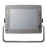
Nexcom VMC 4501 User Manual (191 pages)
Vehicle Mount Computer VMC 3000/4000 Series
Brand:
Nexcom
| Category:
Automobile Accessories
| Size: 12 MB
Table of Contents
Table of Contents
2
Acknowledgements
7
Copyright
7
Declaration of Conformity
7
Disclaimer
7
Preface
7
Regulatory Compliance Statements
7
Rohs Compliance
8
Warranty and RMA
9
Installation Recommendations
10
Safety Information
10
Safety Precautions
11
Conventions Used in this Manual
12
Technical Support and Assistance
12
Global Service Contact Information
13
Headquarters
13
Package Contents
15
Ordering Information
16
Chapter 1: Product Introduction
17
Overview
17
Key Features
17
Hardware Specifications
19
VMC 3000/3001 and VMC 4000/4001
19
VMC 3500/3501 and VMC 4500/4501
22
Mechanical Dimensions
24
VMC 3000 Series
24
VMC 4000 Series
25
Exploded View Drawing
26
Getting to Know VMC 3000
27
VMC 3000/4000 Series Front View
27
VMC 3000/4000 Series Rear View
27
VMC 3000/3500
28
VMC 3001/3501
28
VMC 4000/VMC 4500
29
VMC 4001/VMC 4501
29
External I/O Interface
32
VMC 3000/ 3500
32
CAN Bus and GPIO Connector
32
COM2 RS-232 Connector
32
COM1 RS-232 Connector
33
12V Power Output Connector
33
Power Input Connector
34
VMC 3001/ 3501
35
COM1 RS-232 Connector
35
Audio Connector
35
CAN and GPIO Connector
36
DC Input Connector
36
DC Output Connector
37
External I/O Interface
38
VMC 4000
38
RS-232/422/485 (COM2), RS-232 (COM3), CAN Bus and GPIO Connector
38
COM1 RS-232 Connector
38
12V Power Output Connector
39
Power Input Connector
39
Speaker-Out
40
MIC-In
40
VMC 4001
41
Multi I/O Connector
41
Power Input Connector
41
Audio Connector
42
CAN and GPIO Connector
42
DC Output Connector
43
LAN Connector
43
USB 2.0 Connector
44
Chapter 2: System Setup
45
System Power on
45
Power Key Functions
45
Installing a WLAN or WWAN Module
46
Installing a SATA SSD Drive
47
Installing a CAN Bus Module
49
Chapter 3: Using the GPS Feature
50
Setup and Using GPS Information
50
Setup Window Screenshot
51
GPS Info Window Screenshot
52
GPS Information Instructions
53
Chapter 4: Jumpers and Connectors for VMC 3000 Series
54
Before You Begin
54
Precautions
54
Jumper
55
Locations of the Jumpers and Connectors
56
Main Board
56
I/O Board
57
Waterproof I/O Board
57
Internal Connectors and Jumper Settings
58
Membrane Key FPC Connector
58
Port 80 Connector
58
Canbus Input Connector
59
Canbus Output Connector
59
GAL Programmer PIN Header
60
Touch Controller Connector
60
MCU Programmer Pin Header
61
Backlight Control Connector
61
MCU COM Port
62
Temp Sensor
62
Serial-ATA
63
Serial-ATA Power Input
63
Mini-Pcie Connector (3.5G)
64
Mini-Pcie Connector (WLAN)
65
SIM Card Connectors
66
Internal Connectors and Jumper Settings
67
I/O Board
67
LAN Connector
67
USB Connector
67
Speaker-Out
68
MIC-In
68
Internal Connectors and Jumper Settings
69
Waterproof I/O Board
69
Power Input Connector
69
Power Output Connector
69
LAN Connector
70
Lan Led
70
USB Connector
71
Audio Connector
71
Canbus Connector
72
COM1 Connector
72
Chapter 5: Jumpers and Connectors for VMC 4000 Series
73
Before You Begin
73
Precautions
73
Jumper
74
Locations of the Jumpers and Connectors
75
Carry Board
75
Internal Connectors and Jumper Settings for Carry Board
76
Input Voltage Select
76
Voltage Setup Selection
76
Panel Setup Selection
76
GPIO Setup Selection
77
Jumper Settings
78
CMOS Input Voltage Select
78
MCU Download
78
GAL Download
79
MCU COM Port
79
EC Download
80
EC Programmer Pin Header
80
MCU Programmer Pin Header
81
Panel Driver Board Connector
81
Serial-ATA Power Input
82
Serial-ATA
82
Usb
83
Membrane Key FPC Connector
83
Speaker Connector
84
Reset Button
84
Connector Location: SW1
84
RTC Battery Connector
85
GPS JST Connector
85
Canbus Input Connector
86
Canbus Output Connector
86
VMC 4000 I/O Board
87
RS232/485/422 Mode Selection for COM2
88
Canbus/Gps DR Mode Selection
89
COM1 Ri/Power Switch
90
VGA Connector
90
Canbus Input Connector
91
Canbus Output Connector
91
USB Connector
92
VMC 4001 Waterproof I/O Board
93
GPIO1.2/CAN2 Mode Selection
94
RS232/RS485/RS422 Mode Selection for COM2
95
COM1 Ri/Power Switch
96
Power Input Connector
96
Power Output Connector
97
USB Connector
97
USB Connector
98
Audio Connector
98
LAN1 Connector
99
LAN2 Connector
100
LAN LED Connector
101
Canbus/Gpio Connector
101
Canbus Input Connector
102
Canbus Output Connector
102
VGA Connector
103
COM Connector
103
Chapter 6: Function Key Code Constants
104
Visual Basic Reference
104
Extended ASCII Keyboard Codes
105
Chapter 7: Touchscreen Installation Guide
106
Install Penmount Windows Universal Driver (for 2000/XP/XPT/XPE/2003/VISTA/7/WES7/2008/8)
107
Install Penmount Mouse Driver in Windows 2000/XP/XPT/XPE/2003/VISTA/7/WES7/2008/8
109
Install Penmount Digitizer Driver in Windows XPT/VISTA/7/WES7/2008/8
110
Configure Touchscreen in Penmount Mouse Driver
110
Penmount Control Panel
111
Penmount Monitor Menu Icon
115
Penmount Rotating Function
115
The Touchscreen Configure of Penmount Digitizer Driver
116
Penmount Control Panel
117
Uninstall Penmount Windows Universal Driver
120
Install Penmount Linux X Window USB Driver
121
Calibration Utilities
121
Install Penmount Wince Driver
122
Chapter 8: Touchscreen Driver Software Functions
123
Standard Calibration
125
Advanced Calibration
125
Rotation
125
Draw
125
Mouse Operation Mode
127
Beep Sound
127
Beep Sound Adjustable
127
Wake up Function
127
Plot Calibration Data
127
Right Button
127
Hide Cursor
127
Cursor Offset
128
Double Click Area and Speed
128
About
128
Edge Compensation
128
Refresh
128
Chapter 9: Penmount Gesture AP for Windows
130
Invoke Penmount Gesture AP
130
Configure Penmount Gesture AP
131
Penmount Gestures' Default Values in Windows XP
133
Chapter 10: Hotkey Setup Procedure
134
Installing NEXCOM Function Key App
134
Applying Administrator Authority
136
Setup Hotkey Function
137
Setup Hotkey Function - User Define
138
How to Switch Hotkey Button
139
Appendix A: I/O Address Function
140
VMC 3000 Series
140
VMC 4000 Series
148
Appendix B: Vehicle Power Management Setup
157
Vehicle Power Management Setup
158
Appendix C: Power Consumption
164
Appendix D: SMS and Dial Wake-Up Setting
166
Appendix E: RTC Wake-Up Setting
167
Appendix F: Auto Backlight Setting
169
Appendix G: BIOS Update
170
Appendix H: CAN Module Setup and Command
173
Appendix I
191
Setting up Power Cable for Ignition Function
191
Advertisement
Advertisement
Related Products
Nexcom VMC 4000
Nexcom VMC 4500
Nexcom VMC 4001
Nexcom VMC 3020
Nexcom VMC 3000
Nexcom VMC 3500
Nexcom VMC 3501
Nexcom VMC 1100
Nexcom VMC 1000
Nexcom VMC 100 Series
Nexcom Categories
Motherboard
Desktop
Industrial PC
Network Hardware
Digital Signage
More Nexcom Manuals
Login
Sign In
OR
Sign in with Facebook
Sign in with Google
Upload manual
Upload from disk
Upload from URL