Table of Contents
Advertisement
Quick Links
Advertisement
Table of Contents

Related Manuals for Digital Alert Systems DASDEC II


Summary of Contents for Digital Alert Systems DASDEC II
-
Page 1: User Manual
DASDEC II Digital/Analog Emergency Alert System Encoder/Decoder User Manual Model DASDEC-1EN Version 2.6-0 March 27, 2015 Digital Alert Systems A Division of Monroe Electronics Inc. 100 Housel Ave Lyndonville, NY 14098 www.digitalalertsystems.com... - Page 2 Digital Alert Systems A Division of Monroe Electronics Inc. All Rights Reserved DASDEC is a Trademark of Digital Alert Systems Chyron CODI is a Trademark of Chyron Corporation. NDU is a Trademark of Vela Inc. Cable Envoy and CEMS are Trademarks of Monroe Electronics VDS-840 is a Trademark of Keywest Technology.
-
Page 3: Table Of Contents
Table of Contents INTRODUCTION TO THE DASDEC II and the USER MANUAL ............... 1 The Formatting of this Manual ......................... 2 Organization of Manual for Setting up your DASDEC II ................2 Conventions used in this Manual (Symbols, Links, Screenshots, Notes) ..........2 ... - Page 4 CPU ..............................145 7.2.6 PCI ..............................145 7.2.7 IO ..............................145 Server > Logs: Server Logs ...................... 145 7.3.1 Web Session Log: DASDEC II Emergency Alert System Encoder/Decoder Platform ......145 7.3.2 Operation Log ..........................145...
- Page 5 Backing up the DASDEC configuration file ..................154 Uploading an audio file in a DASDEC ....................155 Appendix ..............................156 DASDEC II Hardware and Software Specifications ................156 An Emergency Alert System Analog/Digital Encoder/Decoder Platform ............156 Hardware Specs ...............................156 ...
-
Page 7: Introduction To The Dasdec Ii And The User Manual
PDF and HTML formats. New features continue to be added to the DASDEC II platform. This manual is updated either in entirety, or by addendum, as new features become available. Your comments! Your comments on the usefulness of the manual, or suggestions for improvement, are welcome. Please let us know how we can serve you better. -
Page 8: The Formatting Of This Manual
A screen shot is an image to show the visible items on the monitor when certain DASDEC II selections are made or activity is ongoing. The image demonstrates a feature or particular setup. A screen shot is generally the result of following the instructions in the manual for a particular task. -
Page 9: App-Notes To Help You Configure Your Dasdec
DASDEC™ Postscript Printer Setup using "printconf" Alert Forwarding over IP with EAS-Net™ PuTTY SSH Client on Windows® to remote DASDEC DASDEC™ Digital Audio Insertion with BDI AES-302 Multichannel Crawls and Digital Audio/Switching for DASDEC™ with MultiStation™ Option Digital Alert Systems: DASDEC User Manual... -
Page 10: Dasdec Ii Hardware
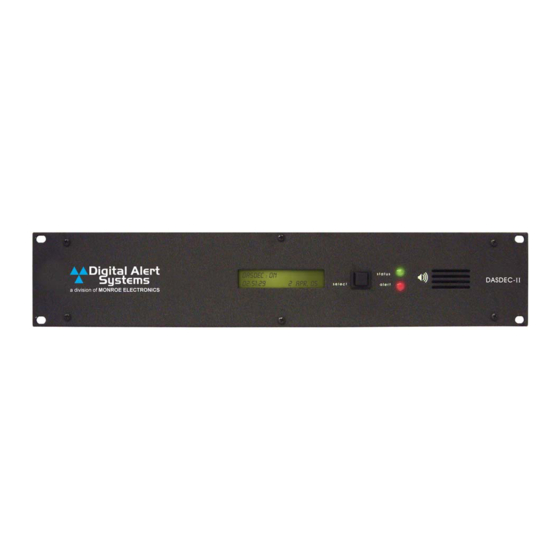
Introduction The DASDEC II is a 2U rack mounted unit built with the latest digital PC computer technology. It is an embedded PC platform. The front of the DASDEC II, pictured below, provides a very simple face for a very sophisticated platform. The DASDEC II exposes the PC motherboard connectors and single PCI slot in the rear of the unit. -
Page 11: Status Led
1.2.2 Status LED The DASDEC II's two LEDS are used for a variety of status indications, making it easy to see the state of certain important system information. System Status - Green LED When the DASDEC II is first powered on, the green LED is dark. -
Page 12: Setup: Hardware
2 Setup: Hardware Audio Wiring Audio wiring on the DASDEC II has some flexibility due to the option of adding a second sound card and because of built- in software control. Here are a few rules: EAS decoder input uses the analog audio line inputs or internal radio receivers. -
Page 13: Video Wiring
Video Wiring Video output from the DASDEC II is an optional feature. When enabled, an NTSC analog composite video signal is available from the RCA jack. This will provide a full details page during alert forwarding and/or alert origination. The video page display takes a few moments to initialize. -
Page 14: Optional Expansion Gpio
Serial Port Wiring The DASDEC II is equipped with one RS232 serial port on the back panel. In addition, one USB connection can be used with a USB/serial port expander to provide up to four (4) more RS232 serial ports. The USB port expander requires an FDTI chipset for compatibility. -
Page 15: Mpeg Encoder Card Wiring
Encoder card. Likewise, one audio output needs to be cabled to the MPEG audio input port. Optional MPEG2 PCI Encoder Card Audio/Video connections Digital Alert Systems: DASDEC User Manual... -
Page 16: Dascec Ii Server Interface
NOTE: the DASDEC II must be fully booted before it can provide a network connection. Once the DASDEC II is correctly wired; power up by pressing the power switch or rocker on the upper left corner of the backside. The LCD screen will light up if power is applied. Allow the DASDEC II time to boot. The LCD screen and the green system status LED will indicate when the DASDEC II is ready. -
Page 17: Lan Connection With A Networked Host Computer
DASDEC II Web Browser Login Screen To reach the DASDEC II Web interface from a browser, make sure the DASDEC II is on the same LAN as the browser host and type http://<DASDEC II IP Address> (for example, http://192.168.0.200). If secure access has been configured, you must use https and a browser that supports 128-bit SSL encryption. -
Page 18: Dasdec Ii Page Organization, Web Interface And Navigation
Page Title (Page Name). Software Version. The DASDEC II software version number is located in the box on the top right side of the page. The software version indicator provides a quick hyperlink to the Server Help page (Chapter 7.1 Server >... -
Page 19: Web Interface And Navigation
Commands can be entered with a mouse or the keyboard. The DASDEC II has three navigation levels. The first level is one of the three or four tabbed menus at the top of the header: Encoder, Decoder, Server, or Setup. - Page 20 The page updates immediately. (In this manual, the instructions for text entry fields say, "Click page to change and update.") Some browsers also accept text entry changes when you press the Enter key on your keyboard. 14 Digital Alert Systems: DASDEC User Manual...
-
Page 21: Setup: Web Interface
"radio buttons'. Only one radio button can be selected at a time. In left to right order the buttons are: At the first login, before the DASDEC II can be used, the server must be set up and pre-configured. The recommended order is to first set up the Server, then Network, Time, Users, Email, Audio, Video/CG, Decoder, Encoder, Net Alerts, GPIO, Printer and Alert Storage. - Page 22 The Server Network Security Configuration page has a section Web Interface Access Security where you can modify the Access security checkbox. If this box is checked, web access to the DASDEC II will be forced to be in 128 bit SSL secured https. Use this if the DASDEC II is ever on a public LAN. Left unchecked, the access allows both http and https.
- Page 23 Verify the license key configuration and make changes if needed. Submit changes to license keys using the button. See NOTE before concerning use of the button. Setup > Server > Main/License Web Page, License Key Configuration Digital Alert Systems: DASDEC User Manual...
- Page 24 When the Master key is valid, you can configure the DASDEC II decoder. Without a valid Master key, you can only configure a subset of the basic DASDEC II features. This includes the network, a new server name, and security features, like the Web interface login password and forced https access.
- Page 25 Nexgen (provider of scheduling and broadcast software for radio, Internet and television stations). DVS168 Single Client The DASDEC II presents this option as a stand-alone licensed feature if the EAS NET protocol is not licensed. It unlocks EAS alert network forwarding via the original SCTE DVS168/EARS specifications to a single DVS168 server.
-
Page 26: Configuration Management: Server Configuration Management
They provide a way to restore your DASDEC II settings in case of catastrophic disk failure, or in the case of an upgrade error, or to restore the state of former DASDEC II settings when experimenting with new settings. - Page 27 Server Configuration File Management with Backup Files The screen shot of this page shows a DASDEC II with both a current and previous backup configuration files. There are three main areas to review on the Server Configuration File Management page: Previous Configuration, Configuration Backup Files, and Upload DASDEC II Configuration File.
-
Page 28: Upgrade: Server Software Upgrade
Once uploaded, the file appears in the configuration backup file list. Then it can be managed as described above (renamed, installed, deleted, etc.). Type in full path of DASDEC II Config Backup file on your host computer, or use Browse to find DASDEC II Config Backup file. Click . - Page 29 A confirmation page allows you to continue with or cancel the upgrade. After accepting the upgrade, an error status is returned about the file if it is not an acceptable DASDEC II upgrade file. Otherwise, you will be logged off the DASDEC II Web interface and will be directed to log back in after a short waiting period. The upgrade should only take about a minute to complete.
-
Page 30: Options
/etc/hosts file. The DASDEC II server can be configured to have static IP addresses or can use DHCP to automatically assign network addresses. A second network interface can also be configured with a static or DHCP address. The second network interface will only be enabled if the correct hardware is installed. - Page 31 The primary network interface on the DASDEC II defaults to a static IP address of 192.168.0.200. This is a commonly used, non-public IP address for LAN based appliance hardware. This value is meant to be changed. The default IP netmask is 255.255.0.0. No default DNS or gateway is configured. If the gateway is selected, it defaults to 192.168.0.1.
- Page 32 Network Interface. A gateway is needed if the DASDEC II is to have direct access to the internet or to other networks within a LAN, or if the DASDEC II will be multicast streaming either MPEG Audio/Video or SCTE-18. If a gateway is required, either network interface can determine the gateway address range;...
- Page 33 You must be CAREFUL when configuring a static network address if you are configuring from a remote host. If an address which is inaccessible to your network is accepted for the DASDEC II, you will not be able to log back in from the remote host. Second network interface option The Second Network Interface checkbox below the main Network configuration box controls use of an optional second network interface.
- Page 34 These are 10.0.0.0 and 192.168.0.0. If the DASDEC II will be configured to run on a similar network, for example 10.100.1.0, it is very likely that the default static-route of 10.0.0.0 should be disabled or deleted.
-
Page 35: Security: Server Network Security Configuration
DASDEC II's public/private key pair must be "authorized" on the remote platform. Authorization usually is achieved by copying the public key into a file on the remote host. The DASDEC II uses the open source package OpenSSH for SSH features. This package has a file called "authorized_keys2" under /root/.ssh/ to hold the authorized public keys from remote platforms. - Page 36 Select a test and click the button to see the test results. Be patient; it can take several seconds to run some of these tests. Results are printed just below the button. 30 Digital Alert Systems: DASDEC User Manual...
-
Page 37: Proxy
CAP data acquisition via HTTP/HTTPS. Setup > Time: Server Date and Time Configuration The Setup Time page allows the hardware clock on the DASDEC II to be set. Date, time, and time zone may be set. Setup > Time: web page... -
Page 38: Setup > Users
Make changes to date and/or time and/or time zone, and then click Submit Date/Time/ Time zone Changes. If time zone is changed, the DASDEC II will restart, and you will be forced to log back into the Web interface. If the time is set forward far enough, you will also be forced to log back into the DASDEC II Web interface. - Page 39 Setup > Users web page The DASDEC II allows multiple active user sessions. The same user or different users can be logged in more than once and at the same time. A count of the number of active sessions is provided in the page header display on the right side of the User:'accountname' text display.
- Page 40 For instance, only a user with Administration permission may access the Setup Users page. Trying to access a DASDEC II page without the proper permission level will display a message explaining the required permission level. See chart below.
-
Page 41: Setup > Email
C. No alerts can be originated. No manual forwarding. Setup > Email The DASDEC II can be configured to optionally send email upon alert decoding, origination, and forwarding. Select the Setup > Email page to configure an outgoing email server and to configure the send options. There are four tabbed sections: Email Server, Event Email, Decoder Email, and Encoder Email. -
Page 42: Event Email
4.5.2 Event Email This page allows the user to the ability to have Event logs emailed either weekly or monthly, and to be emailed when a successfully or failed login to the DASDEC II has occurred. Emailing EAS Event Reports Check either of the boxes to disable or enable Emailing of Event Reports either on a monthly or weekly basis. -
Page 43: Decoder Email
Setup > Email > Event Email 4.5.3 Decoder Email To set up the outgoing email for the DASDEC II decoder events, select Setup Email > Decoder Email. Email can be sent upon alert decoding and/or forwarding. The Email Server is identified. If changes to the outgoing email server are needed, return to the Setup Email >Email Server screen. -
Page 44: Encoder Email
Click Accept Changes. 4.5.4 Encoder Email To setup the outgoing email for the DASDEC II encoder events, select Setup Email > Encoder Email. Email can be sent upon alert origination. Follow screen instructions or the same method described above for Decoder Email. -
Page 45: Audio Output Levels/Tests: Direct Audio Output Levels And Tests
NOTE: Setup Audio web interface pages for Decoder and Encoder Audio display and reference audio output levels for certain features. These references always provide an active hyperlink into this page to allow for changes to audio output levels. Digital Alert Systems: DASDEC User Manual... - Page 46 NOTE: This same control is presented under Setup > Decoder Audio > Alert Forwarding Audio Configuration and under Setup > Encoder Audio > Alert Encoder Audio Configuration. The sample rate applies to audio for both alert Forwarding and Origination. Audio Preview Devices 40 Digital Alert Systems: DASDEC User Manual...
- Page 47 Forwarding/Encoder Output Enable - Both Alert Forwarding and Origination audio are always enabled (played) on the Front Panel Speaker. There is no link to edit in this section for the Front Panel Speaker. Setup > Audio > Audio Output Levels/Tests web page, middle section Digital Alert Systems: DASDEC User Manual...
-
Page 48: Radio Tuners
Radio Configuration page. Each radio can be programmed to any AM, FM, or NOAA frequency. NOTE: External antennas are usually required for proper radio reception. Antennas are connected to a coax connector on the back of the DASDEC II. Antennas can be purchased through third party vendors. For recommendations, contact Digital Alert Systems. - Page 49 (displayed per decoder under the Setup Audio > Decoder Audio page). NOTE: It is important to tune the radios to stations that carry EAS alerts. This is a fundamental part of setting up your DASDEC II for monitoring the Emergency Alert System.
-
Page 50: Decoder Audio: Alert Decoding Audio Configuration
The standard DASDEC has three built-in radio receivers. Two are connected to the main audio device. The third is connected through the Audio Input Source "Internal A" connection. A fourth audio source, from the back panel screw connector terminal, is also routed through this input channel. 44 Digital Alert Systems: DASDEC User Manual... - Page 51 This feature allows detailed troubleshooting in the case where incoming EAS audio has resulted in decoder errors. Careful analysis of the post-alert snapshot audio can pinpoint the nature and source of upstream EAS errors. Digital Alert Systems: DASDEC User Manual...
- Page 52 The Select Decoder Audio to Monitor list presents all of the decoder audio channels available to hear. The Decoder Audio Monitor Output list allows a specific output port to be selected to hear the audio chosen in Select Decoder Audio to Monitor. 46 Digital Alert Systems: DASDEC User Manual...
- Page 53 Encoder Audio Configuration and under Setup > Audio Output Levels/Tests. The sample rate applies to audio for both alert Forwarding and Origination. NOTE 2: AES Audio output requires 32000 or more samples per second. Digital Alert Systems: DASDEC User Manual...
- Page 54 DAS customer support. In very rare cases, restarting the sound system can solve unusual audio problems. The AES digital audio option requires ALSA. 48 Digital Alert Systems: DASDEC User Manual...
- Page 55 Alert Decoder configuration section for Setup > Audio > Decoder Audio: bottom half of web page Digital Alert Systems: DASDEC User Manual...
-
Page 56: Encoder Audio
EAS Audio play-out relay is closed. NOTE: This same control is presented under Setup > Encoder Audio > Alert Encoder Audio Configuration. The delay time applies to both alert Forwarding and Origination. 50 Digital Alert Systems: DASDEC User Manual... - Page 57 0 - 100 in the Record Input Level field. After you set the value, you must click on the text "(click here to activate changed value)". NOTE: During recording, the DECODERS on the selected audio card source are DISABLED! Digital Alert Systems: DASDEC User Manual...
- Page 58 Setup > Audio > Encoder Audio 52 Digital Alert Systems: DASDEC User Manual...
-
Page 59: Setup Video/Cg > Video/Character Generator Configuration
In Broadcast mode, there are six tabbed sub-pages on the Setup Main Serial CG Options page: Video Out, Main Serial and USB Serial 1 through 4 for up to four expansion USB serial ports. Broadcast mode DASDEC II's support up to five (5) simultaneous serial ports (one main RS232 port on the back panel, and 1 to 4 expansion RS232 ports provided via a USB port expander), each running a different character generator protocol. -
Page 60: Usb Serial 1 Through 4
These ports are supported using the Serial Gear CS-42042 USB to 4 Port RS232 Adapter. Other adapters may work, but they must be based on the FTDI chipset. As with the Main Serial Port, make sure that the proper cable 54 Digital Alert Systems: DASDEC User Manual... - Page 61 NOT available on the USB serial ports. The TFT standard protocol is available, but only one instance of the protocol will actually be allowed to control audio play-out on the DASDEC II. The first instance configured on Main or USB ports 1-4 would be granted the privilege of running audio.
-
Page 62: Serial Port Protocols
If the port is unavailable (the USB expansion unit is not installed) on the DASDEC II, it would read: Expansion USB Serial 1 Not Available! The screen shot shows an example of the USB 1 serial port with the BetaBrite LED protocol enabled. The FIPS and EAS code filter interface operates just like the same interface on the Main Serial port configuration page. - Page 63 FIPS and EAS filtered alerts is sent to the remote device using the Sage News Room protocol. Serial Port Baud Rate – Defaults to 9600. Select 9600 or 19200 baud depending on the remote device Digital Alert Systems: DASDEC User Manual...
- Page 64 Set Alert Video Repetition Period field. The repeat period has to be at least 2 minutes. XBOB4 CG Vertical Line position – Defaults to one. Sets the vertical location of the crawl on the screen from 0 (topmost) to 16 (bottom) 58 Digital Alert Systems: DASDEC User Manual...
-
Page 65: Video Out
Video Output upon Alert Origination/Forwarding. Use the checkbox to Enable or Disable the base station Video Output If licensed and the hardware support is enabled; a DASDEC II can provide a full screen NTSC analog video display of the current originated or forwarded alert. -
Page 66: Setup > Decoder: Setup Decoder Forwarding Options
Setup > Decoder: Setup Decoder Forwarding Options A standard DASDEC II will run two EAS decoder channels from the Main audio device and two from the Auxiliary Audio device. It will decode EAS out of the box, once the Master license key is valid. However, a variety of useful options can be configured to tune the decoder for operation in a specific system within a specific geographic region. -
Page 67: Forwarding: Decoder Forwarding Configuration
Demo Decode/Forwarding and Other. A Decoder only DASDEC II will present a fifth tabbed page, Required Tests. This page requires a FIPS location code for the geographical location of the DASDEC II. The location code will be used for the One-Button Weekly Test. The interface also supports configuring random Weekly Test generation. - Page 68 Use EAS NET originating unit station ID when forwarding an EAS NET received alert. Forwarding EAS Station ID Type up to 8 characters in this text field to identify the Station ID for this DASDEC II. This code will be included in all forwarded alerts, both manually forwarded and automatically forwarded alerts.
- Page 69 Auto-Forward Mode is Enabled or Disabled and which mode is currently selected. When Manual forwarding is set, a user of the DASDEC II must use the Web Interface or use GPI input contact closures to actively forward any unforwarded alerts from the Decoder > Incoming/Decoded Alerts Active Decoded list display.
- Page 70 For both timers, the start time and the stop time fields need to be modified by the system administrator to configure when the DASDEC II will go into Auto- Forward mode and it will go back to Manual mode. In the screen shot above, Auto-Forward Mode is active from 11PM to Noon on Weekdays and all day on Saturday and Sunday.
- Page 71 Monthly test for the same FIPS codes, and with the same start time and duration, but the stations have changed the station ID. The alerts arrive several minutes apart. The DASDEC II has been set to auto-forward Monthly tests to the given FIPS codes. The first decoded Monthly test is forwarded automatically.
- Page 72 Configure FIPS code filters for Decoder Auto-Forwarding The FIPS configuration section is to set the location code for the DASDEC II. A FIPS code is a unique 6 digit code that covers every State or Territory in the United States, as well as every County or County Equivalent area in the U.S.
- Page 73 The base station configuration is simply the sum total of the DASDEC II options that enable system wide control over video character generators (CGs), GPIO relay outputs, audio output ports, and network alert connections.
- Page 74 In both cases simultaneous alert broadcast must occur on the entire set of DASDEC II controlled stations. Make sure the DASDEC II will correctly broadcast an EAS to ALL stations with a single alert broadcast while in multistation mode.
- Page 75 EAS alerts sequentially to any one of the set of collocated stations (or broadcast channels). During setup, this is achieved by choosing an exact subset of the base station DASDEC II hardware connections for each individual station (or channel). The choices are made within a station configuration interface on the Setup >...
- Page 76 You can rename the interface using the Station Configuration Interface Name text field. This changes the label displayed for the station in the pull-down menu Select Station Configuration Interface. The name also appears in many other places on the DASDEC II user interface where station references are made.
-
Page 77: Local Access Forwarding
CEM alert is auto-forwarded after being decoded from specific decoder channels and optionally, from a specific EAS source station (as based on decoded station ID). The mode is enabled using the checkbox Custom Text Translation for CEM (Civil Emergency Message). Digital Alert Systems: DASDEC User Manual... - Page 78 When a CEM alert is forwarded under control of Local Access Forwarding, the status window will display the DASDEC II ID of the local access message, information about the repetition number of the play-out and when it will stop. It also provides a large flashing button for manually stopping the alert play-out at any time. While the message play-out is active, the Setup >...
- Page 79 "Last night's snow storm has closed city offices today'. When a decoded CEM alert is forwarded, this text will be displayed on the DASDEC II video details page, and will be sent to any serially connected character generators and network protocols.
-
Page 80: Custom Msg Forwarding
This option gives the DASDEC the ability to auto forward decoded EAS NET custom messages, even if the DASDEC is in manual forwarding mode. Setup > Decoder > Custom MSG Forwarding: Options enabled 74 Digital Alert Systems: DASDEC User Manual... -
Page 81: Demo Decode/Forwarding
DASDEC II. The actual alert is generated with a button named Run Demo Decoded Alert on the Decoder > Incoming/Decoded Alerts page. (See Chapter 6.2 Incoming/Decoded Alerts). Once generated, all of the forwarding buttons and edit/review options for the active alert are available for operation. -
Page 82: Other: Setup Decoder Option Links
Setup > Encoder To run EAS encoding, a DASDEC II must first be configured with a valid Encoder license key. Verify or enter the license key on the Setup > Server page. See Chapter 4.1.1 Main/License: Server Name & License Key Configuration. Without a valid license key, the DASDEC II will not show a Setup >... - Page 83 Custom Origination (ORG) Code Translation. In the screen shot, the phrase, "The Digital Alert Systems DASDEC II,” has been entered as the custom text. Thus EAS translation text will use this phrase instead of the generic "A Broadcast or Cable System"; the phrase `HAS ISSUED` follows the custom organization name in the alert translation.
- Page 84 EAS Station ID Type up to 8 characters in this text field to identify the Station ID for this DASDEC II. This code is included in all originated alerts, both manually forwarded and automatically forwarded alerts. NOTE: Encoder Station ID can be programmed differently from Forwarding Station ID, although usually they should be the same value.
- Page 85 Just as for the available EAS Codes list, a commonly used list of FIPS locations are to be constructed from the list of all possible FIPS. The list is referred to on the DASDEC II as the "Available Encoder FIPS Locations".
- Page 86 Setup > Encoder > General page showing Base Station options The screen shot above shows the Setup > Encoder > General page when Multistation mode is licensed and when the base station configuration interface has been chosen. 80 Digital Alert Systems: DASDEC User Manual...
- Page 87 You can rename the interface using the Station Configuration Interface Name text field. This option changes the label displayed for the station in the pull-down menu Select Station Configuration Interface. The name also appears in many other places on the DASDEC II user interface where station references are made.
-
Page 88: Required Tests
The Setup Encoder > Required Tests sub-page is used to configure the DASDEC II for issuing pre-configured Weekly Test alerts. Once configured, this feature allows the DASDEC II to send a Required Weekly test with a single button push (from the Encoder > Send EAS > One-Button EAS page and from the Front Panel button) or at a random time once a week. - Page 89 If changes are made, a previously scheduled weekly test must be manually cancelled before a new test will be scheduled within the new time frame. See Encoder > Originated Alerts. Setup > Encoder > Required Tests Configure One-Button and Automatic Weekly Test. Digital Alert Systems: DASDEC User Manual...
-
Page 90: Other
Random Weekly Tests (RWT) remains scheduled regardless of other alerts that air. Check to enable. Front Panel Button Weekly Test This checkbox controls whether the DASDEC II Front Panel button is enabled or disabled for issuing a Weekly Test alert. Defaults to Enabled. Uncheck to Disable. -
Page 91: Setup > Net Alerts: Setup Network Alert Protocol Options
One of the benefits of the DASDEC II's inherent network nature is that it can support a variety of methods for network forwarding/origination of EAS alerts, alert audio/video, and remote control. The DASDEC II supports several network protocols. - Page 92 If any of these EAS are included in the incoming forwarded alert, the alert will be sent to the DVS-168 client. Setup > Net Alerts > DVS168 86 Digital Alert Systems: DASDEC User Manual...
-
Page 93: Eas Net
EAS NET operates by sending optional audio, optional text translations, and an EAS event notification file from a DASDEC II to a remote device over a LAN or WAN. There are some differences depending upon the chosen EAS NET protocol. SSH STDIN Only does not offer sending of digital audio WAV files or text translations. - Page 94 This is used primarily to provide live EAN/EAT audio from EAS NET send to an EAS NET client device (including another DASDEC II). The stream is not an MPEG transport stream. It is an http audio stream. Remote clients must actively load the URL for the stream in order to play it.
- Page 95 DASDEC II EAS NET decoder. The default is to not stream the header or EOM sequence, just the audio voice message. Use the options as required by the specific application on a remote server.
- Page 96 EAS NET event. All EAS NET protocols will send an alert event data notification file or ASCII data string from the DASDEC II to the EAS NET remote server host.
- Page 97 Use the provided checkbox to enable a non-passive connection if needed. TCP event notification – Uses a TCP socket from the DASDEC II to the remote host to send the alert event file. For sending the optional data files, one of FTP or SSH SCP network protocols can be selected.
- Page 98 NET prior send is only needed with EAS NET compatible equipment that depends upon GPI controlled delayed alert play-out. SSH Public Encryption Key link. The SSH based protocols provide this link to the display of the DASDEC II public key. This must be copied to remote host's authorization file. Composite Audio File Send When enabled (checked) a composite WAV file of the entire EAS audio track will be sent as a separate file to the EAS NET client's remote host.
- Page 99 EAS FIPS codes, the alert will be sent using the EAS NET client. With careful use of this feature, and with multiple clients, one DASDEC II can serve many different cable regions at the same time.
- Page 100 Setup > Net Alerts > EAS NET Client Configuration - DVS168/EARS 94 Digital Alert Systems: DASDEC User Manual...
-
Page 101: Cap Decode
DVS168/EARS operation - When a forwarded/originated EAS alert is to be sent using a DVS-168 EAS NET client, a TCP socket is temporarily opened from the DASDEC II to the DVS-168 remote host. If this succeeds, and the alert is a non-national alert (and FTP is enabled), a WAV file of the EAS audio and a text file of the alert details are FTP'ed to the DVS-168 remote server host. - Page 102 URL path and other options under advanced option setup. Under each of those polling options are very similar credentials that need to be filled out in order to connect 96 Digital Alert Systems: DASDEC User Manual...
- Page 103 CAP Alerts for your county, and your entire state (Not every specific county in the state, but the option that gives you the entire state FIPS code). Setup > Net Alerts > CAP Decode; FIPS Codes Digital Alert Systems: DASDEC User Manual...
- Page 104 URL path Enter your county and your state in your FIPS list (And maybe some surrounding counties) Setup > Net Alerts > CAP Decode; Quick connect to FEMA CAP Server 98 Digital Alert Systems: DASDEC User Manual...
-
Page 105: Dvs644 (Scte18)
As stated above, this feature requires the DVS644/SCTE18 license. WhenDVS644/SCTE18 support is available on the DASDEC II, the tabbed sub-page for this feature appears under Setup > Net Alerts. Two toggles are displayed for enabling DVS644/SCTE18 during alert forwarding and origination. - Page 106 Use the ENABLE Client Interface toggle box to enable/disable a client interface at any time. Each client can be independently enabled and disabled allowing an easy way to stop or restart using a client for a specific region. 100 Digital Alert Systems: DASDEC User Manual...
- Page 107 If Advanced DSG delivery is used then the a text field option is displayed for setting the Network MTU (Max transmission unit) is available. This defaults to 1500 but can be set lower if needed based on a specific network. Digital Alert Systems: DASDEC User Manual...
- Page 108 NDS Tune Private Descriptor - Check to enable the NDS Tune Private Descriptor method. This is a special private descriptor for synching a DASDEC II to an NDS system. Use of this method requires custom support by the DVS644/SCTE18 message processor.
- Page 109 II supports this reset mode by allowing an alert to be set to 0 priority. This setting should only be used for one alert, and then changed to 1-15. There is also a field to extend the alert duration past the default DASDEC II audio duration.
-
Page 110: Stream Mpeg
EAS codes from the provided lists and add to the client EAS list. If the EAS codes of an active forwarded/originated alert matches any of these EAS, the alert will be sent using the DVS-644/SCTE18 client. With careful use of this feature, and with multiple clients, one DASDEC II can serve many different cable regions at the same time. - Page 111 The Multicast TTL value must be set high enough to insure the multicast data is sent past all the LAN routers between the One-Net and the destinations. Also, as with the EAS NET and DVS644 interfaces, FIPS and EAS code based triggering is supported per client. Digital Alert Systems: DASDEC User Manual...
-
Page 112: Net Cg
This page allows configuration of up to five client targets for running alert crawls. The Net CG units must support Ethernet and be connected to the same LAN as the DASDEC II. As in the other Net Alert pages, use the Alert Forwarding and/or the Encoder Originated Alert toggles to enable/disable the use of Net CG clients when alerts are forwarded and/or originated. - Page 113 Select client: Use the pull-down menu to select the client interface to examine or configure. [ ] Listen for Net GPIO Input. When Enabled this checkbox causes the DASDEC II server to listen for input contact closures from the Net GPIO units. This option only works if at least one of the connected Online Net GPIO units supports inputs.
- Page 114 Model - Select from one of the three supported models from the pull down menu. Make sure the model fits the intended target. Password - If the Net GPIO unit supports a password and is configured to require a password, enter the password here. 108 Digital Alert Systems: DASDEC User Manual...
- Page 115 NET GPIO Output Relay Trigger Options NET GPIO Output Relay selectors: Each client provides up to 4 relays. A variety of DASDEC II alert states can be used to trigger a relay. The screen shot below shows the various triggering actions.
-
Page 116: Setup > Gpio: Setup General Purpose Io Options
The Setup GPIO page displays the state of the General Purpose Inputs and Outputs (GPIO) and allows programming. GPIO is provided by connectors on the back panel of the DASDEC II. The state of the Front Panel button is included in the GPIO table display. - Page 117 Choose the FIPS and EAS codes that will control which alerts trigger the applicable programmed GPIO output 1 relay. GPI Output 2 Relay programming This selection box allows for programming the GPI Output #2 closure. Set according to the condition that needs to be monitored. Digital Alert Systems: DASDEC User Manual...
- Page 118 Edit mode and display the various code selection controls. All selections are active once the respective code Editing Finished button is clicked. With thought and careful design, GPIO relays and inputs can be used to tie the operation of the DASDEC II into most broadcast automation systems.
- Page 119 The status of each configured Net GPIO client is also displayed at the bottom of the page. The title Network GPIO Table is an active link to the Setup Network Alert Protocol Options page. Digital Alert Systems: DASDEC User Manual...
-
Page 120: Setup > Printer: Setup Printer
4.12 Setup > Printer: Setup Printer One of the basic tasks associated with EAS is printing logs of alert activity. The DASDEC II allows multiple means of retrieving alert event information for printing logs. For instance, the Decoder > All Alerts and the Encoder > All Alerts pages can be printed from a host computer to fulfill this need. -
Page 121: Configuration
Automatic Monthly Printout of EAS Event Report When enabled, this option causes a report to be printed at midnight on the morning of the first day of the month of the previous months’ worth of EAS activity. Digital Alert Systems: DASDEC User Manual... -
Page 122: Setup > Alert Storage: Setup Storage Management Options
3.3.4.2, How to Make Changes and Update, for details on making changes to pages with this button. By default, all originated, decoded, and forwarded event data is configured to stay available on the DASDEC II for 365 days (unless the storage space drops below the minimum size of 100MB). Each event type, originated, decoded and forwarded events are given a separate deletion control checkbox with a separately configurable deletion period. - Page 123 Deletion of an event consists of removing audio and text data. Event header text files are always kept even when event data is deleted. So deletion does not purge the DASDEC II of its record of a past EAS event.
-
Page 124: Decoder
Incoming Alerts o Incoming/Decoded Alerts o Forwarded Alerts o Originated / Forwarded Alerts o All Alerts Each radio button brings up status display screens of current and expired alerts. These DASDEC II interfaces show the active alerts and those that have expired or have been decoded, forwarded, and originated. The interfaces allow a precise audit of current and past EAS activity. -
Page 125: Incoming/Decoded Alerts
The Incoming/Decoded Alerts page shows the status of Incoming, Active and Expired Decoded Alerts. This page is the primary interface for viewing current and past decoding activity on the DASDEC II. The page displays the current forwarding mode (auto-forward or manual), current decoding activity (active alerts), the alert forwarding action table, an event storage access table, active decoded EAS alerts, and expired decoded EAS alerts. - Page 126 Demo alerts are set to a fixed duration of 15 minutes. Configure Demo Decoded Alert: This text to the right of the Demo Decoded Alert button is an active hyperlink to the Setup > Decoder > Demo/Decode Forwarding page. 120 Digital Alert Systems: DASDEC User Manual...
- Page 127 This state is indicated on the DASDEC II front panel status LED with a steady flashing red light and within the active alert status display by a flashing button labeled .
- Page 128 See screen shot. Decoder Edit/Review unforwarded alert web page Make changes as needed, and choose to return to previous alert status page. 122 Digital Alert Systems: DASDEC User Manual...
- Page 129 "noise" will play over the host computers speakers. The audio notification will stop once the alert is forwarded or acknowledged. An alert can be acknowledged using the button on the active alert status display or by pressing the DASDEC II Front Panel button. Digital Alert Systems: DASDEC User Manual...
- Page 130 DASDEC II web page, you need to use the Web browser Back button. If a printer is enabled for the DASDEC II, a Print button will also display to the right of the link Click for text version (Print button does not display in the screen shot).
- Page 131 Audio portion If the alert has an audio message, it can be played on the DASDEC II front panel internal speaker by clicking that appears inside the alert entry. Or you can play the audio file on your host computer...
-
Page 132: Incoming & Incoming/Decoded Alerts: Multistation Mode
Decoder > Incoming/Decoded Alerts page showing decoded alert and two stations 126 Digital Alert Systems: DASDEC User Manual... - Page 133 (using the Forward Alert Once to All Stations button for forwarding to the base station configuration). See the screen shots in the next chapter (5.3.1 Forwarded Alerts: Multistation Mode) to view the corresponding Forwarded Alerts status display for these two examples. Digital Alert Systems: DASDEC User Manual...
-
Page 134: Forwarded Alerts
Alerts forwarded to stations display the station ID in the event status table for each forwarded alert. The screen shot demonstrates one Demo alert that has been forwarded sequentially to two different enabled stations. 128 Digital Alert Systems: DASDEC User Manual... -
Page 135: Originated/Forwarded Alerts
Originated/Forwarded Alerts The Originated/Forwarded Alerts page displays status of all alerts "sent" from the DASDEC II. Four sections display all scheduled originated alerts, currently active and expired originated and forwarded alerts. -
Page 136: All Alerts
The All Alerts Status page has four tables: scheduled originated alerts, currently active alerts, expired alerts, and records of alerts. Use this interface to view or print all DASDEC II EAS activity for a selected date range. Scheduled Originated Alerts... -
Page 137: Encoder
Only a DASDEC II that has been configured with a valid Encoder license key will offer the encoding (alert origination) feature. (See Setup > Network, Chapter 4.2 Setup > Network.) Without a valid license key, the DASDEC II will not show the main tabbed Encoder menu, nor will it display the Setup >... - Page 138 PM. MESSAGE FROM DASDEC II10. ' The translation is used for video and sign displays driven from the DASDEC II when an alert is originated or when a decoded alert is forwarded. The translation is also prominent in the DASDEC II event status displays and the operation log.
- Page 139 Available FIPS locations An EAS alert must be issued for specific locations. Until FIPS location codes are entered, the DASDEC II will not present a option. Instead, a message box like the one below will show on the right side of the page.
- Page 140 EAS alert. Each interface permits selection of no audio file or of an audio WAV file that has been recorded or uploaded onto the DASDEC II. Add audio files to these lists list in two ways.
- Page 141 The table displays which peripheral interfaces are available and which are enabled. The active links point to the associated page under Setup. Click the interface name to follow the link and change any specific peripheral used during alert origination. Digital Alert Systems: DASDEC User Manual...
- Page 142 .wav format) from your local host computer file system using the provided Upload Audio .WAV file to DASDEC II server interface at the bottom of the page. The browse button will use your browser's file system navigator to find an audio file. Once the file is selected, click .
- Page 143 6.1.1.1 General EAS: Multistation mode When the DASDEC II Multistation feature is licensed and at least one station is enabled, the General Alerts page displays added options to support alert origination to individual stations. See the screen shot below. Encoder > Send Alert > General Alerts with Multistation options DASDEC II Multistation operation allows EAS alerts to be originated using a specific subset of DASDEC II controlled hardware in order to play on a specific downstream station.
-
Page 144: One-Button Eas
Multistation operation licensed. 6.1.2 One-Button EAS The DASDEC II supports configuration of a static set of Required Weekly test parameters on the Setup > Encoder > Required Tests page. Once configured, the Encoder > Send Alert > One-Button Alert page presents a single button for issuing the weekly test alert. - Page 145 General EAS screen. See Chapter 5.1.1 General EAS. 6.1.2.1 One-Button Alert: Multistation mode When the DASDEC II Multistation feature is licensed and at least one station is enabled, the One-button EAS page displays added options to support individual station origination. See the screen shot below.
- Page 146 DASDEC II One-button Multistation operation allows EAS Weekly Tests to be originated using a specific subset of DASDEC II controlled hardware in order to play on a specific downstream station. In this way, up to five collocated broadcast stations or channels can use one DASDEC II for EAS Weekly Test origination.
-
Page 147: Custom Message
The messages do not have to be EAS messages, which means the DASDEC II can be used as the heart of a custom warning or information system. - Page 148 In addition, the EAS message types include the option to use the standard EAS translation text in the customized text message interface. 142 Digital Alert Systems: DASDEC User Manual...
-
Page 149: Originated Alerts
Originated Alerts The Encoder Originated Alert Status page shows details of alerts originated from the DASDEC II. The page is organized much like the Decoder Incoming/Decoded Alerts Status page (Chapter 5.2 Incoming/Decoded Alerts). The following categories of alerts are shown: ... -
Page 150: Server
DASDEC II severity rating with a color code for each code. Server > Status: DASDEC II Server Status The DASDEC II Server Status screen has seven sub-tab options: Main, Network, Operating System, USB, CPU, PCI and 7.2.1 Main Main Server Status presents a summary of status information about the DASDEC II: Platform ID, System... -
Page 151: Operating System
Presents time stamped information about user access to the DASDEC II. This page provides a way to show exactly who and when users logged on or attempted to log on the DASDEC II. The Web Session Log is an important part of the security auditing for the DASDEC II and should be reviewed often if security is an issue with your installation. -
Page 152: Security Log
The Server DebugLogs screen is only available when Debug Logs are enabled under Setup > Server > Main/License. This screen has several sub-page options that each log different aspects of the DASDEC II server modules. Each page has a debug level selector that can be used to turn debugging off, or set the amount of debug information to Basic or Extra. -
Page 153: Typical Tasks
The list below shows the different meanings when your alert LED is lit up: Alert status - Red LED If the red LED is blinking quickly, with pauses, the DASDEC II server is decoding an incoming alert. If the red LED is solid, the DASDEC II is sending an EAS alert. - Page 154 Just below that, you can add a custom “translation” to the decoded message. For instance, if you selected the Forwarding Text Translation + Custom bubble, here is what would show up: 148 Digital Alert Systems: DASDEC User Manual...
- Page 155 The listen on browser hyperlink takes you to a new page that plays the message on your internet browser. Just use the back button on your browser to get back to the DASDEC interface. Digital Alert Systems: DASDEC User Manual...
-
Page 156: Originating/Encoding An Alert
Selected FIPS button. Also, configure your pre-announcement, announcement and your post-announcement (you don’t need a pre or post announcement or any announcement at all. But, if you have an announcement uploaded, you can use it here.) 150 Digital Alert Systems: DASDEC User Manual... - Page 157 RWT over your broadcast when you want to. I would recommend letting your DASDEC do the planning for you, even though pressing that big button is tempting. Digital Alert Systems: DASDEC User Manual...
- Page 158 To forward the alert over your broadcast, click on Send Alert, and then you will be sent to a confirmation page. Confirm the alert, and it will be sent out over your broadcast. 152 Digital Alert Systems: DASDEC User Manual...
-
Page 159: Retrieving The Logged Alerts In Your Dasdec
That’s basically it. There is an advanced option next to the print button that organizes your printout in groups of forwarded, decoded and encoded alerts instead of it all being in order by the date, but you don’t need to enable that in order to print out your reports. Digital Alert Systems: DASDEC User Manual... -
Page 160: Retrieving Your Dasdec Oplog
The screen will refresh and the selected file will be queued in the blue hyperlink area Download selected configuration file 'yyyy_mm_dd_hh_mm_dasdec_config.zip'. Right click on the file name will present a list of options. 154 Digital Alert Systems: DASDEC User Manual... -
Page 161: Uploading An Audio File In A Dasdec
EAS message you must select the audio file using the Select Alert Audio Message pull down. Send the EAS message. The audio will be quack, tones, xxxx-RMT.wav, quack Message complete Digital Alert Systems: DASDEC User Manual... -
Page 162: Appendix
PC motherboard and digital audio sound cards. The DASDEC II is easy to upgrade, not requiring custom ROMS. The DASDEC II also exploits the benefits of modern network technology. It is fully operable over a LAN using secure network protocols. In addition, it supports existing methods of device control using a serial port. The DASDEC II is representative of the continuing advance of PC hardware into technological areas that only a few years ago required custom hardware. -
Page 163: Decoder/Forwarding Features
The EAS system provides state and local officials with a method to quickly send out important local emergency information targeted to a specific area. This includes weather alerts as well as local emergency Digital Alert Systems: DASDEC User Manual... -
Page 164: Operation
EAS messages. The DASDEC II is designed to facilitate the management side of encoding and decoding EAS alerts within cable and broadcast facilities. It is especially easy to use since it is IP addressable and accessible over a LAN. -
Page 165: Vela Ndu
It comes with a complete EAS management system that controls a TFT-911 EAS encoder/decoder. The DASDEC II can replace a TFT-911 in this system. It can be connected via a Null modem cable from the NDU serial port to the DASDEC II serial port. -
Page 166: Xbob Cg
BetaBrite LED sign The DASDEC II supports driving the wide range of BetaBrite LED signs from a DASDEC II serial port. A special cable is usually needed to connect the DASDEC II RS232 serial ports to a BetaBrite. The Betabrite protocol on the DASDEC II supports running EAS alert text crawls immediately upon decoding as well as during alert origination and forwarding. -
Page 167: Utah Scientific Squeezemax
SqueezeMax EAS preset, switches audio output to the DASDEC II input, and produces a GPI contact closure for triggering alert play-out on the DASDEC II. The DASDEC II goes out of pending alert mode and plays the alert audio until finished. - Page 168 SqueezeMax SD Interface Block Diagram 162 Digital Alert Systems: DASDEC User Manual...
-
Page 169: Eas Protocol
EAS Protocol The DASDEC II encodes the EAS messages per FCC rules for the EAS protocol. The EAS protocol from the FCC is described as follows (printed directly from the FCC ruling). The EAS uses a four-part message for an emergency activation of the EAS. The four parts are; Preamble and EAS Header Codes, audio Attention Signal, message, and, Preamble and EAS End Of Message Codes. - Page 170 Flash Flood Watch Flash Flood Statement Flood Warning Flood Watch Flood Statement Hazardous Materials Warning High Wind Warning High Wind Watch Hurricane Warning Hurricane Watch Hurricane Statement Law Enforcement Warning 164 Digital Alert Systems: DASDEC User Manual...
- Page 171 Severe Weather Statement Shelter in Place Warning Special Marine Warning Special Weather Statement Tornado Warning Tornado Watch Tropical Storm Warning Tropical Storm Watch Tsunami Warning Tsunami Watch Volcano Warning Winter Storm Warning Winter Storm Watch Digital Alert Systems: DASDEC User Manual...
Need help?
Do you have a question about the DASDEC II and is the answer not in the manual?
Questions and answers