Table of Contents
Advertisement
Quick Links
Hardware/Installation Guide
100 Housel Ave • PO Box 535 • Lyndonville, NY 14098
Digital Alert Systems
585-765-1155 | fax 585-765-9330
100 Housel Ave. | Lyndonville | NY | 14098
www.digitalalertsystems.com
DASDEC™-III
Revision 1.0
Digital Alert Systems, Inc.
www.digitalalertsystems.com
Copyright © 2022 Digital Alert Systems, Inc. Information herein is considered accurate at the time
of publication. We constantly strive to improve our products and services therefore some
specifications are subject to change without notice. DASDEC, MultiStation, and EAS-Net are
trademarks of Digital Alert Systems. All rights reserved.
Advertisement
Table of Contents

Related Manuals for Digital Alert Systems DASDEC-III


Summary of Contents for Digital Alert Systems DASDEC-III
- Page 1 100 Housel Ave • PO Box 535 • Lyndonville, NY 14098 www.digitalalertsystems.com Digital Alert Systems Copyright © 2022 Digital Alert Systems, Inc. Information herein is considered accurate at the time 585-765-1155 | fax 585-765-9330 of publication. We constantly strive to improve our products and services therefore some 100 Housel Ave.
-
Page 2: Table Of Contents
Digital Alert Systems DASDEC-III Hardware/Installation Guide Table of Contents FCC Information ..................3 Register your DASDEC-III ................. 4 Introduction: ................... 6 Hardware: ....................6 Front Panel:..................... 6 Front Panel Display: ................6 Back Panel ....................8 Installation ....................8 Radio Antennas ..................8 Audio Wiring ................... -
Page 3: Fcc Information
INCLUDING, BUT NOT LIM- ITED TO, THE IMPLIED WARRANTIES OF MERCHANTABILITY AND FITNESS FOR A PARTICULAR PURPOSE. Digital Alert Systems shall not be liable for errors contained herein or for incidental or consequential damages in connection with the furnishing, performance, or use of this material. The only warranties for Digital Alert Systems products and services are set forth in the express warranty statements accompanying such products and services. -
Page 4: Register Your Dasdec-Iii
Digital Alert Systems DASDEC-III Hardware/Installation Guide Register your DASDEC-III Register your DASDEC-III to stay up to date with the latest software and news regarding your DASDEC-III and future changes. To register, fill out the form at www.digitalalertsystems.com/product-registration and submit. Or, scan the QR code to the right or on the S/N label on the unit's rear panel to submit your information. - Page 5 Digital Alert Systems DASDEC-III Hardware/Installation Guide Getting Started – What’s needed: • A PC, laptop, or tablet and an RJ45 networking cable. • A valid, unused IP address. Speak with your network administrator for a proper IP address. • The county names for the areas where the equipment will be installed and/or transmitting.
-
Page 6: Introduction
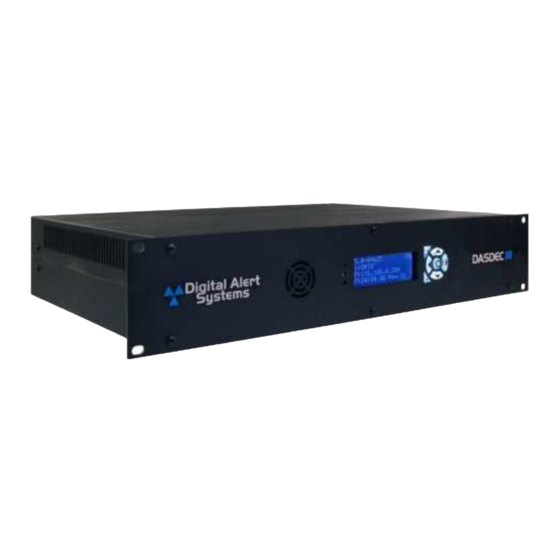
DASDEC-III. Hardware: The DASDEC-III is a 2U rack-mounted EAS device that utilizes standard computer technology in a dedicated chassis with broadcast quality connectors. The PC motherboard uses industry-standard connectors for USB, PS/2, serial, VGA, HDMI, networking, and audio. In addition to the standard motherboard connections, the platforms feature broadcast-quality video, audio, antenna, contact closure, and power connectors. - Page 7 Line 3 – default gateway IP address. • Page Four: • Line 1 – current software version. • Line 2 – device name of the DASDEC-III. Status LEDs Light Emitting Diodes (LEDs) display a variety of system status conditions. Page 7 of 16 Revision 1.0...
-
Page 8: Back Panel
The Expansion Slots are used for optional additional Network Interfaces and additional EAS Audio input hardware. Expansion hardware is only available with the DAS3-EX or the DAS3-GX. Installation The DASDEC-III frame mounts in an EIA-compliant equipment rack by means of four rack screws fastened through the front mounting ears. For safe, long-term reliability: •... -
Page 9: Audio Wiring
Audio Wiring Overview The DASDEC-III platform has two types of analog audio: EAS Monitored Audio and Program Audio. EAS Monitored Audio Inputs feed the internal EAS decoders for processing. Only signals with EAS information should be directed to these inputs. Program Audio connections are used for internal switching of program audio. - Page 10 Refer to the diagram above for the cabling of the AES audio inputs and outputs. EAS Monitoring Inputs Radio signals for the DASDEC-III to decode EAS alerts can be received in two ways: 1. Via internal radios, connect to your site’s antenna via a coaxial connection.
-
Page 11: Video Wiring
DASDEC-III Hardware/Installation Guide Video Wiring HDMI-Video Output is a standard on the DAS3-GX model and optional for all other DASDEC-III units. When enabled, full-screen emergency alert details and accompanying audio is present during alert forwarding and/or alert origination via the HDMI connector on the back panel. -
Page 12: General Purpose Input/Output (Gpio)
Digital Alert Systems DASDEC-III Hardware/Installation Guide General Purpose Input/Output (GPIO) The EAS platform comes standard with two General Purpose Input (GPI) contact closures and two General Purpose Output (GPO) relays. The connector is located on the back panel, a 7-pin pluggable terminal connector is provided. -
Page 13: Serial Port Wiring
Digital Alert Systems DASDEC-III Hardware/Installation Guide Serial Port Wiring Each EAS device has one RS-232 serial port on the back panel. The serial ports connect to and drive a variety of external video character generators and BetaBrite LED signs. The software supports a wide variety of serial protocols, including the most commonly used protocols in legacy EAS equipment, such as TFT Standard and Sage Generic. -
Page 14: Direct Connection
Digital Alert Systems DASDEC-III Hardware/Installation Guide Direct Connection Direct Connection 1. Connect one end of the factory-supplied CAT-5 network crossover cable to the Main Network Interface port at the back of the EAS device and the other end to the network interface port of a standalone PC or laptop computer. -
Page 15: Specifications
Digital Alert Systems DASDEC-III Hardware/Installation Guide Specifications DASDEC-III Specifications DAS3-EL DAS3-EX DAS3-GX Monitoring Audio Inputs: monaural EAS monitoring inputs Two (2) Four (4) Four (4) Internal Monitoring Receivers – Integrated Dual Tri-Band receivers (AM/FM/WX) DAS3-3RADIO DAS3-3RADIO Tunable frequencies: AM 520 to 1720 kHz | FM 76 to 108 MHz | WX 162.4 to 162.55... - Page 16 Digital Alert Systems DASDEC-III Hardware/Installation Guide Connector: 7-pin detachable terminal strip Serial Port – One (1) RS232 data 9 pin “D” connector | Optional USB/4RS232 adds four additional RS-232 ports (5 max.) USB ports: Two (2) USB V2.0/1.1 | Connector: type A sockets Two (2) USB V3.1 | Connector: type A sockets...
Need help?
Do you have a question about the DASDEC-III and is the answer not in the manual?
Questions and answers