
Related Manuals for Magnetrol eclipse Enhanced Model 705


Summary of Contents for Magnetrol eclipse Enhanced Model 705
- Page 1 Enhanced Model 705 Software v3.x Installation and Operating Manual for use in the Hygienic Industries Guided Wave Radar Level Transmitter ASME BPE...
- Page 2 NOTES All rights reserved. Notes contain information that augments or clarifies an MAGNETROL reserves the right to make changes to the operating step. Notes do not normally contain actions. product described in this manual at any time without They follow the procedural steps to which they refer.
-
Page 3: Table Of Contents
Table of Contents 1.0 QuickStart Installation 4.2.2 Field Bends............ 28 1.1 Getting Started............4 4.2.3 Accommodating Non-Linearity..... 29 1.1.1 Equipment and Tools........4 4.3 Electronics Mounting..........30 1.1.2 Configuration Information......5 4.4 Basic Start-Up............30 1.2 QuickStart Mounting..........5 4.4.1 Probe Length..........30 1.2.1 Probe..............5 4.4.2 Blocking Distance and Damping .... -
Page 4: Quickstart Installation
QuickStart Installation The QuickStart Installation procedures provide the key steps for mounting, wiring, and configuring the Eclipse ® level transmitter. These procedures are intended for experi- enced installers of electronic level measurement instruments. See Complete Installation, Section 2.0, for detailed installa- tion instructions. -
Page 5: Configuration Information
1.1.2 Configuration Information Some key information is needed to configure the ECLIPSE transmitter. Complete the following operating parameters table before beginning configuration. Display Question Answer Probe Model What probe model is listed on the model information? (first four digits of probe model number) _____________ Probe Mount Set to flange when using tri-clamp... -
Page 6: Transmitter
Æ Carefully place the probe into the vessel. Align the probe as necessary on the vessel. 1.2.2 Transmitter NOTE: Leave the plastic protective cap in place until ready to install the transmitter. Do not use sealing compound or TFE Black (-) Red (+) tape on probe connection to transmitter as this connection is sealed by a Viton... -
Page 7: Quickstart Configuration
QuickStart Configuration The ECLIPSE transmitter is configured with default values from the factory but can be reconfigured in the shop (disregard any fault messages due to unattached probe). The minimum configuration instructions required in the field follow. Use the information from the operating parameters table in Section 1.1.2 before beginning configuration. -
Page 8: Complete Installation
Model Number Serial Number Electrostatic Discharge (ESD) Handling Procedure Magnetrol electronic instruments are manufactured to the ® highest quality standards. These instruments use electronic components that may be damaged by static electricity pre- sent in most work environments. -
Page 9: Before You Begin
Before You Begin 2.3.1 Site Preparation Each ECLIPSE transmitter is built to match the specific physical specifications of the required installation. Make sure the probe connection is correct for the mounting on the vessel or tank where the transmitter will be placed. See Mounting, Section 2.4. -
Page 10: Prior To Installing A Hygienic Single Rod Probe
2.4.1 Prior to Installing a Hygienic Single Rod Probe (Models 7xF and 7xH) Before installing, ensure the: • Probe has adequate headroom for installation and has unob- structed entry to the bottom of the vessel. • Process temperature, pressure, dielectric, viscosity, and media buildup are within the probe specifications for the installation. -
Page 11: Installing The Transmitter
2.4.2 Installing the Transmitter The transmitter can be ordered for installation as an Integral or Remote configuration. 2.4.2.1 Integral Mount ➀ Remove the protective plastic cap from the top of the ➃ ➁ probe. Store the cap in a safe place in case the transmitter has to be removed later. -
Page 12: Wiring
Wiring Caution: All versions of the ECLIPSE Model 705 transmitter oper- ate at voltages of 11–36 VDC. Higher voltage will damage the transmitter. Wiring Diagram Wiring between the power supply and the ECLIPSE transmitter should be made using 18–22 AWG shielded twisted pair instrument cable. -
Page 13: Intrinsically Safe
2.5.2 Intrinsically Safe An intrinsically safe (IS) installation potentially has flam- mable media present. An approved IS barrier must be installed in the non-hazardous (safe) area. See Agency Drawing – Intrinsically Safe Installation, Section 5.4.2. To install Intrinsically Safe wiring: 1. -
Page 14: Configuring The Transmitter
Configuring the Transmitter The ECLIPSE transmitter is factory-configured but can be reconfigured easily in the shop (disregard error message due to unattached probe). Bench configuration provides a convenient and efficient way to set up the transmitter before going to the tank site to complete the installation. Before configuring the transmitter, collect the operating parameters information (refer to Section 1.1.2). -
Page 15: Transmitter Display And Keypad
2.6.3 Transmitter Display and Keypad The ECLIPSE transmitter has an optional liquid crystal dis- play (LCD) capable of showing two lines of 8 characters each. Transmitter measurements and configuration menu screens are shown on the LCD. The transmitter default display is the measurement screen. It cycles every five seconds to display STATUS, LEVEL, %OUTPUT, and LOOP information (LEVEL, %OUTPUT, and STATUS for Fieldbus version). -
Page 16: Model 705 Menu: Step-By-Step Procedure
2.6.5 Model 705 Menu: Step-By-Step Procedure The following tables provide a complete explanation of the software menus displayed by the ECLIPSE transmitter. Use these tables as a step-by-step guide to configure the transmitter based on a desired measurement type of: •... - Page 17 2.6.5.1 Measurement Type: Level Only (Loop Control = Level) Display Action Comment Senstvty Enter value upward or Allows fine gain adjustment for single rod probes (this parameter downward to sense liquid is password protected for coaxial and twin rod probes). surface LoopCtrl (select)
- Page 18 2.6.5.1 Measurement Type: Level Only (Loop Control = Level) Display Action Comment DispFact (select) Select Yes to display factory parameter menus History (current status) Press Enter to view history Diagnostic Display of exceptions Run Time History Reset Press Enter and select yes Similar to SZ Alarm Reset to clear history HF cable...
-
Page 19: Measurement Type: Level And Volume
2.6.5.2 Measurement Type: Level and Volume (Loop Control = Volume) Display Action Comment *Status* *Volume* Transmitter Display LoopCtrl = Volume *% Out * Transmitter default display showing: Status, Volume, % Output * Loop * and Loop values cycles every 5 seconds Volume xxx vu Transmitter displays Volume in selected units... - Page 20 2.6.5.2 Measurement Type: Level and Volume (Loop Control = Volume) Display Action Comment Select loop current behavior Safety Zone is a user-defined area just below the Blocking Distance. Enable Fault if necessary to ensure safe, reliable high- when level is sensed in safety SZ Fault (select) level readings in critical applications.
- Page 21 2.6.5.2 Measurement Type: Level and Volume (Loop Control = Volume) Display Action Comment Fid Gain Superuser Password Window Factory Parameter Conv Fct xxxx Factory Parameter Calibration parameter Scl Ofst Factory Parameter Calibration parameter Neg Ampl Superuser Password Diagnostic factory setting Pos Ampl Superuser Password Diagnostic factory setting...
-
Page 22: Offset Description
2.6.6 Offset Description The parameter referred to as Lvl Ofst in the ECLIPSE menu LvlUnits is the desired level reading when liquid surface is at the end of the probe. The ECLIPSE transmitter is shipped from the PrbModel 7xF-E factory with Lvl Ofst set to 0. With this configuration, all PrbMount Flange measurements are referenced from the bottom of the probe. -
Page 23: Configuration Using Hart
Configuration Using HART A HART (Highway Addressable Remote Transducer) remote unit, such as a HART communicator, can be used to provide a communication link to the ECLIPSE transmitter. When connected to the control loop, the same system measurement readings shown on the transmitter are shown on the communicator. -
Page 24: Hart Menu - Model 705 3.X
2 Probe Mount 2 Descriptor 2 Manufacturer 2 Enter Password 2 Present Status 3 Measurement Type 3 Date 3 Magnetrol S/N 3 Fiducial Type 3 Status History 4 Level Units 4 Message 4 Level Ticks 4 Firmware Version 4 Fiducial Gain... -
Page 25: Hart Revision Table
2.7.4 HART Revision Table Model 705 HART Version HCF Release Date Compatible with 705 Software Dev V1 DD V1 July 1998 Version 1.2B and earlier Dev V1 DD V2 November 1998 Version 1.2C through 1.3D Dev V3 DD V1 April 1999 Version 1.4A through 1.4C Dev V4 DD V1 October 1999... -
Page 26: Theory Of Operation
Theory of Operation 3.2.1 Micropower Impulse Radar 24 VDC, 4-20 mA Loop Powered MIR (Micropower Impulse Radar) combines TDR (time domain reflectometry), ETS (equivalent time sampling) and modern low power circuitry. This synthesis of technologies brings to the level market a high-speed radar circuit (speed of Transmit Pulse light transmission) at a small fraction of the cost of conven- A reflection is... -
Page 27: Initial Start-Up
ETS is accomplished by scanning the waveguide to collect thousands of samples. Approximately 8 scans are taken per second; each scan gathers more than 30,000 samples. Initial Start-Up The introduction of Guided Wave Radar (GWR) technolo- gy as a method to measure level, increases performance and provides unique solutions beyond traditional level measure- ment methods. -
Page 28: Probe Bends
4.2.2 Field Bends The MAGNETROL ECLIPSE Guided Wave Radar probe can be modified in the field. This includes modifications in length as well as probe bending. Many times this will... -
Page 29: Accommodating Non-Linearity
NOTE: Consider sliding a ⁄ " hose over the electro polished rod to pre- vent damage to the probe during the bending operation. Errors in bending can be corrected by cutting the incorrect portion of the probe and welding a new piece of material to the probe with matching specifications using a full penetra- tion weld to maintain sterility. -
Page 30: Electronics Mounting
Typical applications are within a metallic vessel that pro- vides additional benefit to the technology’s signal efficiency. These factors allow very low gains to reduce the signal-to- noise ratio. The MAGNETROL ECLIPSE unit uses para- meters tagged “Dielectric Range” and “Sensitivity” to adjust the unit’s gain. -
Page 31: Strapping Tables
A bent probe creates a non-linear output relative to actual liquid level in a vessel. To account for this non-linearity, the MAGNETROL ECLIPSE unit has a twenty-point strap- ping table embedded in the device that will correlate a mea- sured level to some configurable point. -
Page 32: Tuning/Optimization
However, as complexi- ties such as probe bending and proximity to disturbances in the vessel are entered into design of the installation, MAGNETROL suggests using the following guidelines to tune a GWR unit. 4.4.4.1 Dielectric Range/Sensitivity Adjust the Dielectric Range and Sensitivity parameters to change the gain of the device. -
Page 33: Strapping Table Configuration
Foaming applications are quite common in Life Sciences liquid level measurement applications and many, if not all, liquid levels can be measured using the MAGNETROL ECLIPSE GWR. However, there is a limit that is dependent upon the dielectric value of the foam. If the value is high enough, the radar signal will not pass through the foam. -
Page 34: Troubleshooting
Troubleshooting The ECLIPSE transmitter is designed and engineered for trouble-free operation over a wide range of operating conditions. Common transmitter problems are discussed in terms of their symptoms and recommended corrective actions. Information on how to handle material buildup on the probe is also provided in this section. W RNING! Explosion hazard. -
Page 35: Status Messages
Status Messages Display Message Action Comment None Normal operating mode Initial None Program is Initializing, level reading held at 4 mA set point. This is a transient condition. DryProbe None Normal message for a dry probe. End of probe signal is being detected. EOP <... - Page 36 Status Messages Display Message Action Comment Lo Temp Present temperature in 1) Transmitter may need to be moved to ensure ambient temperature electronics compartment is is within specification below -40° C 2) Change to remote mount transmitter HiVolAlm Level more than 5% above Verify strapping table is entered correctly.
-
Page 37: Agency Approvals
Agency Approvals AGENCY MODEL APPROVED APPROVAL CATEGORY APPROVAL CLASSES 705-5XXX-1XX Intrinsically Safe Class I, Div. 1; Groups A, B, C, & D 705-5XXX-2XX Class II, Div. 1; Groups E, F, & G T4 Class III, Type 4X, IP66 Entity Explosion Proof ➀ 705-5XXX-3XX Class I, Div. -
Page 38: Agency Specifications (Is Installation)
5.3.2 Agency Specifications – Intrinsically Safe Installation 57-642 ECLIPSE Model 705 Guided Wave Radar Transmitter for Hygienic Industries... -
Page 39: Agency Specifications
5.3.3 Agency Specifications – F fieldbus System OUNDATION 57-642 ECLIPSE Model 705 Guided Wave Radar Transmitter for Hygienic Industries... -
Page 40: Parts
Parts Replacement Parts Part Number 304 ss Single Dual Item Description Compartment Compartment Housing ➀ Electronic module HART with display (SIL 1) Z31-2835-001 89-7254-001 HART without display (SIL 1) Z31-2835-002 HART with display (SIL 2) Z31-2835-003 89-7254-003 HART without display (SIL 2) Z31-2835-004 fieldbus with display Z31-2841-001... -
Page 41: Specifications
Specifications Functional System Design Measurement Principle Guided time-of-flight via time domain reflectometry Input Measured Variable Level, determined by the time-of-flight of a guided radar pulse from transmitter to product surface and back Span 6 inches to 24 feet (15 to 732 cm) Output Type Analog... -
Page 42: Performance (Model 705)
Environment Operating Temperature -40 to +175 °F (-40 to +80 °C) Display Function Operating Temperature -5 to +160 °F (-20 to +70 °C) Storage Temperature -50 to +175 °F (-46 to +80 °C) Humidity 0-99%, non-condensing Electromagnetic Compatibility Meets CE Requirements: EN 61326 Note: Single Rod probes must be used in metallic vessel or stillwell to maintain CE requirement. -
Page 43: Process Conditions
7.3 Process Conditions Hygienic Model (7xF-E or 7xH-x) Maximum +300° F @ 200 psig Process Temperature (+150° C @ 13.7 bar) Maximum 200 psig @ +300 °F Process Pressure (13.7 bar @ 150 °C 10,000 Maximum Viscosity (consult factory if severe agitation/turbulence) Dielectric Range ≥1.9 Hermeticity... -
Page 44: Physical
Physical inches (mm) 2.17 3.02 (55) (77) 45 View 2.53 (64) 4.43 7xF-E: 8.94 (113) Electrical 8.43 (227) Connection (214) 7xH: 9.25 (235) 4.94 (126) 45° View Process Connection 4.28 4.38 Probe (111) (109) Insertion Ø 0.50" (12) Rod Length Ø... -
Page 45: Model Numbers
Model Numbers Transmitter BASIC MODEL NUMBER ECLIPSE Guided Wave Radar Level Transmitter POWER 24 VDC, Two-wire SIGNAL OUTPUT 4–20 mA with HART fieldbus ™ Digital Communication (English only) OUNDATION PROFIBUS PA Digital Communication (English Only) OPTIONS None – SIL 1 Standard Electronics (SFF=84.5%) SIL 2 (Certified) Enhanced Electronics (SFF=91%) ➀... -
Page 46: Probe
Probe BASIC MODEL NUMBER ECLIPSE GWR probe, English unit of measure ECLIPSE GWR probe, Metric unit of measure CONFIGURATION/STYLE Hygienic Single Rod (with PTFE seal) Hygienic Single Rod (with O-Ring seal) MATERIAL OF CONSTRUCTION Hygienic, 316L stainless steel (15 R a EP finish) Hygienic, AL6XN stainless steel (15 R a EP finish) Hygienic, Hastelloy C22 (15 R a EP finish) PROCESS CONNECTION SIZE/TYPE... -
Page 47: Dry Calibration Procedure
20 minutes. 9.1.3 Dry Calibration Verification Bench A Dry Calibration Verification Bench can be manufactured by the user or purchased through MAGNETROL. The part number for a Magnetrol Dry Calibration Verification Bench is P/N 89-7910-002. -
Page 48: Procedure To Verify Calibration Of Eclipse
Procedure to Verify Calibration of ECLIPSE A probe is required for a test bench that is as long as the longest probe installed in the field. The probe must be of the same type as in the field. 9.2.1 Initial Baseline Verification of ECLIPSE The probe and transmitter are calibrated on the actual vessel in the field. -
Page 49: Sample Calibration Verification Document
required range, as determined by the User Requirement Specification (URS), the transmitter passes calibration veri- fication and can be reinstalled on the process. If the transmitter under test fails calibration verification, the transmitter must be installed on the vessel and the probe/transmitter must undergo a complete wet calibration. -
Page 50: Hygienic Probe Rebuild Procedure
10. Hygienic Probe Rebuild Procedure 10.1 Model 7xH 57-642 ECLIPSE Model 705 Guided Wave Radar Transmitter for Hygienic Industries... -
Page 51: Model 7Xf-E
10.2 Model 7xF-E 57-642 ECLIPSE Model 705 Guided Wave Radar Transmitter for Hygienic Industries... -
Page 52: Model 705 Configuration Data Sheet
Model 705 Hygienic Eclipse ® Guided Wave Radar Transmitter Configuration Data Sheet Copy blank page and store calibration data for future reference and troubleshooting. Item Value Value Value Vessel Name Vessel # Process Medium Tag # Electronics Serial # TROUBLESHOOTING Probe Serial # Working Value Non-Working Value... - Page 53 Model 705 Hygienic Eclipse ® Guided Wave Radar Transmitter Configuration Data Sheet Copy blank page and store calibration data for future reference and troubleshooting. Item Value Value Value TROUBLESHOOTING Working Value Non-Working Value FidTicks FidSprd Fid Type Fid Gain Window Conv Fct Scl Ofst Neg Ampl...
-
Page 54: Strapping Table Data Sheet
Model 705 Hygienic Eclipse ® Guided Wave Radar Transmitter Strapping Table Data Sheet Copy blank page and store calibration data for future reference and troubleshooting. Strapping Table Point Level Reading Volume 57-642 ECLIPSE Model 705 Guided Wave Radar Transmitter for Hygienic Industries... -
Page 55: Ppendix : Gwr - Emitted Energy
Appendix A: GWR – Emitted Energy The ECLIPSE Model 705 far exceeds the OSHA health and safety requirements for nonionizing radiation. OSHA Standard 29 CFR 1910.97 covers non-ionization radiation. Section (a)(2)(i) states: “For normal environmental conditions and for incident electro- magnetic energy of frequencies from 10 MHz to 100 GHz, the radiation protection guide is 10 mW/cm (milliwatts per square... -
Page 56: Ppendix B: Indexing Bent Gwr Probes In Vessels
Appendix B: Indexing Bent GWR Probes in Vessels ECLIPSE hygienic GWR probes are often bent to avoid obstructions in a vessel or to position the tip of the probe at the heel of a vessel in order to measure as low in the vessel as possible. - Page 57 The easiest way to achieve the match-mark is to make a ver- tical mark on both the vessel ferrule and the GWR probe process adapter. This mark can be something as simple as a permanent Magic Marker line or a vertical chisel mark. In either case, the indexing mark will match the alignment of the bent probe within a vessel.
-
Page 58: Ppendix C: Segmented Probes
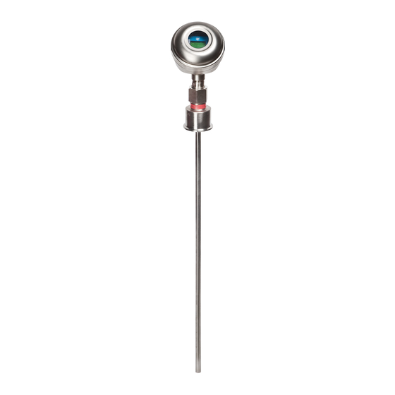
Appendix C: Segmented Probes Stainless Steel Housing with Model 7xH Hygienic probe ECLIPSE Model 705 transmitter in a 304 SS housing for use in a variety of hygienic applications. 0.5-inch diameter 316L SS probe with a 15Ra MAX surface finish is available with lengths up to 244" and with Tri-Clover type connection sizes from 1"... - Page 59 NOTES 57-642 ECLIPSE Model 705 Guided Wave Radar Transmitter for Hygienic Industries...
- Page 60 MAGNETROL local representative or by MAGNETROL will repair or replace the control at no cost contacting the factory. Please supply the following to the purchaser (or owner) other than transportation if: information: 1.
Need help?
Do you have a question about the eclipse Enhanced Model 705 and is the answer not in the manual?
Questions and answers