Sign In
Upload
Download
Table of Contents
Contents
Add to my manuals
Delete from my manuals
Share
URL of this page:
HTML Link:
Bookmark this page
Add
Manual will be automatically added to "My Manuals"
Print this page
×
Bookmark added
×
Added to my manuals
Manuals
Brands
Magnetrol Manuals
Transmitter
ES Modulevel
Installation and operating manual
Magnetrol ES Modulevel Installation And Operating Manual
Top hat assembly design, digital ii modulevel with hart communication and analog modulevel electronic liquid level transmitters
Hide thumbs
1
2
Table Of Contents
3
4
5
6
7
8
9
10
11
12
13
14
15
16
17
18
19
20
21
22
23
24
25
26
27
28
29
30
31
32
33
34
35
36
37
38
39
40
41
42
43
44
45
46
47
48
49
50
51
52
page
of
52
Go
/
52
Contents
Table of Contents
Troubleshooting
Bookmarks
Table of Contents
Table of Contents
1 0 Complete Installation
Unpacking
Electrostatic Discharge (ESD)
Before You Begin
Site Preparation
Equipment and Tools
Operational Considerations
Mounting
Installing a Tank Top Mounted Modulevel
Installing a Chamber Type Modulevel
2 Analog EZ Modulevel Wiring and Calibration
Integral Transmitter Wiring
Remote Transmitter Wiring
Hazardous Location Wiring
Calibrating the Analog EZ Modulevel
Direct Acting Field Calibration
Reverse Acting Field Calibration
Bench Calibration
3 Digital es II Modulevel Wiring and Calibration
Integral Transmitter Wiring
Remote Transmitter Wiring
Hazardous Location Wiring
Digital es II Push-Button Calibration
Push-Button Field Calibration
Push-Button Bench Calibration
Digital Meter Calibration
Interface Calibration
Calibration in Process Liquids
Calibration in Water Only for Interface of Another Liquid over Water
Calibration in Water Only for Interface of Two Other Liquids
Lower S.G. Less than or Equal to 1.0
Lower S.G. Greater than 1.0
Configuration Using HART
Connections
Display Menu
Basic Field Calibration Using Hart HHC
Hart Menu
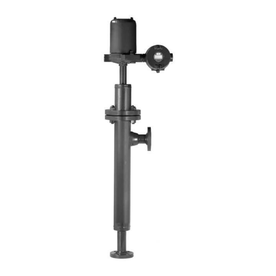
48-618 ES/EZ Modulevel Displacer Level Transmitter (Top hat Assembly Design
4 Reference Information
Description
Theory of Operation
Displacer Buoyancy
Lvdt
Troubleshooting
Maintenance of Analog EZ Modulevel
Replacing Transmitter PC Board
Replacing Power Supply PC Board
Replacing LVDT
Checking the LVDT Winding Resistance
Maintenance of Digital es II Modulevel
Replacing Transmitter PC Board
Replacing LVDT
Checking the LVDT Winding Resistance
Agency Approvals
FM (Factory Mutual)
CSA (Canadian Standards Association)
CENELEC (Comiteí Européen de Normalisation Electotechnique)
Parts
Replacement PC Boards
Transmitter Head Parts
Recommended Spare Parts
Mechanical Replacement Parts
Upgrade to ESII Electronics
ES to es II Conversion
EZ to es II Conversion
Specifications
Functional
Performance
Physical
Model Numbers
Models for Steam Applications (Max. 600 Lbs.)
Models for Steam Applications
(900-2500 Lbs.)
Models for Non-Steam Applications (Max. 600 Lbs.)
Glossary
Advertisement
Quick Links
1
Calibrating the Analog Ez Modulevel
2
Troubleshooting
3
Model Numbers
Download this manual
Installation and Operating Manual
ES/EZ Modulevel
Top Hat Assembly Design
Digital ES II Modulevel
with HART
and Analog EZ Modulevel
Electronic Liquid Level
Transmitters
Communication
®
®
Table of
Contents
Previous
Page
Next
Page
1
2
3
4
5
Advertisement
Table of Contents
Need help?
Do you have a question about the ES Modulevel and is the answer not in the manual?
Ask a question
Questions and answers
Related Manuals for Magnetrol ES Modulevel
Transmitter Magnetrol E3A Operating Manual
E3 modulevel liquid level displacer transmitter with foundation fieldbus digital output (60 pages)
Transmitter Magnetrol E3A Modulevel Installation And Operating Manual
Digital e3 modulevel with hart and pactware communications liquid level displacer transmitter (48 pages)
Transmitter Magnetrol Enhanced Model 705 Operating Manual
Foundation fieldbus digital output (56 pages)
Transmitter Magnetrol EZ Modulevel Installation And Operating Manual
Top hat assembly design, digital ii modulevel with hart communication and analog modulevel electronic liquid level transmitters (52 pages)
Transmitter Magnetrol Eclipse 706-512 Manual
High performance guided wave radar level transmitter (16 pages)
Transmitter Magnetrol 2xx Operating Manual
Magnetostrictive level transmitter (36 pages)
Transmitter Magnetrol Eclipse 706GWR Safety Manual
Radar level transmitter (16 pages)
Transmitter Magnetrol Kotron II Series 801 Instruction Manual
Rf capacitance transmitter for level/flow/volume (28 pages)
Transmitter Magnetrol eclipse Enhanced Model 705 Installation And Operating Manual
Guided wave radar level transmitter (60 pages)
Transmitter Magnetrol R82 Installation And Operating Manual
Pulse burst radar level transmitter (64 pages)
Transmitter Magnetrol Eclipse 706GWR Installation And Operating Manual
High performance, 4th generation guided wave radar level transmitter (108 pages)
Transmitter Magnetrol Eclipse 705 Installation And Operating Manual
Guided wave radar level transmitter (68 pages)
Transmitter Magnetrol Orion Jupiter Enchanced 2 Series Manual
Magnetostrictive level transmitter (36 pages)
Transmitter Magnetrol Eclipse 706 Operating Manual
High performance, 4th generation guided wave radar level transmitter with foundation fieldbus (68 pages)
Transmitter Magnetrol Jupiter JM4 Operating Manual
Hart to modbus adaptor; guided wave radar level transmitter; magnetostrictive level transmitter; pulse burst radar level transmitter (124 pages)
Transmitter Magnetrol Jupiter JM4 Installation And Operating Manual
Magnetostrictive level transmitter (35 pages)
This manual is also suitable for:
Ez modulevel
Table of Contents
Save PDF
Print
Rename the bookmark
Delete bookmark?
Delete from my manuals?
Login
Sign In
OR
Sign in with Facebook
Sign in with Google
Upload manual
Upload from disk
Upload from URL


Need help?
Do you have a question about the ES Modulevel and is the answer not in the manual?
Questions and answers