Magnetrol Jupiter JM4 Installation And Operating Manual
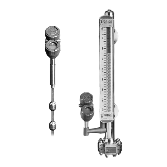
Magnetostrictive level transmitter
Hide thumbs
Also See for Jupiter JM4:
- Operating manual (124 pages) ,
- Installation and operating manual (76 pages) ,
- Safety manual (16 pages)

Related Manuals for Magnetrol Jupiter JM4


Summary of Contents for Magnetrol Jupiter JM4
- Page 1 Model JM4 HART Installation and Operating Manual Software v1.x Magnetostrictive Level Transmitter...
-
Page 2: Table Of Contents
Performance specifications are effective with date of issue Jupiter JM4 Magnetostrictive Transmitter Conventions Used in this Manual and are subject to change without notice. Magnetrol reserves Certain conventions are used in this manual to convey the right to make changes to the product described in this specific types of information. -
Page 3: Installation Prep
Electrostatic Discharge Handling 1.1.6 Mounting Transmitter Head Magnetrol/Orion’s electronic instruments are manufactured to To attach the JM4 transmitter head to the probe, place the the highest quality standards. These instruments use electronic female transmitter connection (Figure 1-2) over the male probe components that may be damaged by static electricity present in Fig. -
Page 4: Remote Mount Transmitter Head
1.1.7 Remote Mount Transmitter Head For applications with possible clearance or transmitter accessibil- ity issues, the JM4 is available with a remote mount transmitter head. This transmitter head comes with a 3 or 12 ft (0.91 or 3.66 m) heavily shielded cable and can be mounted onto nearby objects. -
Page 5: Installation On Atlas Vs. Aurora
Mounting for Direct Insertion 4. The upper clamp will need to be open to a large enough diam- eter to be able to mount to the MLI as well as the probe. The upper clamp should be positioned just above the 3/4” NPT 1.3.1 Available Configurations threads. -
Page 6: Centering Disc
1.3.3 Centering Disc 6. Replace and tighten the cover to the transmitter wiring compartment before applying power. All Jupiter model JM4 transmitters that come with a stilling well are also provided with a centering disc to prevent the probe from 1.4.2 Intrinsically Safe making contact with the stilling well. -
Page 7: Configuration
1.5.2.1 Navigating the Menu 4. Connect an Earth ground wire to the nearest green ground screw per local electrical code (not shown in illustration). UP moves to the previous item in the menu branch. 5. Connect the positive supply wire to the (+) terminal and the DOWN moves to the next item in the menu branch. -
Page 8: Entering Numeric Data Using Increment/Decrement
1.5.2.4 Entering Numeric Data Using Increment/Decrement The default User Password installed in the transmitter at the factory is 0. With a password of 0, the transmitter is no longer Use this method to input the following data into parameters password protected, and any value in the basic user menus can such as Damping and Failure Alarm. -
Page 9: Auto-Configuration/Reset New Probe Diagnostic
The Home Screen presentation can be customized by viewing or 1.5.5 Auto-Configuration/Reset New Probe Diagnostic hiding some of these items. See DISPLAY CONFIG under the Each JM4 probe has its own set of configuration parameters DEVICE SETUP menu in Section 1.6.4 HART Menu - Model stored inside. -
Page 10: Model Jm4 Configuration Menu - Device Setup
1.5.6 Model JM4 Configuration Menu – Device Setup 1.5.6 Model JM4 Configuration Menu – Device Setup Home Screen Main Menu Home Screen Identity Device Setup Product Name (read only) Main Menu Orion S/N (read only) DIGITAL BOARD (read only) Identity Vessel Type: Vessel Dimensions: Device Setup ANALOG BOARD (read only) Basic Config [Physical Dev Tag] (read only) Rectangular Radius... - Page 11 1.5.6 Model JM4 Configuration Menu – Device Setup 1.5.6 Model JM4 Configuration Menu – Device Setup Home Screen Home Screen Main Menu Main Menu Language: Identity Identity Device Setup Device Setup Blocking Distance: English Basic Config Basic Config 0 to 50 feet Français Volume Config Volume Config (0 m to 15 m) Deutsch I/O Config I/O Config...
-
Page 12: Configuration Using Hart
1.6 Configuration using HART 1.5.6 Model JM4 Configuration Menu – Device Setup Home Screen A HART (Highway Addressable Remote Transducer) remote Main Menu unit, such as a HART communicator, can be used to provide a communication link to the Jupiter Model JM4 transmitter. Device Setup Identity Elec Temp Offset: When connected to the control loop, the same system measure- Basic Config -60 to +60... - Page 13 1.6.4 HART Menu – Model JM4 1.6.4 HART Menu – Model JM4 NOTE: Numbered menu boxes below correspond to numbered tables on Section 1.6.5. NOTE: Numbered menu boxes below correspond to numbered tables on Section 1.6.5. 1 PV 1 PV 2 PV Analog Output 2 PV Analog Output 3 PV % Output 3 PV % Output 4 Device Setup...
-
Page 14: Hart Menu Items
1.6.4 HART Menu – Model JM4 1.6.5 HART Menu Items NOTE: Numbered menu boxes below correspond to numbered tables on Section 1.6.5. 1 PV Display Description 2 PV Analog Output Digital representation that tracks the Analog Output Number 1, under normal operating modes. 3 PV % Output 4 Device Setup Level of material on the probe. - Page 15 1.6.5 HART Menu Items (contd.) 1.6.5 HART Menu Items (cont.) Display Description Display Description Enter Password Enter Password The desired measurement mode of operation. Measurement Type Text that is associated with the Field Device installation. This text can be used by the user in (Selection of Measurement Type may be constrained by the Probe Model.) any way. A recommended use is as a unique label to a plant that correlates to a Field Device A menu that allows for setting the measurement units used by the transmitter. label, a plant drawing, or on a Control System. This variable is also used as a type of data link System Units layer address handle. Desired level reading when liquid surface is at the tip of the probe. Functions exactly like Tag except the size is larger (maximum of 32 ISO Latin 1 characters).
- Page 16 1.6.5 HART Menu Items (cont.) 1.6.5 HART Menu Items (cont.) Display Description Display Description Enter Password Enter Password An index location that indicates which Field Device dynamic variable has been mapped into Language Enables choice of language to be displayed on the LCD. PV is the Primary Variable dynamic variable. Status Symbol Enables NE 107 Status symbol to be displayed on Home Screen. PV 4 mA Set Point Enter 4 mA point in level units Enables Long Tag to be displayed on the Home Screen. Long Tag Enter 20 mA point in level units PV 20 mA Set Point Enables a bar graph (displaying the Primary Variable in percent) to be displayed on the Home Digital representation that tracks the Analog Output Number 1, under normal operating...
- Page 17 1.6.5 HART Menu Items (cont.) 1.6.5 HART Menu Items (cont.) Display Description Display Description Enter Password Minimum distance that can be achieved between the magnets on adjacent floats when the Minimum Separation floats are touching each other. Distance below the reference point within which level is ignored. Blocking Distance (Operation is undefined when the liquid level is within the blocking distance.) Present Sensitivity (gain) of the instrument. Sensitivity Default setting depends on the value in the probe memory and is suitable for most installations. An offset value to be used to force the transmitter to output the exact Level or Distance. This Level Trim Refer to I & O manual before adjusting.
- Page 18 1.6.5 HART Menu Items (cont.) 1.6.5 HART Menu Items (cont.) Display Description Display Description Shows the Present Status (health) of the transmitter. Present Status Present Temperature Present temperature measured in the electronics compartment. Event History The history of the 10 most recent diagnostic events. Max Temperature Maximum temperature measured in the electronics compartment. Advanced Menu containing Advanced Diagnostic parameters. Min Temperature Minimum temperature measured in the electronics compartment.
- Page 19 1.6.5 HART Menu Items (cont.) 1.6.5 HART Menu Items (cont.) Display Description Display Description Echo Graph Listing of Device Variables that can be selected to be saved in the internal data log feature of Trending Variables Curve 1 Select the primary curve to display. the device. Curve 2 Select the secondary curve to display. Time Setup A menu that allows the user to set the time span and sample interval for the Data Log.
-
Page 20: Reference Information
2.0 Reference Information PACTware PC Program The JUPITER Model JM4 offers the ability to perform more This section presents an overview of the operation of the Jupiter advanced diagnostics such as Trending and Echo Curve analysis magnetostrictive transmitter, information on troubleshooting using a PACTware DTM. - Page 21 2.3.2 Troubleshooting Table As mentioned above, the indicators can be assignable (via the a DTM or host system) by the user to any (or none) of the Problem Solution NAMUR recommended Status Signal categories: Failure, Func- Analog Output Error Blank display Ensure local Keypad / LCD is properly installed.
-
Page 22: Diagnostics (Namur Ne 107)
ITEMS from the top level of the DIAGNOSTICS transmitter tree. New Probe Probe memory contents On Display, go to ‘Reset New Probe’ and enter password. When Present Status is highlighted, the highest MAGNETROL disagree with EEPROM image priority active diagnostic indicator (numerically lowest in Table DIAGNOSTICS Analog Board Error No response from co- Consult Factory. -
Page 23: Configuration Information
2.4 Configuration Information Vessel Types 2.4.1 Volumetric Capability Selecting Measurement Type = Volume and Level allows the Model JM4 transmitter to measure volume as the Primary Mea- sured Value. 2.4.1.1 Configuration Using Built-In Vessel Types The following table provides an explanation of each of the Sys- tem Configuration parameters required for volume applications that use one of the nine Vessel Types. -
Page 24: Reset Function
2.4.1.2 Configuration Using Custom Table 2.4.2 Reset Function If none of the nine Vessel Types shown can be used, a Custom A parameter labeled “Reset Parameter” is located at the end of Table can be created. A maximum of 30 points can be used to the DEVICE SETUP/ADVANCED CONFIG menu. -
Page 25: Agency Approvals
SPECIAL CONDITIONS OF USE: Agency Approvals 1. The enclosure contains aluminum and is considered to present a potential risk of ignition by impact or friction. Care must be taken during installation and use to prevent impact or friction. 2. To maintain the T4 temperature code care shall be taken to ensure the enclosure temperature does not exceed 70ºC (158ºF). -
Page 26: Agency Specifications - Fm/Csa Intrinsically
Ii (Imax) = 380 mA Pi = 5.32 W Ci = 440pF Li = 2.7µH Leakage current < 50µA "SEE NOTE 2" JUPITER JM4-51XX-XXX Any FM/CSA Approved Intrinsically Safe Associated Apparatus with Parameters suitable for the FISCO Concept. FOR PROPER INSTALLATION REFERENCE ALL... -
Page 27: Specifications
2.5 Specifications 2.5.1 Functional/Physical Humidity 0 to 99%, non-condensing 2.5.1 Functional/Physical Electromagnetic Compatibility Meets CE requirement (EN 61326) and NAMUR NE 21 System Design Surge Protection Meets CE EN 61326 (1000V) Measurement Principle Magnetostriction-based mechanical response signal ANSI/ISA-S71.03 Class SA1 (Shock); ANSI/ISA-S71.03 Class VC2 Shock/Vibration Input (Vibration) Measured Variable Level, response signal time of flight Performance 6 inches to 400 inches (15 cm to 999 cm) Span Linearity 0.030 in. or 0.01% of probe length, whichever is greater Output Accuracy ±0.01% full scale or 0.05 in, whichever is greater Type 4 to 20 mA with HART: 3.8 mA to 20.5 mA useable (per NAMUR NE43) Resolution .014” (.35 mm) Foundation fieldbus : H1 (ITK Ver. 6.1.1) Repeatability... -
Page 28: Physical Specifications - Transmitter
2.5.4 Physical Specifications - Transmitter 2.5.4 Physical Specifications - Transmitter inches [mm] 3.39 4.18 inches [mm] 106.2 15.16 20.23 16.42 385.1 513.9 3.77 95.9 8.35 10.04 212.1 255.1 5.09 129.4 45° 3.96 External Top Mount External Top Mount External Top Mount Transmitter Head 100.7 Offset Offset, Cryo 22.92 18.92 16.92... -
Page 29: Power Supply Requirements
2.6 Model Number 2.5.5 Power Supply Requirements Transmitter 1 2 3 | BASIC MODEL NUMBER 2.5.5.1 Safe Operating Area Jupiter 4th Generation Magnetostrictive Level Transmitter 4 | POWER 24 VDC Two Wire Safe Operating Area 5 | SIGNAL OUTPUT 4-20 mA with HART 1136 Foundation Fieldbus Communications Loop... - Page 30 Model Number Model Number Continued Direction Insertion Probe Direction Insertion Probe 1 | TECHNOLOGY 8 | INSTALLATION CONSIDERATIONS Jupiter Magnetostrictive Probes - Model JM4 Direct Insertion unit mounted in vessel without stilling well. Probe centering disc not required. Direct Insertion unit mounted in chamber, bridle, or stilling well. Probe centering disc required. 2 | MEASUREMENT SYSTEM 9 | CONSTRUCTION CODES English...
- Page 31 Model Number Model Number Continued External Mount Probe External Mount Probe 1 | TECHNOLOGY 8 | INSTALLATION CONSIDERATIONS Jupiter Magnetostrictive Probes - Model JM4 No mounting clamps required. Chamber/Clamp Sizes for MLI Mount Without High Temperature Insulation 2” (or if digit 20 of MLI model code is 1, 2, or 7) 2 | MEASUREMENT SYSTEM 2 1/2” (or if digit 20 of MLI model code is 3, 4, 5, or 6) English 3” (or if digit 20 of MLI model code is A, B, C, or D)
-
Page 32: Glossary
Parts Glossary 2.7.1 Replacement Parts Accuracy The maximum positive and negative % devia- Ground An electrical connection to the Earth’s potential tion from the actual value over the total span. that is used as a reference for the system and electrical safety. ANSI American National Standards Institute. - Page 33 The process measurement is achieved supply the following information: by varying the current of the loop. Also called Loop Pow- Magnetrol/Orion will repair or replace the control Multidrop The ability to install, wire, or communicate ered. at no cost to the purchaser (or owner) other than 1.
- Page 34 JUPITER™ MODEL JM4 MAGNETOSTRICTIVE LEVEL TRANSMITTER APPLICATION DATA SHEET Direct Insertion Configuration Notes & Sketch Area 2105 Oak Villa Boulevard • Baton Rouge, Louisiana • 70815 • P: 225.906.2343 • F: 225.906.2344 • www.orioninstruments.com Customer Contact Name Quote Reference # Phone # E-mail Address Jupiter®...
- Page 35 2105 Oak Villa Boulevard • Baton Rouge, Louisiana 70815 • 225-906-2343 • Toll Free 866-55-ORION • Fax 225-906-2344 • www.orioninstruments.com Copyright © 2016 Magnetrol Interna onal, Incorporated. All rights reserved. Printed in the USA. Magnetrol & Magnetrol logotype and Orion Instruments & Orion logotype are registered trademarks of Magnetrol International, Incorporated. HART® is a registered trademark of the HART Communication Foundation PACTware™ is trademark of PACTware Consortium...
Need help?
Do you have a question about the Jupiter JM4 and is the answer not in the manual?
Questions and answers