Sign In
Upload
Manuals
Brands
Magnetrol Manuals
Transmitter
Enhanced Model 705
Magnetrol Enhanced Model 705 Manuals
Manuals and User Guides for Magnetrol Enhanced Model 705. We have
2
Magnetrol Enhanced Model 705 manuals available for free PDF download: Installation And Operating Manual, Operating Manual
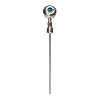
Magnetrol Enhanced Model 705 Installation And Operating Manual (60 pages)
Guided Wave Radar Level Transmitter
Brand:
Magnetrol
| Category:
Transmitter
| Size: 2 MB
Table of Contents
Table of Contents
3
1 Quickstart Installation
4
Getting Started
4
Equipment and Tools
4
Configuration Information
5
Quickstart Mounting
5
Probe
5
Transmitter
6
Quickstart Wiring
6
Quickstart Configuration
7
2 Complete Installation
8
Unpacking
8
Electrostatic Discharge (ESD) Handling Procedure
8
Before You Begin
9
Site Preparation
9
Equipment and Tools
9
Operational Considerations
9
Mounting
9
Prior to Installing a Hygienic Single Rod Probe
10
To Install a Model 7Xf or Model 7Xh
10
Single Hygienic Probe
10
Installing the Transmitter
11
Integral Mount
11
Remote Mount
11
Wiring
12
General Purpose or Non-Incendive
12
(CI I, DIV 2)
12
Intrinsically Safe
13
Explosion Proof
13
Configuring the Transmitter
14
Operating Parameters
14
Setting up for Bench Configuration
14
Transmitter Display and Keypad
15
Password Protection (Default = 0)
15
Model 705 Menu: Step-By-Step Procedure
16
Measurement Type: Level Only
16
Measurement Type: Level and Volume
19
Offset Description
22
Configuration Using HART
23
Connections
23
Display Menu
23
HART Menu - Model 705 3.X
24
HART Revision Table
25
3 Reference Information
25
Description
25
Theory of Operation
26
Micropower Impulse Radar
26
Time Domain Reflectometry (TDR)
26
Equivalent Time Sampling (ETS)
26
4 Initial Start-Up
27
Probe Location
27
Probe Bends
28
Shallow Bends
28
Field Bends
28
Accommodating Non-Linearity
29
Electronics Mounting
30
Basic Start-Up
30
Probe Length
30
Blocking Distance and Damping
30
Strapping Tables
31
Tuning/Optimization
32
Dielectric Range/Sensitivity
32
Pactware Echocurve
32
Blocking Distance
32
Echo Curves in Dry and Filled States
32
Strapping Table Configuration
33
Additional Considerations
33
5 Troubleshooting
34
Troubleshooting System Problems
34
Status Messages
35
Agency Approvals
37
Agency Specifications (XP Installation)
37
Agency Specifications (IS Installation)
38
Agency Specifications
39
Fieldbus)
39
6 Parts
40
Replacement Parts
40
Recommended Spare Parts
40
Parts 6.1 Replacement Parts
40
7 Specifications
41
Functional
41
O-Ring (Seal) Selection Chart
41
Specifications 7.1 Functional
41
Performance (Model 705)
42
Process Conditions
43
Probe Specifications
43
Physical
44
8 Model Numbers
45
Transmitter
45
Probe
46
9 Dry Calibration Procedure
47
Calibration Verification
47
Wet Calibration Verification of ECLIPSE
47
Dry Calibration Verification of ECLIPSE
47
Dry Calibration Verification Bench
47
Procedure to Verify Calibration of ECLIPSE
48
Initial Baseline Verification of ECLIPSE
48
Subsequent Calibration Verification
48
Sample Calibration Verification Document
49
10 Hygienic Probe Rebuild Procedure
50
Model 7Xh
50
Model 7Xf-E
51
Model 705 Configuration Data Sheet
52
Strapping Table Data Sheet
54
Ppendix : GWR - Emitted Energy
55
Appendix A: GWR -Emitted Energy
56
Ppendix B: Indexing Bent GWR Probes in Vessels
56
Appendix B: Indexing Bent GWR Probes in Vessels
58
Ppendix C: Segmented Probes
58
Advertisement
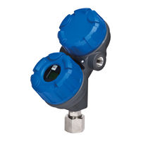
Magnetrol Enhanced Model 705 Operating Manual (56 pages)
Foundation fieldbus digital output
Brand:
Magnetrol
| Category:
Transmitter
| Size: 1 MB
Table of Contents
1 Found Tion
3
Table of Contents
3
Description
4
Overview
4
Benefits
5
Device Configuration
5
Intrinsic Safety
6
Link Active Scheduler (LAS)
7
2 Quickstart Installation
7
Getting Started
7
Equipment and Tools
7
Quickstart Mounting
8
Probe
8
Transmitter
8
Quickstart Wiring
9
Quickstart Configuration
10
3 Complete Installation
11
Unpacking
11
Before You Begin
12
Site Preparation
12
Equipment and Tools
12
Operational Considerations
12
Mounting
12
Installing a Coaxial Probe
13
To Install a Coaxial Probe
13
Installing a Twin Rod Probe
14
To Install a Rigid Twin Rod Probe
14
To Install a Model 7X7 Standard Flexible Twin Rod Probe
15
Installing a Single Rod Probe
15
Installing a Rigid Probe
16
Installing a Flexible Probe
16
Installation Guidelines-Models 7X2/7X5 Bulk Solids Probes
17
Applications
17
Mounting Recommendations
17
To Install a Bulk Solids Single Rod Probe
18
Installing the Transmitter
19
Integral Mount
19
Remote Mount
19
4 Function Blocks
20
Overview
20
Universal Fieldbus Block Parameters
20
Resource Block
21
Transducer Block
24
Transducer Block Parameters
24
Password Parameters
24
Configuration Parameters
25
Offset Description
26
Calibration Parameters
27
Factory Parameters
27
Firmware Version
28
Analog Input Block
28
AI Block Parameters
28
Local Display of Analog Input
30
Transducer Block Parameters
30
AI out Display Screens
31
PID Block
32
PID Block Parameters
32
5 Model 705 FOUND TION Fieldbus ™ Menu
35
Measurement Type: Level Only
35
6 Diagnostic Parameters
38
Simulation Feature
39
7 Reference Information
40
Troubleshooting
40
Troubleshooting System Problems
40
Status Messages
41
FF Segment Checklist
43
Agency Approvals
44
Agency Specifications
45
OUNDATION Fieldbus System
45
Specifications
46
Functional
46
Performance - Model 705
47
Performance - Model 705 Interface
47
Parts
48
Replacement Parts
48
Recommended Spare Parts
48
Model Numbers
49
Transmitter
49
Probe
50
References
53
Ppendix - Transducer Block Parameters
53
Appendix - Transducer Block Parameters
54
Configuration Data Sheet
54
Advertisement
Related Products
Magnetrol 2xx
Magnetrol 82 CE Series
Magnetrol E3A Modulevel
Magnetrol E3B Modulevel
Magnetrol E3C Modulevel
Magnetrol E3D Modulevel
Magnetrol E3E Modulevel
Magnetrol E3F Modulevel
Magnetrol Echotel 300
Magnetrol Echotel 301
Magnetrol Categories
Switch
Transmitter
Measuring Instruments
Radar
Accessories
More Magnetrol Manuals
Login
Sign In
OR
Sign in with Facebook
Sign in with Google
Upload manual
Upload from disk
Upload from URL