Table of Contents
Advertisement
Quick Links
Download this manual
See also:
Operating Manual
Advertisement
Table of Contents
Troubleshooting

Subscribe to Our Youtube Channel
Related Manuals for Magnetrol E3A Modulevel


Summary of Contents for Magnetrol E3A Modulevel
- Page 1 E3 Modulevel ® Installation and Operating Manual Digital E3 Modulevel with ® H RT and P CTware ® ™ Communications Liquid Level Displacer Transmitter...
- Page 2 In this manual, a caution box indicates a potentially determined to be covered under the warranty; then, hazardous situation which, if not avoided, may result in MAGNETROL will repair or replace the control at no cost minor or moderate injury. to the purchaser (or owner) other than transportation.
-
Page 3: Table Of Contents
E3 Modulevel ® Displacer Level Transmitter Installation, Operation and Maintenance Manual Table of Contents 1.0 QuickStart Installation 3.0 Reference Information 1.1 Getting Started............4 3.1 Description .............27 1.1.2 Equipment and Tools ........4 3.2 Theory of Operation..........27 1.1.2 Configuration Information......4 3.2.1 Displacer/Range Spring ........27 1.2 QuickStart Mounting..........4 3.2.2 LVDT ............27 1.2.1 Tank Top............4... -
Page 4: Quickstart Installation
QuickStart Installation Getting Started 1.1.1 Equipment and Tools No special equipment or tools are required to install E3 Modulevel ® . The following items are recommended: • Wrenches, flange gaskets and flange bolting appropriate for process connection(s) • Flat-blade screwdriver •... -
Page 5: External Chamber
2. Using a level, verify that the vessel mounting flange is level in all directions within 3°. 3. Position the head flange gasket on the vessel flange and gen- tly lower the displacer into the vessel. To prevent damage to the stem/spring assembly, avoid tipping the unit or, in any way, putting lateral forces on the stem. -
Page 6: Quickstart Configuration
QuickStart Configuration The E3 MODULEVEL transmitter comes configured with default values from the factory but can be reconfigured in the shop. The minimum configuration instructions required in the field follow. Use the information from the operating parameters table in Section 1.1.2 before beginning configuration. -
Page 7: Complete Installation
Model Number Serial Number Electrostatic Discharge (ESD) Handling Procedure Magnetrol electronic instruments are manufactured to the ® highest quality standards. These instruments use electronic components which may be damaged by static electricity present in most work environments. -
Page 8: Before You Start
Before You Begin 2.3.1 Site Preparation Each E3 MODULEVEL transmitter is built to match the physical specifications of the required installation. Ensure that the process connection(s) on the vessel matches the MODULEVEL process connection(s). See Mounting, Section 2.4. Ensure that the wiring between the power supply and MODULEVEL transmitter are complete and correct for the type of installation. -
Page 9: Mounting
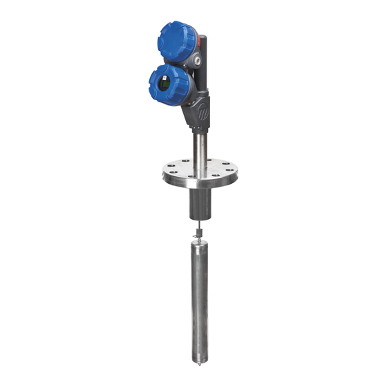
Mounting The E3 MODULEVEL transmitter can be mounted to a tank using a variety of configurations and process connections. Generally, either a threaded, welded or flanged connection is used with an external cage. A flanged connection is always used on a tank top model. For information about the sizes and types of connections available, see Model Numbers, Section 3.7. -
Page 10: External Chamber Installation
• A stilling well is installed for applications where continuous agitation is present. The stilling well must be vertically level so as not to restrict displacer movement. See Figure 6 for a typical stilling well installation. • The process temperature, pressure and specific gravity are within the unit’s specifications for installation. -
Page 11: Wiring
To install: 1. Align the MODULEVEL process connections with those on the vessel and attach accordingly, based upon the connection type. Appropriate gaskets and bolting will be required for flanged connections. Install the flange bolts and nuts and tighten alternating nuts in a star pattern. Flange bolting torque specifications are listed on page 9. -
Page 12: General Purpose Or Non-Incendive (Cl I, Div. 2)
2.5.1 General Purpose or Non-Incendive (Cl I, Div. 2) A general purpose installation does not have flammable media present. Areas rated non-incendive (Cl I, Div. 2) have flammable media present only under abnormal conditions. No special electrical connections are required so standard installation methods may be followed. -
Page 13: Intrinsically Safe
2.5.2 Intrinsically Safe An intrinsically safe (IS) installation potentially has flamma- (-) negative (+) positive ble media present. An approved IS barrier must be installed in the non-hazardous (safe) area. Consult factory for agency drawing. To install Intrinsically Safe wiring: Power Supply 1. - Page 14 NOTE: When operated from a 24 VDC source, the maximum allow- able loop resistance is 620 ohms for E3 MODULEVEL units. When using HART, a loop resistance of 250 to 450 ohms must be placed in series with the E3 MODULEVEL. See Figure 16 on page 39.
-
Page 15: Configuring The Transmitter
Configuring the Transmitter The E3 MODULEVEL transmitter comes calibrated from the factory. Information on configuring the transmitter using a HART communicator is given in Configuration Using HART, Section 2.7. 2.6.1 Operating Parameters Some key information is needed to configure the E3 trans- mitter. -
Page 16: Password Protection (Default = 0)
2.6.3 Password Protection (Default = 0) The E3 transmitter is password protected to restrict access to certain portions of the menu structure that affect the operation of the system. When the proper password is entered, an exclamation point (!) appears as the last charac- ter of the first line of the display. -
Page 17: Measurement Type: Level
The numbers are not shown on the display. They are pro- vided as a reference. The third column provides the actions to take when configuring the transmitter. Additional information or an explanation of an action is given in the fourth column. Configuration tips: If “Calselct”... - Page 18 2.6.5.1 Measurement Type: Level Only (cont.) Display Action Comment Trim Lvl xx.xx lu Enter value to adjust Level Fine tune level reading reading Trim 4 xxxx Fine tune 4 mA point Adjust setting (0 – Trim 20 value) to output exactly 4.0 mA Trim 20 xxxx Fine tune 20 mA point...
- Page 19 2.6.5.1 Measurement Type: Level Only (cont.) Display Action Comment Factory Cal Menu CalSelct = Factory Press to display the Submenu on page 19 Factory Calibration sub-menu User Cal Menu CalSelct = User Press to display the User Submenu below Calibration sub-menu AdjSnrLo Diagnostic Display AdjSnrHi...
-
Page 20: Measurement Type: Interface Level
2.6.5.2 Measurement Type: Interface Level Display Action Comment *Status* *IfcLvl* Transmitter Display *% Out * * Loop * IfcLevel xx.xx lu Transmitter Display (Alternate Home Menu) % Output xx.x % Transmitter Display (Alternate Home Menu) Loop xx.xx mA Transmitter Display (Alternate Home Menu) LvlUnits (select) - Page 21 2.6.5.2 Measurement Type: Interface Level (cont.) Display Action Comment History Diagnostic Display to view (current status) Press to view recent exceptions, up to ten events present status and recent exceptions Run Time Diagnostic Display showing xxxx.x h elapsed time since power on or History Reset History Reset...
-
Page 22: Measurement Type: Density
2.6.5.2 Measurement Type: Interface Level (cont.): Factory (display only) or User Calibration sub-menu Display Action Comment LVDT% xx.xx % Diagnostic display DrySensr xx.xx % Enter or capture sensor Press simultaneously to capture current output for Dry Sensor sensor output SnrCalLo xx.xx % Enter or capture sensor Press... - Page 23 2.6.5.3 Measurement Type: Density (cont.) Display Action Comment Trim 20 xxxx Fine tune 20 mA point Adjust setting (Trim 4 value – 4095) to output exactly 20.0 mA Loop Tst xx.x mA Enter a mA output value to test loop Current SpecGrav set as 4 mA point.
- Page 24 2.6.5.3 Measurement Type: Density (cont.) Display Action Comment User Cal Menu CalSelct = User Press to display the User Submenu below Calibration sub-menu AdjSnrLo Diagnostic Display AdjSnrHi Diagnostic Display Conv Fct xxxx Diagnostic Display Scl Ofst Diagnostic Display LVDT% xx.xx % Diagnostic Display Chan 0 Diagnostic Display...
-
Page 25: Configuration Using Hart
Configuration Using HART Since E3 transmitter supports the HART (Highway Addressable Remote Transducer) communication protocol, configuration tools, such as a HART 375/475 handheld communicator, can be used to provide a communication link to the E3 transmitter. When connected to the control loop, the same system measurement readings shown on the transmitter are shown on the communicator. -
Page 26: Hart Menu
8 Final asmbly num 1 Lower SG 9 Cfg chng count 2 Upper SG 3 Advanced Setup 1 Trim Loop Current 1 Magnetrol SN 2 Enter Password 2 Device ID 3 Measurement Type Factory Cal Params 1 Set Dry Point... -
Page 27: Reference Information
Reference Information This section presents an overview of the operation of the E3 Electronic MODULEVEL Displacer Level Transmitter, Electronics information on troubleshooting common problems, listings Enclosure Wiring Board of agency approvals, lists of replacement and recommended spare parts, and detailed physical, functional, and perform- Moving LVDT LVDT Core... -
Page 28: Interface
Use of the included PACTware ™ PC program is highly recommended and invaluable for troubleshooting and advanced calibration. A HART RS232 or USB modem (purchased separately) is required. See MAGNETROL PACTware ™ bulletin 59-101. WARNING Other than operation of the push-buttons to enter param- eter data, live maintenance is not permitted. -
Page 29: Troubleshooting System Problems
3.3.1 Troubleshooting System Problems Symptom Problem Solution No loop current. Power supply not turned on. Turn on power. Insufficient source voltage. E3 requires a minimum of 11 VDC at the wiring board. Verify supply voltage. Improperly wired or Check wiring and connections. damaged wiring. -
Page 30: Status Messages
3.3.2 Status Messages The E3 MODULEVEL transmitter utilizes a 3-section hierarchy for reporting diagnostic conditions: FAULTS, WARNINGS, and INFORMATION. This information can be reviewed at the STATUS screen in the user menu. This screen captures only current conditions. Historical information can be viewed at the HISTORY screen in the Factory menu. -
Page 31: Status Message Descriptions
3.3.4 Status Message Descriptions Can occur when unit is designed for interface and no liquid is on the displacer. PACTware PC program E3 Modulevel ® offers the ability to monitor output and LVDT position using the PACTware DTM. Refer to bulletins 59-101 and 59-601 for more information. 48-635 E3 Modulevel ®... -
Page 32: Agency Approvals
Agency Approvals 3.4.1 FM (Factory Mutual) Transmitter Codes Agency Model Approval Digits 8, 9 and 10 Explosion Proof ¿ EXX-XXXX x11, x12, x13, x14 x21, x22, x23, x24 Class , Div. 1; Groups B, C, D x31, x32, x33, x34 Type 4X, IP66 x41, x42, x43, x44 x51, x52, x53, x54... -
Page 33: Atex
Transmitter Codes Agency Model Approval/Standards Digits 8, 9 and 10 ATEX EXX-XXXX x1E, x1F, x1G, x1H Flameproof x2E, x2F, x2G, x2H ATEX Ex II 1/2 G Ex d IIC T6 x3E, x3F, x3G, x3H EN 60079-0, EN 60079-1, x4E, x4F, x4G, x4H EN 60079-26 x5E, x5F, x5G, x5H 94/9/EC... -
Page 34: Agency Drawings
3.4.4 Agency Drawings 48-635 E3 Modulevel ® isplacer Level Transmitter... -
Page 35: Parts
Parts 3.5.1 Replacement Transmitter Head Parts Electronic Module HART SIL 2 Z31-2844-001* Wiring Board HART SIL 2 Z30-9151-001 Transmitter Housing O-rings (2 required) 012-2201-237 Transmitter Housing Cover Kits – Contains parts 4a and 4b ATEX/IEC & FM/CSA, aluminum, IS, integral 089-6606-004 ATEX/IEC &... -
Page 36: User Calibration Procedure
3.5.2 User Calibration Procedure The E3 MODULEVEL is calibrated at the factory, so it normally requires only configuration by the user in the field. Should the E3 require replacement of any parts in the field, a user calibration must be performed after changing out any of the following original parts: Bezel assembly, LVDT assembly, range spring, stem assembly, or displacer. -
Page 37: Recommended Spare Parts
Cage Head Head Flange Kit Pressure Flange Grip Ring/Spacer Rating Size Carbon Steel 316 SS Wiring Compartment 3" 89-4242-001 89-4242-017 Meter/Bezel Housing Cover LVDT Housing Cover Compartment 150# ANSI 4" 89-4242-005 89-4242-021 Housing Cover Stem Assembly 6" 89-4242-011 89-4242-027 3" 89-4242-002 89-4242-018 Wiring... -
Page 38: Specifications
Specifications 3.6.1 Functional System Design Measurement Principle Buoyancy – continuous displacement utilizing a precision range spring Input Measured Variable Level, determined by LVDT core movement affected by buoyancy force changes on continuous displacer Physical Range Up to 120" (300 cm) based on displacer length (C/F for longer ranges) Output Type Analog:... -
Page 39: Performance - Level
Environment Electronics Operating Temperature -40 to +176 °F (-40 to +80 °C) Display Function Operating Temperature -5 to +160 °F (-20 to +70 °C) Storage Temperature -50 to +185 °F (-40 to +85° C) Humidity 0-99%, non-condensing Electromagnetic Compatibility Meets CE Requirements: EN 61326 ANSI/ISA-S71.03 Class SA1 ➂... -
Page 40: Physical
3.6.4 Physical – Inches (mm) Dimensional specifications for standard pressure models E3A, E3B, E3C, E3D, E3E, E3F 4.02 4.02 ¾" NPT ¾" NPT (102) (102) Dual Conduit Dual Conduit Entries Entries 4.02 (102) ¾" NPT Dual Conduit Entries ANSI standard 2.81 3.86 0.87... - Page 41 Dimensional specifications – inches (mm) Dimension Cage Press. Process Spring Digit Rating Conn. Size S.G. Range 6.75 9.31 9.31 3.19 7.00 3.00 3.00 + range 5.43 10.32 0.23 – 0.54 (171) (236) (236) (81) (178) (76) (76 + range) (138) (262) 4.75 7.31...
-
Page 42: Model Numbers
Model Numbers 3.7.1 E3x for Non-Steam Service DESIGN TYPE Standard Construction Electronic MODULEVEL MOUNTING AND CHAMBER MATERIALS Flanged top ¿ Cage side/bottom Cage side/side 316 SS ¡ 316 SS ¡ steel 316 SS steel steel ¿ Adjustable 8-foot hanger cable, part number 32-3110-001, required when distance from flange face to top of displacer must be greater than 7.31". - Page 43 3.7.1 E3x for Non-Steam Service - Transmitter Electronics SIGNAL OUTPUT 4–20 mA/HART, SIL 2/3 Certified MOUNTING/TEMPERATURE Integral Mount Use with Specific Gravity and Maximum Process Temperature Process Temperature codes (4th Digit): +550 °F (+290 °C) J, K, L, A, B, C, M, N, P, D, E, F +551 to +600 °F (+291 to +315 °C) M, N, P ∆...
-
Page 44: E3X For Steam Service
3.7.2 E3x for Steam Service DESIGN TYPE Standard Construction Electronic MODULEVEL MOUNTING AND CHAMBER MATERIALS Flanged top ¿ Cage side/bottom Cage side/side 316 SS ¡ 316 SS ¡ steel 316 SS steel steel ¿ Adjustable 8-foot hanger cable, part number 32-3110-001, required when distance from flange face to top of displacer must be greater than 7.31". - Page 45 3.7.2 E3x for Steam Service - Transmitter Electronics SIGNAL OUTPUT 4–20 mA/HART, SIL 2/3 Certified MOUNTING TEMPERATURE Integral Mount Use with Specific Gravity and Maximum Process Temperature Process Temperature codes (4th Digit): +300 °F (+150 °C) +301° to +450 °F (+151° to +230 °C) B, N +451°...
-
Page 46: Glossary
Glossary Accuracy The closeness of agreement between the result of Fault The highest level in the hierarchy of diagnostics measurement and the true value of the measure (inaccuracy annunciating a defect or failure in circuitry or software that equals the maximum positive and negative % deviation over preclude reliable measurement. - Page 47 Intrinsic Safety A design or installation approach that limits Range The maximum value to which the control may sense the amount of energy that enters a hazardous area to elimi- level. In the case of the MODULEVEL, this value is limited nate the potential of creating an ignition source.
- Page 48 705 Enterprise Street • Aurora, Illinois 60504-8149 • 630-969-4000 • Fax 630-969-9489 info@magnetrol.com • www.magnetrol.com Copyright © 2016 Magnetrol International, Incorporated. Magnetrol, Magnetrol logotype and Modulevel are registered trademarks of Magnetrol International, Incorporated. BuLLETin: 48-635.7 CSA logotype is a registered trademark of Canadian Standards Association.
Need help?
Do you have a question about the E3A Modulevel and is the answer not in the manual?
Questions and answers