
Related Manuals for Magnetrol Enhanced Model 705


Summary of Contents for Magnetrol Enhanced Model 705
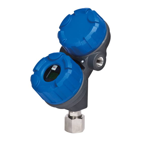
- Page 1 Enhanced Model 705 with fieldbus digital output ™ oundation 705 software v3.x fieldbus operating Manual ™ oundation uided Wave Radar Level Transmitter...
- Page 2 Safety Messages MAGNETROL will repair or replace the control at no The Eclipse system is designed for use in Category II, cost to the purchaser (or owner) other than transportation.
-
Page 3: Table Of Contents
fieldbus Enhanced Eclipse Model 705 OUND TION ™ Guided Wave Radar Transmitter Table of Contents 1.0 F fieldbus ™ Overview ........4 4.0 Function Blocks............20 OUND TION 1.1 Description ...............4 4.1 Overview..............20 4.1.1 Universal Fieldbus Block Parameters ....20 1.2 Benefits ..............5 4.2 Resource Block............21 1.3 Device Configuration..........5 4.3 Transducer Block.............24... -
Page 4: Overview
fieldbus ™ Overview OUNDATION Description fieldbus is a digital communications system ™ OUNDATION that serially interconnects devices in the field. A Fieldbus system is similar to a Distributed Control System (DCS) with two exceptions: • Although a F fieldbus system can use the same ™... -
Page 5: Benefits
™ OUNDATION interoperability by the Fieldbus Foundation. MAG- NETROL Enhanced Model 705 3X FF device registration information can be found at www.fieldbus.org. 2. Operation: With control now taking place within the devices in the field, better loop performance and control are the result. -
Page 6: Intrinsic Safety
Device Descriptions An important requirement of Fieldbus devices is the inter- operability concept mentioned earlier. Device Description (DD) technology is used to achieve this interoperability. The DD provides extended descriptions for each object and provides pertinent information needed by the host system. DDs are similar to the drivers that your personal computer (PC) uses to operate peripheral devices connected to it. -
Page 7: Link Active Scheduler (Las)
Link Active Scheduler (LAS) The default operating class of the Enhanced Eclipse Model 705 with F fieldbus is a basic device. However, it is ™ OUNDATION capable of being a Link Active Scheduler (LAS). The LAS controls all communication on a F fieldbus ™... -
Page 8: Quickstart Mounting
QuickStart Mounting NOTE: Confirm the configuration style and process connection ① size/type of the Eclipse transmitter. Ensure it matches the requirements of the installation before continuing with the QuickStart installation. ① Confirm the model and serial numbers on the nameplates of the Eclipse probe and transmitter are identical. -
Page 9: Quickstart Wiring
QuickStart Wiring WARNING! Explosion hazard. Do not connect or disconnect equip- ment unless power has been switched off or the area is known to be non-hazardous. NOTE: Ensure that the electrical wiring to the Eclipse transmitter is complete and in compliance with all regulations and codes. 1. -
Page 10: Quickstart Configuration
QuickStart Configuration The Eclipse transmitter comes partially configured from the factory but can be reconfigured in the shop (disregard fault message due to unattached probe). The minimum configuration instructions required in the field follow. 1. Power up the transmitter. The display changes every 5 seconds alternating between showing the Status, Level and Analog Input Block values. -
Page 11: Complete Installation
Model Number Serial Number Electrostatic Discharge (ESD) Handling Procedure MAGNETROL electronic instruments are manufactured to the highest quality standards. These instruments use elec- tronic components that may be damaged by static electricity present in most work environments. The following steps are recommended to reduce the risk of component failure due to electrostatic discharge. -
Page 12: Before You Begin
Before You Begin 3.3.1 Site Preparation Each Eclipse transmitter is built to match the specific physi- cal specifications of the required installation. Make sure the probe connection is correct for the threaded or flanged mounting on the vessel or tank where the transmitter will be placed. -
Page 13: Installing A Coaxial Probe
WARNING! The Model 7xD, 7xR or 7xT overfill probes should be used for Safety Shutdown/Overfill applications. All other Guided Wave Radar probes should be installed so the maximum overfill level is a minimum of 6" (150 mm) below the process connection. This may include utilizing a nozzle or spool piece to raise the probe. -
Page 14: Installing A Twin Rod Probe
3.4.2 installing a twin Rod Probe (Models 7xB, 7x5, and 7x7) Before installing, make sure the: • Model and serial numbers on the nameplates of the Eclipse probe and transmitter are identical. • Probe has adequate headroom for installation and has unob- structed entry to the bottom of the vessel. -
Page 15: To Install A Model 7X7 Standard Flexible Twin Rod Probe
3.4.2.2 To install a Model 7x7 standard flexible twin rod probe: ① Make sure the process connection is at least 2" NPT or a flanged mounting. ② Make sure that there is at least 1" (25 mm) spacing between ④⑤ ①... -
Page 16: Installing A Rigid Probe
2. Ratio of Diameter: Length (A:B) is 1:1 or greater; any ratio <1:1 (e.g., a 2"× 6" nozzle = 1:3) may require a Blocking Distance and/or DIELECTRIC adjustment (see Eclipse Installation & Operating Manual 57-600, Section 2.6.5.2, Measurement Type: Level and Volume). 3. -
Page 17: Installation Guidelines-Models 7X2/7X5 Bulk Solids Probes
③ Align the probe process connection with the threaded or ④ flanged mounting on the vessel. ① ④ For threaded connections, tighten the hex nut of the probe ② ③ process connection. For flanged connections, tighten flange bolts. ⑤ Probe can be shortened in field: a. -
Page 18: To Install A Bulk Solids Single Rod Probe
② Make sure that there is at least 1" (25 mm) spacing between the active probe rod and any part of the tank (walls, stillwell, pipes, support beams, mixer blades, etc.). Minimum stillwell diameter for Twin Rod probe is 3". ③... -
Page 19: Installing The Transmitter
3.4.5 installing the transmitter The transmitter can be ordered for installation as an Integral or Remote configuration. 3.4.5.1 Integral Mount ① Remove the protective plastic cap from the top of the probe. Put the cap in a safe place in case the transmitter has to be removed later. -
Page 20: Oundation
Function Blocks Overview The Enhanced Eclipse Model 705 Guided Wave Radar Level Transmitter operates on the principle of Time Domain Reflectometry (TDR). Refer to Bulletins 57-101 and 57-600 for more detailed information on the Eclipse product family. The Enhanced Eclipse Model 705FF is a Guided Wave Radar (GWR) level transmitter with seven F fieldbus ™... -
Page 21: Resource Block
(hardware) enabling jumper is present. Resource Block The RESOURCE block contains data specific to the Enhanced Model 705 transmitter, along with some information about the firmware. NOTE: The Resource Block has no control function. MODE_BLK: Must be in AUTO in order for the remain- ing blocks in the transmitter to operate. - Page 22 DD_REV: contains the revision of the DD associated with the version of firmware in the Enhanced Eclipse Model 705 transmitter. It is used by interface devices to correctly select the associated DD. RESTART: Default and Processor selections are available. Default will reset the Model 705 to the established block configuration.
- Page 23 FAULT_STATE, SET_FSTATE, CLR_FSTATE: these only apply to output function blocks. (The Model 705 has no output function blocks). MAX_NOTIFY: the maximum number of alert reports that the transmitter can send without getting a confirmation. The user can set the number low, to control alert flooding, by adjusting the LIM_NOTIFY parameter value.
-
Page 24: Transducer Block
Transducer Block The TRANSDUCER block is a custom block containing parameters that support the Enhanced Eclipse Model 705 level transmitter. It contains the GWR probe configuration, diagnostics, and calibration data, and outputs level with status information. The TRANSDUCER block parameters are grouped in a useful configuration. -
Page 25: Configuration Parameters
4.3.3 Eclipse Model 705 Configuration Parameters This set of parameters within the Transducer Block is impor- tant and required to configure every Eclipse Model 705 transmitter. PROBE_MODEL: Select the choice that corresponds to the first four digits of the model number of the probe. An “x” in the selection means that character is variable (the probe model number is shown on the nameplates attached to both the transmitter and probe). -
Page 26: Offset Description
4.3.4 offset description The parameter referred to as LEVEL_OFFSET in the Transducer Block is the desired level reading when liquid surface is at the end of the probe. The Eclipse transmitter is LCD Menu shipped from the factory with LEVEL_OFFSET set to 0. LvlUnits With this configuration, all measurements are referenced from the bottom of the probe. -
Page 27: Calibration Parameters
User-Calibration Parameters One of the main advantages of the Enhanced Eclipse Model 705 GWR transmitter is that the device does not need to be calibrated in the field. Every Enhanced Eclipse Model 705 transmitter is shipped precisely calibrated from the factory. On the other hand, part of the advantage of fieldbus is to provide the ability to monitor... -
Page 28: Firmware Version
4.4.2 Firmware Version The last parameter in the TRANSDUCER block gives the firmware version of the transmitter. FIRMWARE_VERSION: displays the version of the firmware. NOTE: The user should compare the DD file and revision number of the device with the HOST system to ensure they are at the same revision level. - Page 29 CHANNEL: The number of the logical hardware channel that is connected to this I/O block. This information defines the transducer to be used going to or from the physical world. L_TYPE: Determines if the values passed by the transducer block to the AI block may be used directly (Direct) or if the value is in different units and must be converted linearly (Indirect), or with square root (Ind Sqr Root), using the input range defined for the transducer and the associated...
-
Page 30: Local Display Of Analog Input
HI_ALM: Status for high alarm and associated time stamp. LO_ALM: Status for low alarm and associated time stamp. LO_LO_ALM: The status for low low alarm and its associated time stamp. The TRANSDUCER and AI block’s MODE_BLK parame- ter must be set to AUTO to pass the PV Value through the AI to the network. -
Page 31: Ai Out Display Screens
4.5.2 Local display of analog input transducer Block output These screens should only be considered as measured value indicators for configured transmitters. • The screens are not used for commissioning or diagnostic / troubleshooting purposes. • Prior to full fieldbus configuration (transmitter assigned a per- manent address, AI block(s) configured and scheduled for exe- cution, etc.), the value displayed will not reflect the transducer measurement. -
Page 32: Pid Block
PID block may reside in any device on the network. This includes a valve, a transmitter, or the host itself. The Enhanced Model 705 3X PID Block implementation fol- lows the specifications documented by the Fieldbus Foundation. 4.6.1 Pid Block Parameters ACK_OPTION: Used to set auto acknowledgement of alarms. - Page 33 4.6.1 Pid Block Parameters (cont.) DV_LO_LIM: The setting for the alarm limit used to detect the deviation low alarm condition. DV_LO_PRI: The priority of the deviation low alarm. FF_GAIN: The feedforward gain value. FF_SCALE: The high and low scale values associated with FF_VAL.
- Page 34 4.6.1 Pid Block Parameters (cont.) RATE: The derivative action time constant. RCAS_IN: Target setpoint and status that is provided by a supervisory host. RCAS_OUT: Block setpoint and status that is provided to a supervisory host. RESET: The integral action time constant. ROUT_IN: Block output that is provided by a supervisory host.
-
Page 35: Model 705 Found Tion Fieldbus ™ Menu
Model 705 Menu: Step by Step Procedures The following table describes the software menu displayed by the Eclipse F fieldbus transmitter for “Level ™ OUNDATION Only” measurement. Use this table as a step by step guide to configure the transmitter. The second column presents the menus shown on the trans- mitter display. - Page 36 display Password action Comment SZHeight Enter distance below BlockDis where xx.x su 5.1 to 2286 cm (2 to 900 in) User SZ Fault will be asserted SZ Latch Reset Press Enter to clear a Safety Zone latch User Threshld (select) For interface, refers to threshold for Select from CFD, Fixed User...
- Page 37 display Password action Comment Neg Ampl Superuser parameter Diagnostic parameter Superuser Pos Ampl Superuser parameter Diagnostic parameter Superuser Signal Indication of level Diagnostic Display None signal amplitude Compsate Select from None, Superuser Parameter Superuser Manual, Auto DrateFct xxxx Compsate = Auto, velocity Diagnostic Display None derating factor...
-
Page 38: Diagnostic Parameters
The LIMIT attribute is the same as the last good measurement. When the Enhanced Model 705 detects a level above the highest measurement point of the probe the operational mode is shown as “May Be Flooded.” This is due to the fact that, since the actual level location above the top of some probes is not known, the output may not be accurate. -
Page 39: Simulation Feature
If the Model 705 fails to find a measurable level, either due to an actual loss of a level signal or the loss of a proper Fiducial (reference) signal, the TRANSDUCER BLOCK maintains the last good value as the output and flags the fail- ure. -
Page 40: Reference Information
Reference Information Troubleshooting The Eclipse transmitter is designed and engineered for WARNING! trouble-free operation over a wide range of operating Explosion hazard. Do not connect or conditions. Common transmitter problems are discussed disconnect equipment unless power in terms of their symptoms and recommended corrective has been switched off or the area is actions. -
Page 41: Status Messages
7.1.2 device Status Parameter in the transducer Block The following table lists the conditions indicated in the Device Status parameter. It also shows the affect the condition has on PV status, Sub-Status and Limit, XD ERROR and BLOCK ALARM are not affected by these conditions directly. device Status PV Status PV Sub Status... - Page 42 7.1.2 device Status Parameter in the transducer Block The next set of conditions is the device warnings. The con- dition will not jeopardize the level measurement. However, knowledge of the condition may be useful in troubleshooting the device. The following table describes the conditions that can be seen in Device Status: display Message action...
-
Page 43: Ff Segment Checklist
7.1.3 FF Segment Checklist There can be several reasons for a F fieldbus ™ OUNDATION installation to be in a faulty condition. In order to ensure that communication can be established, the following requirements must be met. • Device supply voltage must be higher than 9 VDC with a maximum of 32 VDC. -
Page 44: Agency Approvals
Agency Approvals aGEnCY ModEL aPPRoVEd aPPRoVaL CatEGoRY aPPRoVaL CLaSSES 705-52XX-1XX Intrinsically Safe Class , Div. 1; Groups A, B, C, & D 705-52XX-2XX Class , Div. 1; Groups E, F, & G T4 Class , Type 4X IP66 Entity/FISCO Explosion Proof ➀ 705-52XX-3XX Class , Div. -
Page 45: Agency Specifications
7.2.1 agency Specifications – F fieldbus System ™ oundation 57-640 Eclipse Guided Wave Radar Transmitter - F fieldbus OUNDATION... -
Page 46: Specifications
Specifications 7.3.1 Functional System design Measurement Principle Guided time-of-flight via time domain reflectometry input Measured Variable Level, determined by the time-of-flight of a guided radar pulse from transmitter to product surface and back Zero and Span 6 inches to 75 feet (15 to 2286 cm) user interface Keypad 3-button menu-driven data entry and system security... -
Page 47: Performance - Model 705
7.3.2 Performance - Model 705 Reference Conditions ➀ Reflection from water at +70 °F (+20 °C) with 72" coaxial probe (CFD threshold) Linearity ➁ Coaxial/Twin Rod Probes: <0.1% of probe length or 0.1 inch (whichever is greater) Single Rod Probes: <0.3% of probe length or 0.3 inch (whichever is greater) Measured Error ¬... -
Page 48: Parts
Parts 7.4.1 Replacement Parts item description Part number ① Electronic module fieldbus ™ with display Z031-2841-001 OUNDATION fieldbus ™ without display Z031-2841-002 OUNDATION ② Terminal board fieldbus ™ Explosion Proof Z030-9151-003 OUNDATION FISCO Z030-9151-004 ③ O-ring (Viton) 012-2201-237 (Consult Factory for alternative O-ring materials) ④... -
Page 49: Model Numbers
Model Numbers 7.5.1 transmitter BaSiC ModEL nuMBER Eclipse Guided Wave Radar Level Transmitter PowER 24 VDC, Two-wire SiGnaL outPut 4-20 mA with HART fieldbus ™ Digital Communications (English only) OUNDATION PROFIBUS PA ™ Digital Communications (English only) oPtionS None aCCESSoRiES No digital display and keypad Digital display and keypad MountinG/CLaSSiFiCation... -
Page 50: Probe
7.5.2 Probe BaSiC ModEL nuMBER Eclipse GWR probe, English unit of measure Eclipse GWR probe, Metric unit of measure ConFiGuRation/StYLE Coaxial Standard Coaxial High Temp./High Pressure ⁄ " process connection Dielectric range ≥1.4 or larger Coaxial High Pressure Coaxial Overfill Coaxial Hot Water/Steam 2"... - Page 51 7.5.2 Probe insertion Length insertion Length insertion Length insertion Length nPt Process Connection BSP Process Connection anSi or din welded Flange Hygienic Flange PRoCESS ConnECtion SizE/tYPE tHREadEd ConnECtionS " NPT Thread ➀ ⁄ 1" BSP Thread ➀ 2" NPT Thread ¬ 2"...
- Page 52 7.5.2 Probe HYGiEniC FLanGE ConnECtionS ⁄ " Tri-clover ® type, 16 AMP Hygienic Flange 1" or 1 ⁄ " Tri-clover type, 16 AMP Hygienic Flange 2" Tri-clover type, 16 AMP Hygienic Flange 3" Tri-clover type, 16 AMP Hygienic Flange 4" Tri-clover type, 16 AMP Hygienic Flange ⁄...
-
Page 53: References
STEAM_CAL_MOUNT Steam Cal Mount STRAPPING_TABLE_POINT04 StrapTbl Pt04 NON_VOL_STAT Non Vol Stat StrapTbl Pt05 DATE_CODE Date Code STRAPPING_TABLE_POINT05 StrapTbl Pt06 Magnetrol S/N STRAPPING_TABLE_POINT06 MAGNETROL_SERIAL_NUMBER STRAPPING_TABLE_POINT07 StrapTbl Pt07 FIRMWARE_VERSION Firmware Ver 57-640 Eclipse Guided Wave Radar Transmitter - F fieldbus ™ OUNDATION... -
Page 54: Configuration Data Sheet
Enhanced Model 705 Eclipse Guided Wave Radar Transmitter fieldbus Configuration Data Sheet ™ OUNDATION Copy blank page and store calibration data for future reference and troubleshooting. Item Value Value Value Vessel Name Vessel # Process Medium Tag # Electronics Serial #... - Page 55 Enhanced Model 705 Eclipse Guided Wave Radar Transmitter fieldbus Configuration Data Sheet ™ OUNDATION Copy blank page and store calibration data for future reference and troubleshooting. Item Value Value Value TROUBLESHOOTING Working Value Non-Working Value FidTicks FidSprd Fid Type HF Cable...
- Page 56 US 6,588,272; US 6,626,038; US 6,640,629; US 6,642,807; US 6,690,320; US 6,750,808; US 6,801,157. May depend on model. 705 Enterprise Street • Aurora, Illinois 60504-8149 • 630-969-4000 • Fax 630-969-9489 info@magnetrol.com • www.magnetrol.com Copyright © 2016 Magnetrol International, Incorporated. All rights reserved. Printed in the USA. fieldbus logo is a registered trademark of the Fieldbus Foundation OUNDATION BuLLEtin: 57-640.5...
Need help?
Do you have a question about the Enhanced Model 705 and is the answer not in the manual?
Questions and answers