Magnetrol Eclipse 705 Safety Manual
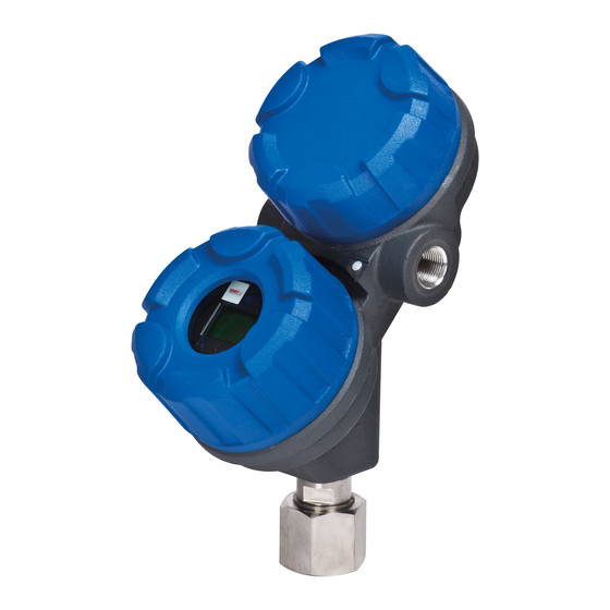
Eclipse enhanced model 705 guided wave radar level transmitter
Hide thumbs
Also See for Eclipse 705:
- Installation and operating manual (68 pages) ,
- Operating manual (52 pages) ,
- Functional safety manual (16 pages)
Table of Contents
Advertisement
Quick Links
Functional Safety Manual
SIL Certified Safety Manual for
Enhanced Model 705-51AX-XXX
Guided Wave Radar
Level Transmitter
This manual complements and is intended to be used with the
Eclipse
®
Enhanced Model 705 Installation and Operating manual
(Bulletin 57-600 dated August 2005 or later).
Safety Function
The HART
®
version of the Eclipse
Guided Wave Radar (GWR) transmitter will measure
level and transmit a signal proportional to that level
within the stated safety accuracy of ±2% of span or the
measured error published in I/O Manual 57-600,
whichever is greater. In addition, when continuous,
automatic diagnostics detect that the transmitter cannot
perform this function, the output will be driven to the
customer-specified out-of-range signal (i.e., less than
3.8 mA or greater than 20.5 mA).
The Enhanced Model 705 is certified for use in low or
high demand level measurement applications.
pplication
The Enhanced Model 705 Guided Wave Radar level
transmitter can be applied in most process or storage
vessels, bridles, and bypass chambers up to the probe's
rated temperature and pressure. The Enhanced Model 705
can be used in liquids, slurries or solids to meet the safe-
ty system requirements of IEC 61508/IEC 61511-1.
Benefits
• Level protection to SIL 3 as certified by exida
Certification per IEC 61508/IEC 61511-1.
• Probe designs to +800 °F (+427 °C),
6250 psig (430 bar) and full vacuum
• Cryogenic applications to -320 °F (-190 °C)
• IS, XP and Non-Incendive approvals
• Ability to measure reliably to the very top of the vessel.
(Meets TÜV: WHG 19 overfill specifications when
used with Model 7xD, 7xG, 7xR, and 7xT probes).
Software v3.x
®
Enhanced Model 705
Advertisement
Table of Contents

Related Manuals for Magnetrol Eclipse 705


Summary of Contents for Magnetrol Eclipse 705
- Page 1 SIL Certified Safety Manual for Enhanced Model 705-51AX-XXX Software v3.x Functional Safety Manual Guided Wave Radar Level Transmitter This manual complements and is intended to be used with the Eclipse ® Enhanced Model 705 Installation and Operating manual (Bulletin 57-600 dated August 2005 or later). Safety Function The HART ®...
-
Page 2: Table Of Contents
Eclipse Enhanced Model 705 Guided Wave Radar Level Transmitter ® SIL Certified Safety Manual for Enhanced Model 705-51 X-XXX Table of Contents 1.0 Introduction ..............3 5.6 Configuration ............7 1.1 Theory of Operation..........3 5.6.1 General............7 1.2 Product Description ..........3 5.6.2 SIS Configuration Requirements....8 1.3 Determining Safety Integrity Level (SIL) ....3 5.6.3 Write Protecting /Locking ......8 2.0 Level Measuring System ..........4... -
Page 3: Introduction
Introduction Theory of Operation Guided Wave Radar is based upon the principle of TDR (Time Domain Reflectometry). TDR utilizes high frequency pulses of electromagnetic energy transmitted down a probe. When a pulse reaches a surface that has a higher dielectric than the air/vapor in which it is traveling, the pulse is reflected. -
Page 4: Level Measuring System
4–20mA range: ±2% of span or the measured error published in I/O Manual 57- 600, Figure 1 whichever is greater. MAGNETROL defines a safe failure Typical System as one in which the 4–20 mA current is driven out of range (i.e., less than 3.8 mA or greater than 20.5 mA). -
Page 5: Miscellaneous Electrical Considerations
Miscellaneous Electrical Considerations The following are miscellaneous electrical items that must be considered in any installation: 2.2.1 Pollution Degree 2 The Enhanced ECLIPSE Model 705 is designed for use in Category II, Pollution Degree 2 installations. The usual pollution degree used for equipment being evalu- ated to IEC/EN 61010 is a nonconductive pollution of the sort where occasionally a temporary conductivity caused by condensation is expected. -
Page 6: Instructions
Instructions Systematic Limitations The following must be observed to avoid systematic failures: 5.1.1 Application As the probe configuration establishes the fundamental per- formance characteristics of the system, choosing the proper Guided Wave Radar probe is the most important decision in the specification/application process. Coaxial, twin ele- ment (rod or cable), and single element (rod or cable) are the three basic GWR probe configurations. -
Page 7: Storage
Refer to section 8.3 for Safety System Assumptions (SSA). Configuration 5.6.1 General The MAGNETROL Model 705 can be configured via the local LCD/keypad, a HART compatible handheld terminal or with a personal computer containing the proper HART DTM and framework program such as PACTw re ™... -
Page 8: Sis Configuration Requirements
5.6.2 SIS Configuration Requirements Ensure the GWR transmitter parameters have been properly configured for the specific application and probe. Special consideration should be given to the following con- figuration parameters: F ULT: O NOT choose HOLD for this parameter as a Fault will not be annunciated on the current loop. -
Page 9: Site Acceptance Testing
Refer to section 2.6.4 of the Enhanced ECLIPSE Model 705 Installation and Operating Manual 57-600 for additional information regarding password protection. Ensure that an exclamation mark (!) appears as the last char- acter on the first line of the LCD to confirm the present password has been accepted. -
Page 10: Troubleshooting
• As there are no moving parts in this device, the only main- tenance required is the proof test shown in Section 6.1.4. • Firmware can only be upgraded by factory-trained personnel. • Report all Faults to MAGNETROL technical support. Recurrent Function Tests Proof Testing 6.1.1 Introduction... -
Page 11: Proof Test Procedure
8. If the calibration is off by more than 2%, contact MAGNETROL Technical Support for assistance. 9. If the calibration is within tolerance, the proof test is com- plete. Proceed to step 10. -
Page 12: Report Lifetime Of Critical Components
Report Lifetime of Critical Components Although a constant failure rate is assumed by the proba- bilistic estimation method, this only applies if the useful lifetime of components is not exceeded. Beyond the useful lifetime of a component, the result of the probabilistic calculation method is meaningless, as the probability of failure significantly increases with time. -
Page 13: Ppendices
Safety Integrity Function, SIF. MAGNETROL cannot directly control the user life cycle of a SIF using this product but needs to have assumptions on how the product will be used. -
Page 14: Fmeda Report: Exida Management Summary
FMED Report: exida Management Summary 57-651 Eclipse ® SIL Certified Safety Manual for Enhanced Model 705-51 X-XXX... - Page 15 57-651 Eclipse ® SIL Certified Safety Manual for Enhanced Model 705-51 X-XXX...
- Page 16 • IEC 61508-2: 2010-04 • IEC 61508-3: 2010-04 Disclaimer MAGNETROL accepts no liability whatsoever for the use of these numbers or for the correctness of the standards on which the general calculation methods are based. ASSURED QUALITY & SERVICE COST LESS...
Need help?
Do you have a question about the Eclipse 705 and is the answer not in the manual?
Questions and answers