Table of Contents
Advertisement
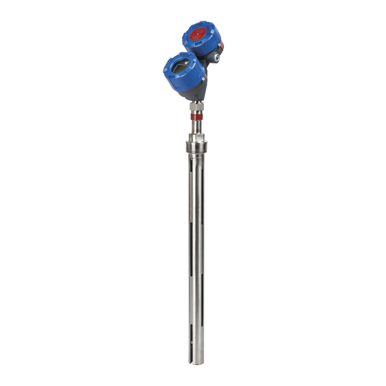
SIL Certified Safety Manual for
Eclipse
Model 706-512X-XXX
®
High Performance uided Wave
Radar Level Transmitter
This manual complements and is intended to be used with the
Magnetrol
Eclipse
Model 706 High Performance Guided Wave
®
®
Radar Installation and Operating manual ( ulletin 57- 606).
Safety Function
The HART
version of the Eclipse
®
Guided Wave Radar (GWR) transmitter will measure
level and transmit a signal proportional to that level
within the stated safety accuracy of ±2% of span (or the
measured error published in I/O Manual 57- 606,
whichever is greater). In addition, when continuous,
automatic diagnostics detect that the transmitter cannot
perform this function, the output will be driven to the
customer-specified out-of-range signal (i.e., 3.6 mA or
21 mA).
The Enhanced Model 706 is certified for use in low
demand level measurement applications.
pplication
The HART
version of the ECLIPSE Model 706
®
Guided Wave Radar level transmitter can be applied in
most process or storage vessels, bridles, and bypass
chambers up to the probe's rated temperature and pres-
sure. It can be used in liquids, slurries, or solids with a
dielectric constant in the range 1.4–100 to meet the
safety system requirements of IEC 61508 (Edition 2.0,
2010) and IEC 61511-1.
Benefits
• Level protection to SIL 3 as certified by exida
Certification per IEC 61508/IEC 61511-1.
• Probe designs to +850 °F (+454 °C), 6250 psig
(430 bar) and full vacuum.
• Cryogenic applications to -320 °F (-190 °C).
• Intrinsically safe, Explosion-proof and Non-Incendive
approvals.
• Quick connect/disconnect probe coupling.
Enhanced Model 706
®
Advertisement
Table of Contents

Related Manuals for Magnetrol Eclipse 706-512


Summary of Contents for Magnetrol Eclipse 706-512
- Page 1 Model 706-512X-XXX ® High Performance uided Wave Radar Level Transmitter This manual complements and is intended to be used with the Magnetrol Eclipse Model 706 High Performance Guided Wave ® ® Radar Installation and Operating manual ( ulletin 57- 606).
-
Page 2: Table Of Contents
Eclipse Model 706 High Performance Guided Wave Radar Level Transmitter ® SIL Safety Manual for Eclipse Model 706-512x-xxx ® Table of Contents 1.0 Introduction ..............3 7.0 Recurrent Function Tests ..........9 1.1 Product Description ..........3 7.1 Proof Testing .............9 1.2 Theory of Operation..........3 7.1.1 Introduction...........9 1.3 Determining Safety Integrity Level (SIL) ....3 7.1.2 Interval............9... -
Page 3: Introduction
Introduction Product Description The ECLIPSE Model 706 High Performance Guided Wave Radar Level Transmitter is a two-wire, loop-powered Table 1 24 VDC level transmitter based on Guided Wave Radar Enhanced ECLIPSE Model Numbers (GWR) technology. Transmitters: NOTE: For Safety Instrumented Systems usage, it is assumed that the Model 706, 706-512*-*** (HART) 4–20 mA output is used as the safety variable. -
Page 4: Pplicable Models
• The only unsafe mode is when the unit is reading an incorrect level within the 4–20 mA range (> ±2% deviation). • MAGNETROL defines the faulted mode as one in which the 4–20 mA current is driven out of range (i.e., less than 3.8 mA or greater than 21.5 mA). -
Page 5: Miscellaneous Electrical Considerations
Miscellaneous Electrical Considerations Following are miscellaneous electrical issues to be considered in a safety system. 3.1.1 Pollution Degree 2 The ECLIPSE Model 706 transmitter is designed for use in a Category II, Pollution Degree 2 installation, which is defined by a nonconductive pollution of the sort where occasionally a temporary conductivity caused by condensation must be expected. -
Page 6: Environmental
Coaxial, twin flexible cable, and single element (rod or cable) are the three basic configurations. As the probe configuration establishes fundamental performance characteristics, the probe for use with the ECLIPSE Model 706 transmitter should be selected as appropriate for the application. The Model 706 is designed for use in many applications in process industries. -
Page 7: Necessary Tools
Necessary Tools Following are the necessary tools needed to carry out the prescribed procedures: • Open-wrenches or adjustable wrench to fit the process connection size and type. • Coaxial probe: 1 ⁄ " (38mm) • Twin Rod and Single rod probes: 1 ⁄... -
Page 8: Site Acceptance Testing
C) Safety Function Response Time: 3 seconds (with Damping=0) 6.8.2 Troubleshooting Report all failures to the MAGNETROL Technical Support Department. Refer to the Model 706 Installation and Operating Manual Bulletin 57-606 for troubleshooting device errors. 57-657 SIL Certified Safety Manual for ECLIPSE Model 706... -
Page 9: Model 706-512X-Xxx
• As there are no moving parts in this device, the only main- tenance required is the SIL Proof Test. • Firmware can only be upgraded by factory personnel. Recurrent Function Tests Proof Testing 7.1.1 Introduction Following is the procedure utilized to detect Dangerous Undetected (DU) failures. - Page 10 Step Action Use the DIAGNOSTICS menu to perform a “CURRENT LOOP TEST”. Select DIAGNOSTICS / ADVANCED DIAGNOSTICS / TRANSMITTER TESTS / Analog Output Test to change the output loop current and confirm the actual current matches the value chosen. a.) Send a HART command to the transmitter (or use the local interface) to go to the high alarm current output, 22 mA, and verify that the analog current reaches the valve.
-
Page 11: Safety Requirements
Safety Integrity Function, SIF. Magnetrol cannot directly control the user life cycle of a SIF using this product but needs to have assumptions on how the product will be used. -
Page 12: Safety Function Requirements
Safety Function Requirements This section lists the Safety Function Requirements that specify what safety relevant functionality is to be performed for implementation of the safety integrity function and also to maintain the desired level of safety integrity. These requirements may also rule out particular functionality for SIF usage that could lead to designs that are difficult to vali- date for deterministic performance or safety integrity. -
Page 13: Ppendices
ppendices SIL Certificate 57-657 SIL ertified Safety Manual for E LIPSE Model 706... -
Page 14: Fmeda Report: Exida Management Summary
FMED Report: exida Management Summary 57-657 SIL ertified Safety Manual for E LIPSE Model 706... -
Page 15: Specific Model 706 Values
Specific Model 706 Values ECLIPSE Product Model 706-512x-xxx SIL 2 93.1% PFD avg Refer to FMEDA report Report: Lifetime of Critical Components According to section 7.4.9.5 of IEC 61508-2, a useful life- time, based on experience, should be assumed. Although a constant failure rate is assumed by probabilistic estimation method, this only applies provided that the useful lifetime of components is not exceeded. - Page 16 84.00.01-2004” isclaimer The SIL values in this document are based on an FMEDA analysis using exida’s SILVER Tool. MAGNETROL accepts no liability whatsoever for the use of these numbers or for the correctness of the standards on which the general calculation methods are based.
Need help?
Do you have a question about the Eclipse 706-512 and is the answer not in the manual?
Questions and answers