Fujitsu DL7600 Maintenance Manual
Hide thumbs
Also See for DL7600:
- User manual (285 pages) ,
- Brochure & specs (2 pages) ,
- Maintenance manual (169 pages)
Table of Contents
Advertisement
Quick Links
Download this manual
See also:
User Manual
Advertisement
Table of Contents

Related Manuals for Fujitsu DL7600


Summary of Contents for Fujitsu DL7600
-
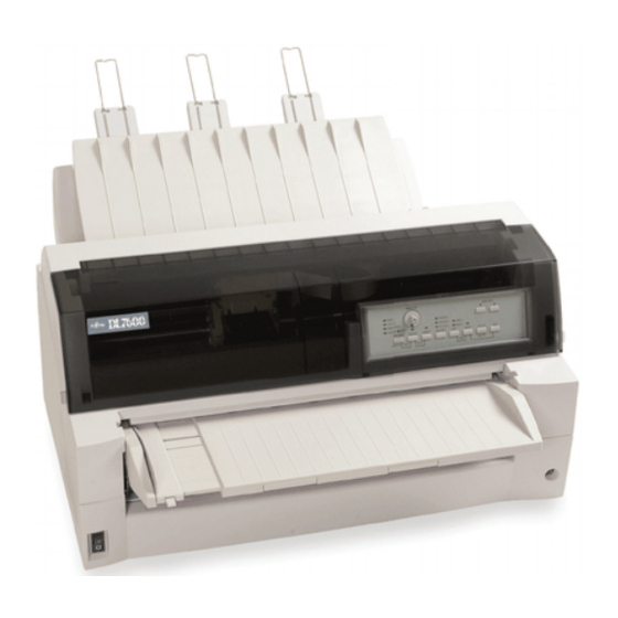
Page 1: Maintenance Manual
DL7600 DOT MATRIX PRINTER MAINTENANCE MANUAL FUJITSU ISOTEC LIMITED... - Page 2 Procedure of replacing SP Motor ASY is amended. Specification No. C147-F052-04EN The contents of this manual may be revised without prior notice. All Rights Reserved, Copyright © 2008 FUJITSU ISOTEC LIMITED. No part of this manual may be reproduced in any form without permission.
- Page 3 Hayes Park Central, Phone: (886-2) 2311-2255 Hayes End Road, Fax: (886-2) 2311-2277 Hayes, Middlesex UB4 8FE, U.K. FUJITSU SYSTEMS BUSINESS (THAILAND) LTD. Phone:(44-20) 8573-4444 Exchange Tower, 22nd-23rd Fl, 388 Sukhumvit Road, Fax:(44-20) 8573-2643 Kwaeng Klongtoey, Khet Klongtoey, Bangkok 10110, Thailand...
- Page 4 PREFACE This manual is for engineers who operate, install, or maintain the DL7600 printer, and covers: Chapter 1: Printer specifications, performance, and configuration Chapter 2: Unpacking, performance check, and connection Chapter 3: Troubleshooting Chapter 4: Maintenance Chapter 5: Principles of operation...
-
Page 5: Table Of Contents
CONTENTS CONTENTS ............................... 5 CHAPTER 1 PRINTER SPECIFICATIONS, PERFORMANCE, AND CONFIGURATION .... 9 1.1 Overview ............................9 1.2 Equipment Structure ......................... 9 1.2.1 Overview ............................ 9 1.2.2 Model configuration ........................9 1.2.3 Structure ........................... 10 (1)Exterior components ......................... 12 (2)Printing mechanism ........................15 (3) Lower cover .......................... - Page 6 4.4 Maintenance levels ......................... 40 4.5 Preventive Maintenance ......................... 40 4.6 Part Drawings ..........................40 4.7 Parts That must not be Disassembled ................... 41 4.8 Level 1 Maintenance ........................42 4.9 Level 2 maintenance ........................43 4.9.1 Parts replacement ........................43 (1) Tractor Unit replacement......................
- Page 7 (35) SP FAN UNIT replacement ....................88 (36) INLK SW UNIT replacement ....................89 (37) PS PCA replacement ......................90 (38) HCPP switch ASY replacement ..................... 91 (39) Sensor cover TR/TR PES ASY replacement ................. 92 (40) Card Guide ASY replacement ....................93 (41) TOF S.
- Page 8 CHAPTER 5 PRINCIPLES OF OPERATION ................. 138 5.1 Overview ............................138 5.2 Mechanical Operation ........................139 5.2.1 Printing Operation ........................139 5.2.1.1 Print head ........................139 5.2.1.2 Spacing operation ......................140 5.2.1.3 LRES (Carriage position) detection ................141 5.2.1.4 Ribbon feed mechanism ....................142 5.2.1.5 Automatic paper thickness control mechanism ...............
-
Page 9: Chapter 1 Printer Specifications, Performance, And Configuration
PERFORMANCE, AND CONFIGURATION 1.1 Overview This manual is for maintenance engineers, and covers overall DL7600 printer maintenance, together with detailed information such as troubleshooting and component replacement. The maintenance manual is described by the premise that understands the user's manual. -
Page 10: Structure
APTCHP SW RF motor Reactor HCPP motor AC SWITCH assembly Connector Board HCPPHP SW AC INLET assembly PS Sensors Nip Roller assembly FTRPE Sensors Dv Roller assembly RTRPE Sensors Lower cover assembly Platen Roller assembly Figure 1.1 Structure of DL7600... - Page 11 Connector board FTRPE sensor sensors Motor Motor INTER LOCK Motor Motor Motor 4 Motor 2 Motor 3 Motor 1 Option board RS232C or USB ROM Board Centro Power supply Control Panel F CSF inlet connector Figure 1.2 Block Diagram of DL7600...
-
Page 12: Exterior Components
This section gives information on exterior components of the printer: covers, removable mechanism units,etc. Front cover Ribbon cassette Print head Control panel Upper cover Power switch Interface connector Soundproof cover Tractor unit Front CSF connector Rear CSF connector Rear stacker Power connector Figure 1.3 Exterior components of DL7600... - Page 13 USB Connector The ferrite core that Comes with the LAN Card must be attached. Figure 1.4 Interface type of DL7600 b. Upper cover The bottom cover and the upper cover are fixed with a back screw. b. Front cover The front cover is opened to replace the ribbon cartridge.
- Page 14 The LEDs indicate printer basic statuses and paper feed path conditions. LCD displays the state of the printer. The buzzer sounds to indicate certain operating and printer statuses. [LED type] [LCD type] Figure 1.5 Control panel of DL7600...
-
Page 15: Printing Mechanism
(2)Printing mechanism Ribbon cartridge Carriage Stay shaft Stepping motor for Carriage drive mechanism Print head HCPP motor APTC mechanism Paper feed mechanism HCPP mechanism Figure 1.6 Mechanism of DL7600... - Page 16 The printing mechanism fit into the bottom cover. And Upper Cover holds it in position. a. Carriage The carriage supports the removable 24-wire print head, and slides left and right on the stay shaft. The ribbon feed gear system moves the ribbon in one direction regardless of carriage movement. It has four sensors: LRES, TOFL, TOFR and APTC sensor.
-
Page 17: Lower Cover
(only 200v) CSF connector AC inlet Lower cover Figure 1.7 Electric components of DL7600 a. Lower cover The Lower cover supports the printer mechanism and electric units as follows. b. ROM board (control board with flash ROM) The ROM board controls the host interface, control panel, and printing mechanism using an MPU and an LSI circuit. -
Page 18: Option And Consumables
Cut-sheet feeders A cut-sheet feeder allows both single-part cut sheets and multi-part cut sheets to be fed automatically. The SF94 single-bin feeder is available for DL7600. b. Tractor unit An additional tractor unit can be installed in the printer. Because the standard tractor unit is installed at the front of the printer at shipment, the additional tractor is installed at the rear of the printer. -
Page 19: Chapter 2 Unpacking, Performance Check, And Connection
CHAPTER 2 UNPACKING, PERFORMANCE CHECK, AND CONNECTION 2.1 Overview The DL7600 printer comes packed for transportation. After unpacking and before installation, the printer must undergo self-test printing. Installation requires minimum time and expense. 2.2 Notes on Installation For best results, note the following points when installing the paper: ・Place the printer on a level, vibration-free surface. -
Page 20: Unpacking
2.3 Unpacking Unpacking the printer as follows(Figure 2.1) 1. Open the carton and remove Ribbon cartridge and Cushion L/R. 2. Lift up the printer using the grip at right and left of the printer. 3. Take out accessories (Power cord, Manual). Figure 2.1 Unpacking the printer and accessories... - Page 21 4.Open the front cover and remove the cardboard shipping restraint holding the carriage in place Figure 2.2 Removing the shipping materials 6.Store the original shipping carton and packing materials for future use in moving or shipping the printer.
-
Page 22: Inspection After Unpacking
2.4 Inspection after Unpacking 1. Carefully check assemblies and accessories for visible damage. 2. Install the ribbon cartridge. See the User’s Manual for details. 3. Check the rated voltage or the printer and AC power outlet, then connect the AC power cord between the printer and AC power outlet. -
Page 23: Chapter 3 Troubleshooting
Section 3.2 explains error displays on the control panel that help clarify the cause of a problem. Section 3.3 explains the self-correction functions of the DL7600 printer. For replacement and adjustment after recovery, see Chapter 4. -
Page 24: Problems At Power-On Initialization (Part 002/4)
3.1.1 Problems at power-on initialization (part 002/4) Symptom Cause Response 3 The POWER lamp is After the POWER lamp goes The control board Is Replace and initialize on, simultaneous blinking of defective. the control board. all other lamps is not performed. -
Page 25: Problems At Power-On Initialization (Part 003/4)
3.1.1 Problems at power-on initialization (part 003/4) Symptom Cause Response 4 [LED type] ROM/RAM alarm Mismatch of ROM is • Download correct The PAPER OUT lamp [LED type] detected. program to the flash blinks. Also HI IMPACT and ROM. TRACTOR F lamps blink. •... -
Page 26: Problems At Power-On Initialization (Part 004/4)
3.1.1 Problems at power-on initialization (part 004/4) Symptom Cause Response 4 [LED type] FAN alarm FAN motor alarm is The PAPER OUT lamp [LED type] detected. blinks. Also REMOVE PAPER and CUT A. The FAN motor A. Connect the SHEET lamps blink. connector is Connector correctly. -
Page 27: Problems Related To Printing (Part 001/2)
3.1.2 Problems related to printing (part 001/2) Symptom Cause Response 1 The POWER lamp +40 V over voltage alarm The power supply is Replace the power goes off during faulty.( The power supply unit. printing. supply is a high Then, turn the power voltage.) switch OFF, and turn on the power after 10... -
Page 28: Problems Related To Printing(Part 002/2)
3.1.2 Problems related to printing(part 002/2) Symptom Cause Response 4 Data sent from the host Printing operation is not The interface cable is Connect the interface is not printed at all. performed at all. not connected cable properly. Data cannot be properly. -
Page 29: Problems Related To Printing Result
3.1.3 Problems related to printing result Symptom Cause Response 1 The data sent from the Self-test printing is performed The setup mode Enter setup mode and host does not match the normally. setting is invalid. change the mode setting print results. properly. -
Page 30: Problems Related To Print Quality (Part 001/2)
3.1.4 Problems related to print quality (part 001/2) Symptom Cause Response 1 A dot is missing or an excess dot is printed. The print head is Replace the print head. (See other items about blurring of the top or bottom defective. -
Page 31: Problems Related To Print Quality (Part 002/2)
3.1.4 Problems related to print quality (part 002/2) Symptom Cause Response 5 Printing is partly blank or the ribbon is out of place. • The manual paper • Adjust the manual paper thickness adjustment thickness adjustment dial The ribbon is loose. dial is set improperly. -
Page 32: Problems Related To Paper Feed (Part 001/2)
3.1.5 Problems related to paper feed (part 001/2) Symptom Cause Response 1 Paper selection cannot be performed properly. • The paper selection HCPP • Replace the HCPP motor does not work motor. • HCPPSW ASY is • Replace the HCPPSW defective. -
Page 33: Problems Related To Paper Feed (Part 002/2)
3.1.5 Problems related to paper feed (part 002/2) Symptom Cause Response 9 Paper skews or a paper jam occurs. • Paper is set improperly. • Set paper properly. • Paper is defective. • Replace paper • The manual paper (with that conforming to thickness the media specifications) adjustment dial is set... -
Page 34: Problems Related To The Control Panel
3.1.6 Problems related to the control panel Symptom Cause Response 1 Switches on the control panel are disabled. • The printer is online. • Turn the printer offline. • The connection between • Connect the cable the control panel board properly, or replace the and control board is cable. -
Page 35: Error Display
3.2 Error Display This printer indicates errors on the control panel. There are three groups of errors as explained below. (1) Warning errors The buzzer sounds and the ONLINE indicator still lights. For a data transmission error in the interface, only the buzzer indicates the error. The printer continues printing unless placed offline or other groups of errors occur. -
Page 36: Operational Errors
(2) Operational errors [LED type] The PAPER OUT indicator is lighted. The buzzer sounds, the PAPER OUT indicator lights up, and the printer is placed offline when operation is required. [LCD type] The error message is displayed with LCD. The buzzer sounds, display the error name by the LCD display, and the printer is placed offline when operation is required. - Page 37 [LED type] The PAPER OUT lamp blinks with other lamps. For a circuit malfunction detected in the printer: • The printer stops printing immediately. • The ONLINE indicator turns off. • All buttons of the control panel are invalid. Table 3.4 Fatal alarms displayed on control panel Lamp Condition of occurrence Alarm name...
- Page 38 [LCD type] The error message is displayed with LCD. For a circuit malfunction detected in the printer: • The printer stops printing immediately. • The ONLINE indicator turns off. • All buttons of the control panel are invalid. Table 3.5 Fatal alarms displayed on control panel Alarm name Condition of occurrence ...
-
Page 39: Chapter 4 Maintenance
This chapter explains the maintenance levels 1 and 2 for cleaning, lubrication, inspection, and adjustment of the DL7600 printer 4.1 Overview Designed using the latest technology, the DL7600 printer offers high reliability and easy maintenance. Parts requiring lubrication and adjustment have been reduced and the replacement of defective parts made easier than previous models. -
Page 40: Maintenance Levels
4.4 Maintenance levels Maintenance for the DL7600 printer is done at two levels. Level 1 maintenance includes cleaning and lubrication. Level 2 maintenance includes level 1 items, plus replacement of PC boards, units, and mechanical subassemblies, and adjustment after replacement. -
Page 41: Parts That Must Not Be Disassembled
4.7 Parts That must not be Disassembled This section gives the locations of parts that must not be disassembled. Table 4.2 lists components not to be disassembled and whose mounting screws are not to be loosened or removed. Parts not to be Disassembled Components Parts Remark... -
Page 42: Level 1 Maintenance
Level 1 maintenance includes only cleaning and lubrication. These can be performed without removing covers although Figure 4.3 shows the printer with the covers removed. Check the DL7600 printer inside for paper particles, dust, and dirt, and remove these as explained below. After cleaning, lubricate moving parts. -
Page 43: Level 2 Maintenance
4.9 Level 2 maintenance Level 2 maintenance includes lubrication, adjustment, and parts replacement. Level 1 maintenance should be done at the same time. 4.9.1 Parts replacement Remember the following notes when replacing any component. Keep working area clean. Turn off power to equipment and unplug it before disassembled. Follow procedures carefully. - Page 44 Area FSBT ASIA Product number Item Description Parts number Section to be KA02039- B103 B203 B11O B210 B117 B217 B219 B219 B228 B251 B115 B215 referred to Interface P+USB P+RS P+USB P+RS P+USB P+RS P+USB P+RS P+RS P+RS P+USB P+RS Revision 31 SENSOR PCA KA02038-D230...
-
Page 45: Tractor Unit Replacement
(1) Tractor Unit replacement Front feed tractor. Removal 1. Raise the paper table. 2. During pressing the Rock lever, Lift the left and right sides of the tractor unit, and then remove the tractor unit. Lock lever Soundproof cover Lock lever Figure 4.4 Front feed tractor Removal Installation 1. - Page 46 Rear feed tractor. Removal 1. During pressing the Rock lever, Lift the left and right sides of the tractor unit, and then remove the tractor unit. Figure 4.6 Rear feed tractor removal Installation 1. Engage the U-grooves on the left and right sides of the tractor unit with the counterpart pins on the printer. (fit the ditch of left pin, there is any ditch of the right pin) 2.
-
Page 47: Cut Sheet Feeder Replacement
(2) Cut Sheet Feeder replacement Front cut sheet feeder Removal 1. Turn off the printer power. 2. Disconnect the cut sheet feeder cable. 3. Raise the paper table, then hold both ends of the cut sheet feeder and pull it off. Installation 1. - Page 48 Rear cut sheet feeder Removal 1. Turn off the printer power. 2. Disconnect the cut sheet feeder connector. 3. Raise the stacker table, then hold both ends of the cut sheet feeder and pull it off. Installation 1. Turn off the printer power. 2.
-
Page 49: Stacker Plate Replacement
(3) Stacker Plate replacement Removal 1. Raise the stacker plate in the direction indicated by an arrow. 2. Stretch the left and right sides of the stacker frame outward to disengage the stacker plate projections from the frame. Installation 1. Install the stacker plate by reversing the removal procedure. Stacker *1 Actually, there are two kinds of stacker as follows. -
Page 50: Stacker Unit Replacement
(4) Stacker Unit replacement Removal 1. While pressing down the lock levers on the left and right sides of the stacker unit, pull out the stacker unit to the back of the printer. Installation 1. Install the stacker unit by reversing the removal procedure. Lock lever Stacker unit Lock lever... -
Page 51: Soundproof Cover Replacement
(5) Soundproof cover replacement Removal 1. After opening the soundproof cover and adjusting it to a tilted position, remove the soundproof cover lifting it to separate the left and right protrusions on the soundproof cover ends from the grooves on the cover. Figure 4.12 Soundproof cover removal Installation 1. -
Page 52: Lan Card Replacement
(6) LAN card replacement Removal 1. Remove the two screws. 2. Remove the LAN card. Figure 4.14 LAN card removal Installation 1. Install the LAN card by reversing the removal procedure. Note; Take care to insert the card into the guide rail correctly. Setup of a LAN card is necessary. -
Page 53: Flap Replacement
(7) Flap replacement Removal 1. Remove the soundproof cover and stacker unit. 2. Remove the flap. Installation 1. Install the flap by reversing the removal procedure. Flap soundproof cover Stacker plate Stacker frame Flap Figure 4.16 Flap replacement... -
Page 54: Ribbon Cassette Replacement
(8) Ribbon Cassette replacement Removal 1. Close the front cover, and turn the power on. Then the Print Head move to ribbon replace position. 2. Turn the power off. And open the front cover of the printer. 3. Open the control panel for easy installation of ribbon cassette., and a ribbon guide (green) is removed. 4. - Page 55 Installation 1. Remove the new ribbon cassette from its package. Push in the two ribbon release tabs. The tabs snap into the cassette and the ribbon feed mechanism engages. 2. Remove the ribbon guide (green part) from the ribbon cassette. Don’t turn the ribbon feed knob before installation.
- Page 56 6. Return the control panel.. 7. Close the front cover of the printer. NOTE A Fujitsu ribbon cassette is recommended. Don’t use other cassettes. If ot h er cassettes are used, operating problems or a damage of the print head may be caused.
-
Page 57: Print Head Replacement
(9) Print head replacement At printing or after printing, print head is high Caution Hot temperature. Don’t touch the print head still cool. Removal 1. Turn off the printer. 2. Open the front cover of the printer and remove the ribbon cartridge. 3. - Page 58 Installation 1. Connect the connector to the card edge of the print head. 2. Fit the mounting bosses of the print head into the holes on the carriage. 3. Connect the fan connector. FAN connector Print head Bosses of Print head Card edge Connector Note.
-
Page 59: Control Panel Unit Replacement
(10) Control Panel Unit replacement Removal 1. Open the front cover. 2. Unhook the control panel case at three positions, then pull out the control panel unit to the front. 3. Disconnect cable from the control panel board. Installation 1. Install the control panel unit by reversing the removal procedure. Three hooks Figure 4.25 Control panel Unit replacement... -
Page 60: Front Cover Replacement
(11) Front Cover replacement Removal 1. Open the front cover . 2. Pull The hinge of the Front Cover slantwise then remove the front cover. Installation 1. Install the front cover by reversing the removal procedure. Front cover Figure 4.26 Front cover replacement... -
Page 61: Upper Cover Replacement
(12) Upper Cover replacement Removal 1. Remove the control panel. 2. Remove the two screws securing the upper cover. 3. Raise the soundproof cover. 4. Disengage the hooks on the front left and right of the upper cover, then lift off the upper cover. 5. -
Page 62: Print Mechanism Unit Replacement
(13) Print Mechanism Unit replacement Removal * Do this work on a no slippery level bench so that the mechanism can be tilted stably during replacement. On a slippery surface like paper, the printer may slide when the mechanism is tilted. It deteriorates the work efficiency. 1. - Page 63 5. Move the mechanism unit about 2cm to the right (when looking form back of the printer) and then put the rubber foots of the front of mechanism unit above the mounting projection of lower cover. Rubber foot Mounting projection Rubber foot Mounting projection Lower cover...
- Page 64 7. Lift up the rear of the mechanism unit and then place the tilt 8. Lift up the rear of the mechanism unit and then place the tilt bar hole of the rubber foot(5)and hole of the lower cover to support mechanism unit. Figure 4.31 Print Mechanism Unit replacement 9.
- Page 65 Installation 1. Install the mechanism assembly by reversing the removal procedure. Note: To prevent that FG cable is trapped between mechanism unit and lower unit. The direction of FG cable is changed (from October 2009) to upper direction. Note: The following adjustments are required after installation: - Bi-directional printing positions - Auto loading position - Printing positions at paper end...
-
Page 66: Fan Unit Replacement
(14) FAN UNIT replacement Removal 1. Remove the upper cover. 2. Remove the printer mechanism assembly. 3. Remove the two screws securing the FAN UNIT Installation 1. Install the power supply unit by reversing the removal procedure. Screws Figure 4.33 FNA UNIT replacement... -
Page 67: Power Supply Unit Replacement
(15) Power Supply Unit replacement Removal 1. Remove the upper cover. 2. Remove the printer mechanism assembly. 3. Remove the 3 screws securing the power supply unit. 4. Disconnect the AC switch assembly connector, reactor connector, and power supply unit connector, then remove the power supply unit. -
Page 68: Rom Board (Main Board) Replacement
(16) ROM Board (Main Board) replacement Removal 1. Remove the upper cover. 2. Remove the printer mechanism assembly. 3. Remove the LAN cables. Remove the bracket (2 screws). 4. Remove the 6 screws securing the ROM board (4 on the top and 2 on the side), and remove the ROM board. 5. -
Page 69: Lan Relay Pca / Lan Cable 17P Replacement
(17) LAN RELAY PCA / LAN cable 17P replacement Removal 1. Remove the upper cover. 2. Remove the printer mechanism assembly. 3. Remove the two LAN cables. Remove the bracket (2 screws). 4. Remove the screws securing the LAN RELAY PCA. 5. -
Page 70: Ac Switch Asy Replacement
(18) AC Switch ASY replacement Removal 1. Remove the upper cover. 2. Remove the printer mechanism assembly. 3. Remove the AC switch assembly from the lower cover. Installation 1. Install the AC switch assembly by reversing the removal procedure. AC switch assembly Red(upper side) White(lower side) Inlet ASY... -
Page 71: Inlet Asy Replacement
(19) Inlet ASY replacement Removal 1. Remove the upper cover. 2. Remove the printer mechanism assembly. 3. Remove the two screws securing the inlet and one screw securing the frame ground wire, and 4. remove the inlet assembly. Installation 1. Install the inlet assembly by reversing the removal procedure. 2. -
Page 72: Reactor Replacement
(20) Reactor replacement Note Reactor used only 100-120V models. Removal 1. Remove the upper cover. 2. Remove the printer mechanism assembly. 3. Remove the two screws securing the reactor. 4. Disconnect the cable from the power supply and remove the reactor. Installation 1. -
Page 73: Fan Unit 2 Replacement
(21) FAN UNIT 2 replacement Removal 1. Remove the upper cover. 2. Remove the printer mechanism assembly. 3. Remove the screws securing the FAN. 4. Remove the power cable from the cable clamp. 5. Remove the FAN UNIT 2 cable from ROM BOARD. 6. -
Page 74: Control Panel Cable Replacement
(22) Control Panel Cable replacement Removal 1. Remove the upper cover. 2. Remove the printer mechanism assembly. 3. Remove the FAN UNIT 2. 4. Remove the 4 operator cable covers and then disconnect the operator cable from the ROM board. Installation 1. -
Page 75: F-Csf Cable/Csf Connector Pca Replacement
(23) F-CSF Cable/CSF Connector PCA replacement Removal 1. Remove the upper cover. 2. Remove the printer mechanism assembly. 3. Remove the FAN UNIT 2. 4. Disconnect the cable from the front CSF PCA connector. 5. Remove the two screws securing the front CSF PCA to remove the PCA. Installation 1. -
Page 76: R-Csf Cable/Csf Connector Replacement
(24) R-CSF Cable/CSF Connector replacement Removal 1. Remove the upper cover. 2. Remove the printer mechanism assembly. 3. Remove the screw securing the rear CSF PCA and remove the PCA. Installation 1. Install the rear CSF PCA by reversing the removal procedure. Screw Rear CSF PCA Rear CSF cable... -
Page 77: Relay Cable Replacement
(25) Relay Cable replacement Removal 1. Remove the upper cover. 2. Remove the printer mechanism assembly. 3. Disconnect the relay cable from the sensor PCA connector. Installation 1. Install the relay cable by reversing the removal procedure. Sensor PCA Relay cable Figure 4.47 Relay cable replacement... -
Page 78: Sensor Pca Replacement
(26) Sensor PCA replacement Removal 1. Remove the upper cover. 2. Remove the printer mechanism assembly. 3. Disconnect the mechanism cable and flat cable from the sensor PCA connectors. 4. Separate and remove the sensor PCA from the two saddles by using long-nosed pliers. Installation 1. -
Page 79: Sp Motor Asy Replacement
(27) SP Motor ASY replacement Removal 1. Remove the upper cover. 2. Remove the printer mechanism assembly. 3. Remove the screws securing SP motor ASY. 4. While loosening the SP belt tension, remove the SP motor ASY. For details 1. Insert the (-) Screw Driver between SP belt and side frame (refer to the below fig). (Then use the (-) Screw Driver as lever) 2. -
Page 80: Lf Motor Replacement
(28) LF Motor replacement Removal 1. Remove the upper cover. 2. Remove the printer mechanism assembly. 3. Remove the idle gear 4. Remove the screws securing LF motor 5. Remove the LF motor from inside of side frame. Installation 1. Install the LF motor by reversing the removal procedure. LF Motor Screws Idle Gear... -
Page 81: Tr Motor Replacement
(29) TR Motor replacement Removal 1. Remove the upper cover. 2. Remove the printer mechanism assembly. 3. Remove the shift gear and shift spring. 4. Remove the two screws securing the TR motor. 5. Remove the TR motor from the side frame. Installation 1. -
Page 82: Aptc Sw Asy Replacement
(30) APTC SW ASY replacement Removal 1. Remove the upper cover. 2. Remove the printer mechanism assembly. 3. Peel off the Stopper plate. 4. Remove the SW holder. 5. Disconnect the cable from the sensor PCA connector, and remove the APTC SW ASY. Installation 1. -
Page 83: Rf Motor Replacement
(31) RF Motor replacement Removal 1. Remove the upper cover. 2. Remove the printer mechanism assembly. 8. Remove the screw securing the RF motor, and remove the RF motor. Installation 1. Install the RF motor by reversing the removal procedure. RF motor Screws Figure 4.53 RF motor replacement... -
Page 84: Aptc Motor Replacement
(32) APTC Motor replacement Removal 1. Remove the upper cover. 2. Remove the printer mechanism assembly. 3. Remove the E ring securing the gear B, and remove the gear B. 4. Remove the screw securing the SS gear , and remove the SS gear . 5. - Page 85 Tension UNIT fixation screw Side frame UL Side frame UL fixation screw Gear A (Screw) (SS gear) Side frame UL fixation screw The back side of side frame UL APTC motor fixation screw APTC motor Figure 4.55 APTC Motor replacement...
-
Page 86: Fan Asy Replacement
(33) FAN ASY replacement Removal 1. Remove the upper cover. 2. Remove the printer mechanism assembly. 3. Remove the two screws securing the FAN ASY , and remove the FAN ASY and FAN guard. Installation 1. Install the FAN ASY by reversing the removal procedure. Side frame UL FAN guard FAN ASY... -
Page 87: Hcpp Motor Replacement
(34) HCPP Motor replacement Removal 1. Remove the upper cover. 2. Remove the printer mechanism assembly. 3. Remove the E ring securing the HCPP gear , and remove the HCPP gear. 4. Remove the two screws securing the HCPP motor. 5. -
Page 88: Sp Fan Unit Replacement
(35) SP FAN UNIT replacement Removal 1. Remove the upper cover. 2. Remove the printer mechanism assembly. 3. Remove the two screws securing the SP FAN UNIT , and remove the SP FAN UNIT. Installation 1. Install the SP FAN UNIT by reversing the removal procedure. SP FAN UNIT Screws Figure 4.58 SP FAN UNIT replacement... -
Page 89: Inlk Sw Unit Replacement
(36) INLK SW UNIT replacement Removal 1. Remove the upper cover. 2. Remove the printer mechanism assembly. 3. Remove the two screws securing the INLK SW UNIT , and remove the INLK SW UNIT. Installation 1. Install the INLK SW UNIT by reversing the removal procedure. INLK SW UNIT Screw Figure 4.59 INLK SW UNIT replacement... -
Page 90: Ps Pca Replacement
(37) PS PCA replacement Removal 1. Remove the upper cover. 2. Release the PS PCA from the three hooks on the PS holder. 3. Disconnect the cable from the connector and remove the PS PCA. Installation 1. Install the reactor by reversing the removal procedure. PS PCA PS holder Cable... -
Page 91: Hcpp Switch Asy Replacement
(38) HCPP switch ASY replacement Removal 1. Remove the upper cover. 2. Remove the printer mechanism assembly. 3. Remove the rubber foot from side frame L, then unhook the holder at two locations. 4. Disconnect the cable from the sensor PCA connector, and remove the HCPP switch assemble. Installation 1. -
Page 92: Sensor Cover Tr/Tr Pes Asy Replacement
(39) Sensor cover TR/TR PES ASY replacement Removal 1. Remove the upper cover. 2. Remove the printer mechanism assembly. 3. Unhook the sensor cover TR and remove the sensor cover TR. 4. Unhook the TRPES ASY and remove the TRPES ASY. 5. -
Page 93: Card Guide Asy Replacement
(40) Card Guide ASY replacement Removal 1. Remove the upper cover. 2. Remove the screws securing the upper guide F on its left and right, and release it to the front. 3. Remove the print head. 4. Remove the two screws securing the carrier holder , and remove the carrier holder. 5. -
Page 94: Tof S. L/R Asy Replacement
(41) TOF S. L/R ASY replacement Removal 1. Remove the upper cover. 2. Remove the screws securing the upper guide F on its left and right, and release it to the front. 3. Remove the print head. 4. Disconnect the TOFL/R cable from the carriage PC board. 5. -
Page 95: Carrier Unit And Stay Shaft Replacement
(42) Carrier UNIT and Stay shaft replacement Removal 1. Remove the upper cover. 2. Remove the printer mechanism assembly. 3. Release the SS gear, Gear B and Gear A. 4. Remove the screw securing the tension unit , and remove the tension unit. 5. - Page 96 Note. Don’t remove the screws for upper angle. Head gap jig is necessary to fasten them. Carrier unit Carrier cable holder Carrier cable Stay shaft Removing print head and card guide is necessary to remove carrier unit without removing upper angle. Upper guide F Carrier cable holder is behind the carriage.
-
Page 97: Carrier Cable Asy Replacement
(43) Carrier Cable ASY replacement Removal 1. Remove the upper cover. 2. Remove the print head. 3. Remove the two screws securing the carrier holder , and remove the carrier holder. 4. Disconnect the relay cable from the carriage PC board. 6. -
Page 98: Sp Timing Belt Replacement
(44) SP Timing Belt replacement Removal 1. Remove the upper cover. 2. Remove the print head. 3. Remove the Carrier UNIT. 4. Remove the two screws securing the belt cramp , and remove the SP timing belt. 4. Disconnect the relay cable from the carriage PC board. 6. -
Page 99: Ces Scale Replacement
(45) CES Scale replacement Removal 1. Remove the upper cover. 2. Remove the CES spring. 3.Remove the screw securing the CES scale , and remove the CES scale. Installation 1. Install the CES scale by reversing the removal procedure. CES scale CES scale Screw CES Spring... -
Page 100: Lf Timing Belt Replacement
(46) LF Timing belt replacement Removal Remove the upper cover. 2. Remove the printer mechanism assembly. 3. Put the mark to memory the LF tension bracket position. . 4. Remove the LF tension bracket and remove the LF belt. Installation Install the LF timing belt by reversing the removal procedure. -
Page 101: Platen Roll Replacement
(47) Platen Roll replacement Removal 1. Remove the upper cover. 2. Remove the printer mechanism assembly. 3. Before remove the LF tension pulley ASY put the mark to memory its adjusted position. 4. Remove the LF tension bracket, LF belt and Pulley gear. 5. - Page 102 7. Turn down the mechanism assembly. 8. Disconnect cables backside of printer mechanism unit, remove 6 screws of lower plate. 9. Remove the bearings and slide in the direction of allow then remove it. Platen roll Screws for lower plate Note: Take care of jamming cables together when install platen cover.
-
Page 103: Nip Spring 1/2 Replacement
(48) NIP Spring 1/2 replacement Removal 1. Remove the upper cover. 2. Unhook four nip springs 1 (two on each end) and four nip springs 2 (two on each end), and remove the springs. Installation 1. Install nip springs 1 and 2 by reversing the removal procedure. NIP spring 1(silver) NIP spring 2(black) Figure 4.73 NIP Spring 1/2 replacement... -
Page 104: Nip Roller Asy Replacement
(49) NIP Roller ASY replacement [For the front side] Removal 1. Remove the upper cover. 2. Remove the printer mechanism assembly. 3. Unhook one sides of 4 nip springs and remove 4 spring holders. 4. Remove the E ring of both side and Nip gear on the left side. Spring holder NIP Roller ASY (Front side)... - Page 105 [For the rear side] Removal 1. Remove the upper cover. 2. Remove the printer mechanism assembly. 3. Unhook one sides of 4 nip springs and remove 4 spring holders. 4. Remove the E ring of both side and Nip gear on the left side. Spring holder NIP Roller ASY (Rear side)...
-
Page 106: Dv Roller Asy Replacement
(50) DV Roller ASY replacement [For the front side] Removal 1. Remove the upper cover. 2. Remove the printer mechanism assembly. 3. Remove the LF bracket (one screw) and LF belt. 4. Remove the two flanges (two E-rings), two DV gears, two NIP gears (two E-rings), and one platen gear (one E-ring) from the left side of the mechanism assembly. - Page 107 10. Remove 4 screws fixing lower guide at front and rear side. 11. Shift the lower guide a little upward. Screw securing the lower guide Lower guide Figure 4.80 DV Roller ASY replacement 12. Remove the lower plate. Disconnect cables backside of printer mechanism unit, remove 6 screws of lower plate. 13.
- Page 108 [For the rear side] Removal 1. Remove the upper cover. 2. Remove the printer mechanism assembly. 3. Remove the LF bracket (one screw) and LF belt. 4. Remove the two flanges (two E-rings), two DV gears, two NIP gears (two E-rings), and one platen gear (one E-ring) from the left side of the mechanism assembly.
- Page 109 10. Remove 4 screws fixing lower guide at front and rear side. 11. Shift the lower guide a little upward. Screw securing the lower guide Lower guide Figure 4.84 DV Roller ASY replacement 12. Remove the lower plate. Disconnect cables backside of printer mechanism unit, remove 6 screws of lower plate. 13.
-
Page 110: Adjustment
4.9.2 Adjustment (1) Print head gap adjustment Note: This adjustment needs the head gap adjustment jig (special dial gage), so this part is parts that must not be disassembled. If you don’t have head gap adjustment jig, don’t adjust this portion as much as possible. Procedure 1. - Page 111 5. Slightly loosen the three screws(a),(b) and (c) on the upper angle. Upper stay Upper angle Screw(a) Screw(b) Screw(c) Hole for adjustment Figure 4.88 Adjustment head gap A=0.00mm±0.01mm 6. Slide the carriage unit to the left end (1st column side) 7.
-
Page 112: Card Guide Position Adjustment
(2) Card guide position adjustment Note: For improve the precision using the head gap adjustment jig is better. If you don’t have the head gap adjustment jig refer to the another procedure which comes out behind [Using the head gap adjustment jig] This adjustment should be done after print head gap adjustment is finished. - Page 113 7. Adjust the head gap to value A, by turning the SS gear. Stopper of SS gear SS gear Stopper stud Figure 4.91 Rotate SS gear A=0.27mm±0.01mm 8. Move the card guide up and down so that APTC SW should be switched into conducting state at the head gap is value A.
- Page 114 10. Check the gap between the print head and paper after APTC function is operated. Turn the printer off immediately after printing is started. Check the value B by head gap adjustment jig. If the Value B is as follows adjustment is finished. B=0.31mm±0.03mm Paper Platen...
-
Page 115: Card Guide Position Adjustment (Another Way)
(3) Card guide position adjustment (another way) [Without the head gap adjustment jig] This method uses the gear that is next to the motor pinion instead of head gap adjustment jig. This adjustment should be done after print head gap adjustment is finished. 1. - Page 116 7. Insert the 8 parts of paper into the right of card guide and platen. This spacer should be made as follows. Fold the A5 size paper 3 times. Total thickness of papers should be 0.65±0.1mm Paper tip insertion point 8.
-
Page 117: Tof Sensor's Voltage Adjustment
(4) TOF sensor’s voltage adjustment Note This adjustment should be done after card guide adjustment is finished. Please make sure any dust has cleaned under the TOF sensors. 1. Turn the printer power on, then the carriage escape to the maximum gap and move and stop the ribbon replacing position. -
Page 118: Lf Belt's Tension Adjustment
(5) LF belt’s tension adjustment 1. Adjust the tension using tension bracket position, so that reaction force is value A when LF belt is lowered 2mm. LF belt Screw Tension bracket Value A = 250gf±20gf (2.45N±0.2N) Figure 4.97 adjusting LF belt tension... -
Page 119: Vertical Alignment (V-Almnt) Adjustment
(6) Vertical Alignment (V-ALMNT) adjustment 1. Load the continuous forms paper wider than 356mm (14 inches) from front tractor. 2. Enter adjustment mode. “ONLINE”SW + POW ON ,then printing start at “LQ”speed. 3. Check the direction of displacement and adjust the alignment using SW as follows. -
Page 120: Top Of Forms Adjustment
(7) Top of forms adjustment Note . Other adjustment methods are in setup mode. Each adjustment value exists independently in each adjustment mode. Anyway vertical printing position effected by both adjustment value. If vertical printing position is adjusted by set up mode. Don’t adjust this value. Ideally set up mode should be done after this adjustment is satisfied. -
Page 121: End Of Forms Adjustment
(8) End of forms adjustment Note . Other adjustment methods are in setup mode. Each adjustment value exists independently in each adjustment mode. Anyway vertical printing position effected by both adjustment value. If vertical printing position is adjusted by set up mode. Don’t adjust this value. Ideally set up mode should be done after this adjustment is satisfied. -
Page 122: Print Starting Positioning Adjustment
(9) Print starting positioning adjustment Note . Other adjustment methods are in setup mode. Each adjustment value exists independently in each adjustment mode. Anyway vertical printing position effected by both adjustment value. If vertical printing position is adjusted by set up mode. Don’t adjust this value. Ideally set up mode should be done after this adjustment is satisfied. -
Page 123: Skew Detection Value Adjustment
(10) Skew detection value adjustment Note. To correct the vertical span between TOFL and TOFR for correct skew detection. 1. Enter adjustment mode. Turn the power on while pressing the “LOAD” and “▲”SW . 2. Select the cut sheet position. Press the ”PAPER PASS”... -
Page 124: Aptc Detection Sensor Adjustment
(11) APTC detection sensor adjustment Note. The error margin of the APTC sensor detection is automatically adjusted. [For LED type] 1. Enter adjustment mode. Turn the power on while pressing the “PRINT MODE/FRONT DIR”, “AUTO GAP” and “HI IMPACT”SW . 2. -
Page 125: Lubrication
4.9.3 Lubrication Lubrication is required only when the printer is overhauled or mechanical components are replaced. Lubrication codes are as follows: 2 – GD – D – O Cycle Amount (1 drop) Type (Mobil oil) 1. No. Sequential number for the location to be lubricated 2. -
Page 126: Hcpp Mechanism, Stud For Gear
(2) HCPP mechanism, Stud for gear Lubrication Amount Location Remarks cycle PR41 Hole of slide cam PR41 Cam surface PR41 OC lever L sliding section PR41 Axis of OC lever L/R PR41 Studs for shift gears 2 points (stud) PR41 Studs for LF gears 2-PR41-C-O 2-PR41-C-O... -
Page 127: Detent For Dv Roller
(3) Detent for DV roller Lubricati Amount Location Remarks cycle PR41 Spacer PR41 Collar NIP roller left side DV roller left side 1-RP41-C-O Detent (Mechanism to keep the 2-RP41-C-O accurate rotation) Figure 4.104 Detent lubrication (4) Bearings Lubrication Amount Location Remarks cycle PR41... -
Page 128: Bearing Of Stay Shaft, Ss Gear
(5) Bearing of stay shaft, SS gear Lubrication Amount Location Remarks cycle RP41 Bearing of stay shaft Same as Side frame R RP41 SS gear and side frame UL sliding area 1-RP41-C-0 2-RP41-C-0 Figure 4.106 Bearing of stay shaft, SS gear lubrication... -
Page 129: Guide To Slide The Paper Table
(6) Guide to slide the paper table Lubrication Amount Location Remarks cycle Guide rails of paper table. RP41 Studs for gears 1-KF-C-O 2-RP41-C-O 1-KF-C-O Figure 4.107 paper table slide guide lubrication... -
Page 130: Ribbon Drive
(7) Ribbon drive Lubrication Amount Location Remarks cycle RP41 Gear bearing 2 points RP41 Gear bearing 1 points(Stud) RP41 Gear teeth 4 points 1-RP41-C-O 2-RP41-C-O 3-RP41-C-O Figure 4.108 Ribbon drive lubrication... -
Page 131: Carrier Unit
(8) Carrier unit Lubrication Amount Location Remarks cycle Oil felt section 1.2~1.3CC 1-FL-F-O 1-FL-F-O Note Don’t apply grease too much to the teeth. If excessive grease disperses, the slide of the stay shaft will occur and It will be breaking down early. Figure 4.109 Carrier unit lubrication (9) Tension unit Lubrication... -
Page 132: Diagnostics
4.10 Diagnostics This section describes how to use the following diagnostic functions: • SELF-TST • HEX-DUMP These functions are used for checking print quality and diagnosing printer problems. HEX-DUMP also provides useful information for programmers. 4.10.1 Printing the Self-Test The SELF-TST function prints test pages to check how the printer operates independently of your computer. The self-test does not check the interface between the computer and the printer. - Page 133 Sample Self Test...
-
Page 134: Hex Dump
4.10.2 Hex dump The HEX-DUMP function prints data and commands in hexadecimal characters and abbreviated control codes. The IBM character set 2 is used for printing (see Appendix E). The HEX-DUMP function is useful for checking whether your computer is sending the correct commands to the printer and whether the printer is executing the commands correctly. - Page 135 Sample HEX-DUMP 4. Exit the HEX-DUMP function. Exit the HEX-DUMP function in either of the following ways: • To remain in setup mode, press the LF/FF button. The <<FUNCTION>> menu is then reprinted. For details on other functions, see other sections in this chapter. •...
- Page 136 4.10.3 Power-on Features for DL7600 There are several special tests and setup modes built into the DL7600 printers. Holding down certain control panel buttons, while turning on the printer, activates these special printer modes. After the printer beeps, the buttons are released.
- Page 137 [LCD type] Special Power-on Features Button Name Function Description ▼ ▲ ● Online Setup Mode ● Self Test Print Mode ● ● EEPROM DATA Print Mode ● ● HEX Dump Mode ● Vertical Alignment Mode ● TOF adjustment Mode ● PE adjustment Mode ●...
-
Page 138: Chapter 5 Principles Of Operation
CHAPTER 5 PRINCIPLES OF OPERATION 5.1 Overview This section explains the principles of DL7600 operation. A microprocessor controls the following basic functions: Carriage drive Print head drive Paper feed Figure 5.1 Function sequence... -
Page 139: Mechanical Operation
5.2 Mechanical Operation 5.2.1 Printing Operation 5.2.1.1 Print head The print head consists of 24 wires in 12 rows. The print head has 24 electromagnets that drive armatures with wires. The print head is fixed to the carriage by the two screws. When not printing, the armature is parked against the stopper by the elasticity of the coil spring. -
Page 140: Spacing Operation
5.2.1.2 Spacing operation Figure 5.3 shows spacing mechanism. Spacing operation is performed by the space motor (4-phase pulse motor) mounted on the right side of the side frame. The drive pulley used to move the carriage is mounted on the top of the space motor, and the timing belt is put on the drive pulley. -
Page 141: Lres (Carriage Position) Detection
5.2.1.3 LRES (Carriage position) detection The left and right carriage positions are detected using one LRES sensor provided on the back of the carriage and the left and right shield plates provided on the upper stay. The shield plates are different in length in the direction in which the carriage moves. -
Page 142: Ribbon Feed Mechanism
5.2.1.4 Ribbon feed mechanism Figure 5.5 shows the ribbon feed mechanism. The ribbon is fed by the rotation of the ribbon feed shaft. The ribbon feed mechanism is mounted at the left of the side frame. Ribbon feed motion turns the ribbon feed roller in a ribbon cassette to one way. The ribbon feed mechanism is transmitted to the ribbon feed-shaft with the idle gear and the drive gear by the bevel gear fixed by the RF motor. -
Page 143: Automatic Paper Thickness Control Mechanism
5.2.1.5 Automatic paper thickness control mechanism The automatic paper thickness control mechanism consists of and the paper surface detection switch on the left side of the card guide. < The head approach mechanism> The mechanism consists of the pulse motor, stay shaft, and gear transmission mechanism. Because stay shaft is designed to work as eccentric cam, the print head is moved up and down by the angle of the stay shaft. -
Page 144: Skew Detection
5.2.1.6 Skew detection Skew is detected by two sensors provided on the card guide in the carriage unit when a cut sheet is loaded. The card guide has two sensors: TOFL and TOFR. If a detection difference between the two sensors when the top end of paper passes them is too large, paper is ejected to the front. -
Page 145: Paper Feed Operation
5.2.2 Paper Feed Operation 5.2.2.1 Paper path selection mechanism (HCPP) [LED type] [LCD type] Figure 5.10 Control panel The “PAPER PATH” button on the control panel is used to select cut sheet paper, front-fed continuous forms, and rear-fed continuous forms. The button lights a lamp indicating the type of paper to be used. When the PAPER PATH button is pressed to select the type of paper, the printer automatically operates the applicable components by using power of HCPP motor rotation. - Page 146 Platen gear Nip roller gear front and rear DV gear front and rear OC cam Slide cam OC Lever PL idle gear Gear which drives front tractor. Timing belt Shift gear F HCPHP SW LF Motor Gear which drives Shift gear R TR Motor rear tractor.
-
Page 147: Paper Feed Operation
5.2.2.2 Paper feed operation Figure 5.13 shows the driving system of the paper feed mechanism. The LF and TR motors mounted on the frame via gears feed paper. The LF motor operates for both cut sheet paper and continuous forms to rotate the first and second transport rollers and platen roll. The TR motor operates only for continuous forms to rotate the front or rear tractor to feed paper. - Page 148 (2) Continuous forms paper feed operation Figure 5.13 shows the paper feed mechanism for continuous forms. Continuous forms paper is loaded with its sprocket holes fitted to the pins on the paper feed tractor belt and is fed by transmitting TR motor power to the transmission mechanism to rotate the tractor belt.
- Page 149 (3) Cut sheet paper feed operation Figure 5.14 shows the paper feed mechanism for cut sheet paper. The cut sheet paper placed on the paper table, which is not shown in the figure below, against the first roller in the cut sheet feeding slot is fed between the first transport roller and first nip roller, which are driven by the LF motor, and pulled by the second transport roller and second nip roller.
-
Page 150: Paper Loading And Ejection Operation (Auto Loading)
5.2.2.3 Paper loading and ejection operation (auto loading) Loading the paper is done automatically. < Continuous forms loading operation > After setting continuous forms on the front or rear tractor, press the LOAD button to start loading operation. When the top of paper reaches the paper sensor (mounted on the card guide) shown in Figure 5.15, the paper sensor changes from the “no-paper”... -
Page 151: Electrical Operation
5.3 Electrical Operation The main control unit uses the MB91110controller dedicated to the printer. The controller contains Centronics control and stepping motor control circuits while using 32-bit RISC FR30 as its core element. It thus implements high-speed, compact, and low-cost control circuits. -
Page 152: Outline Of Printed Circuit Boards
5.3.1.1 Outline of Printed Circuit Boards Main board (HGC07**) This printed circuit board consists of three basic blocks: the main control circuit, interface circuit, and drive circuit blocks. The main board has the following ten connectors: Name Abbreviation Connection destination 1... - Page 153 Main board FAN4 HGC07** Tractor FAN2 motor Ribbon feed Line feed motor motor Rear sheet Space Rear Sheet Feeder motor feeder Connector board Switch See the following page for the carriage board See the following page Print Head for the sensor board (Temperature Sensor) AC100V...
- Page 154 Sensor board Paper setting sensor Main board HGC07** Front-feed continuous forms sensor Rear-feed continuous forms sensor Front/rear tractor selection APTC reference Gear open/close motor position sensor APTC motor Transport roller position sensor Front tractor paper jam sensor Rear tractor paper jam sensor Figure 5.3.3 Sensor board peripheral configuration Carriage board...
-
Page 155: Power Supply Unit
Power supply unit +40V Interface unit Main control unit Driver unit USB 8bit EEPROM Controller Motor driver LAN Board (Option) Head driver Centronics MB91110 FPGA driver/receiver Printer LFE2-12E-5FN484C Head/motor control controller RS Board (Option) Control panel Sensor Carriage Head Motor Display board board... -
Page 156: Control Circuit Operation
5.3.2 Control Circuit Operation 5.3.2.1 Printer Special Controller (MB91110) Figure 5.3.6 is an MB91110 internal block diagram. FR30 core External interrupt Control Noise UART INPRM,EXPRM resistant external Reception interrupt 16-bit timer For head control Chip select For peripheral LSI, ROM Address decoder Chip select DRAM control... -
Page 157: Memory Circuit Control
5.3.2.2 Memory Circuit Control Figure 5.3.7 is a memory circuit control block diagram. MB91110 Defined space capacity External bus FLASH ROM1 Max. 4Mbyte Chip select address CS0X 2M×16bit decoder FLASH ROM2 Max. 4Mbyte CS1X 2M×16bit SRAM Max. 4Mbyte CS4X 256K×16bit EEPROM *:Unmouting I/O port... - Page 158 [EEPROM] The MB91110 has a 16K-bit serial transmission EEPROM (equivalent to the BR24LFV-W) that contains setup information, mechanism information, and consumables information. If the board is replaced, remove the EEPROM from the board to be replaced and mount it on the replacing board. [ROM] The MB91110 uses a “2M x 16 bits”...
-
Page 159: Centronics Controller
5.3.2.3 Centronics Controller Figure 5.3.8 is an interface control block diagram. Buffer FPGA R DSTB,DATA1:8 AFXT,SLCTIN I Centronics Centronics S ACK,BUSY,PE control SLCT,FAULT C RINF1~3 Driver/ Centronics C receiver P INPRM,EXPRM interrup U Figure 5.3.8 Interface control block diagram [Centronics interface control] The Centronics interface controller uses the Centronics controller built in the FPGA as shown in Figure 5.3.8 The INPRM and EXPRM signals, which are forcible reset signals from the host, are used as interrupt signals after noise is removed from them by sampling in the anti-noise interrupt control circuit. - Page 160 [Centronics control circuit] Figure 5.3.9 shows a general timing chart for the Centronics control circuit. The Centronics control circuit latches received data DATA1 to DATA8 to the internal register at the falling edge of data strobe signal *DSTB, and simultaneously sends an interrupt signal to the external interrupt control circuit to inform the MPU of the receipt of data.
-
Page 161: The Mpu(Mb89P585) Has The Following Main Functions
5.3.2.4 The MPU(MB89585) has the following main functions USB 8bit controller LSI3 (MB89585) HOST D+,D- UNEGO URESET VBUS USBRQ UDATA1- UPRTRQ RQSTATUS Figure 5.3.10 MB89585 block diagram (3) USB interface USB interface signal Signal name Function VBUS Power Data transfer Data transfer Shell Shield... -
Page 162: Lan Interface
5.3.2.5 LAN interface LAN interface signal Signal name Function TXO+ output Data transfer+ TXO- output Data transfer- RXI+ input Data transfer+ RXI+ input Data transfer- Specifications A transfer mode: 10/100BASE ・... -
Page 163: Head Control Lsi (Mbcg46183-520Pf)
5.3.3 Head Control LSI (LFE2-12E-5FN484C) Figure 5.3.11 and 5.3.12 is a head/motor control FPGA block diagram. Address A1~A7 decoder D00~D15 FPD1~FPD24 FFLYBK1~FFLYBK24 Print head controller HDTIM General-purpose Input port *APTCMC *HCPPMC *RPMC *RPJSC *FPJSC *RTRPESC *FTRPESC *TOFRSC *RPS *APTCHPS RTRPES FTRPES *HCPPPS FCSFPES... - Page 164 Address A1~A7 decoder D00~D15 General-purpose Input port *GAP *INLCK FANALM1 FANALM2 FANALM3 RFM0~RFM3 Motor Control TLFM0~TLFM3 TLFI0~TLFI1 FCSFM0~FCSFM3 RFTIM RCSFM0~RCSFM3 TLFTIM FANCNT1~FANCNT2 MT1I Interrupt control Alarm detection control POWST1 RFALM CSFALM TLFALMS TLFALML Figure 5.3.12 Head/motor control LSI block diagram...
-
Page 165: Control Panel Control
5.3.4 Control Panel Control Figure 5.3.13 is a control panel controller block diagram. Main board (HGC07**) MB91110 External Control panel board (GAO99BA/LCD02BA) LFE2-12E-5FN484C Switch Parallel input -> serial con ersion LCD/LED Serial input -> parallel conversion Figure 5.3.13 Control panel control block diagram Switches and LCD/LEDs are provided on the control panel board. -
Page 166: Motor Control And Drivers
5.3.5 Motor Control and Drivers This printer has six motors (space motor, line feed motor, tractor motor, front and rear tractor selection gear open/close motor, APTC motor, and ribbon motor) in a standard configuration. It also enables two optional motors for the front and rear cut sheet feeders (the driving circuits are built in the sheet feeders) to be mounted. - Page 167 [Space, line feed, tractor, CSF, APTC, and ribbon motor drive circuits] Figure 5.3.15 shows a block diagram of the control and drive circuits for the standard motors in the printer. +40V Current detection resistor FPGA (LFE2-12E-5FN484C) Space motor drive circuit Space motor Line feed motor drive circuit...
- Page 168 The space motor is rotated as follows: The MPU reads phase excitation data from ROM. The rotation direction and initial excitation phase are set in the FPGA control register of the stepping motor control circuit and simultaneously current specification data is written to the current specification register as needed.
- Page 169 [Line feed motor and tractor motor drive circuits] The 4-phase line feed motor and tractor motor (Uni-polar stepping motor) are controlled by the constant current drive circuit shown below. MB91110 MLFTIM,TLFTIM (LFE2-12E-5FN484C) FUSE LFCOM M モータ制御回路 HIC2,3(SLA7024) LFM0-3 相データ Hi-Z or L LFI0,1 電流指定...
- Page 170 [Ribbon motor drive circuits] The 4-phase ribbon motor (Bi-polar stepping motor) are controlled by the constant current drive circuit shown below. +40V FPGA FUSE (FE2-12E-5FN484C) HIC4 (A3953SLB) RFM0-3 RLFM0 HIC5(A3953SLB) FUSE Figure 5.3.18 Bi-polar motor drive circuit...
- Page 171 [Error detection circuit] ① Over current detection If the space motor, line feed motor, or tractor motor current exceeds the respective absolute rated value, an over current detection signal is sent to the FPGA. After a given period of the receipt of the detection signal, the FPGA controls the POWST signal to turn off +40 V. It also notifies the MPU of the occurrence of a driver error.
-
Page 172: Print Head Driver
5.3.6 Print Head Driver Figure 5.3.20 is a print head drive circuit block diagram. Main board +40V Power Print head SRAM MB91110 +40V Voltage dividing +40V FPGA (FE2-12E-5FN484C) FLYBK1-24 Flyback (Flyback control absorption output) Transistor array *BKSI SMA4032 (Print head driver) PDV1 Pin data output Flyback current... - Page 173 Print head drive circuit control] The controller (MB91110) reads print data from SRAM. The data is set on the FPGA print control circuit. At this point, printing does not begin yet. The MPU sets the excitation time (T1) and flyback absorption time (T2) in the FPGA. The MPU outputs print timing signal TIMER1.
-
Page 174: Alarms
5.3.7 Alarms 5.3.7.1 Fire Check A fire check alarm occurs if: Abnormal current flows because of damage to the space, line feed, or tractor motor, or a motor driver. The space motor has been excited for a long time. Current flows to the head drive transistor for a period longer than specified. 5.3.7.2 ROM or RAM Error A ROM or RAM error occurs if an error is detected during the following checks when power is turned on. -
Page 175: Overload Alarm
5.3.7.9 Overload Alarm A Low voltage alarm occurs if: When the power-supply voltage decreases besides the print. 5.3.8. Power Supply The power supply circuit consists of the components shown in the block diagram in Figure 5.3.21 AC input filter Direct rectifying and smoothing circuit (including surge current preventive circuit) +5V/+34V switching regulator This section explains the +5V/+34V switching regulator and surge current preventive circuit according to the block diagram in Figure 5.3.21. - Page 176 Harmonic AC line Innlet component filter filter reactor ↓ Rush prevention +5V swiching control smoothing Output voltage control Overcurrent control +40V swiching control Output voltage control (pulse width control) +40V ON/OFF control rectification Overcurrent control smoothing control Output rectification voltage smoothing control control...
-
Page 177: Surge Current Controller
5.3.9. Surge Current Controller Surge current caused at power-on is controlled by the power thermistor (NTC thermistor) on the power supply board. This section explains the surge current controller. At power-on The power thermistor is directly connected to the power supply input line and normally has several ohms of resistance when power is turned on.
Need help?
Do you have a question about the DL7600 and is the answer not in the manual?
Questions and answers