
Related Manuals for Aastra Ascotel IntelliGate 150


Summary of Contents for Aastra Ascotel IntelliGate 150
- Page 1 A150 Ascotel® IntelliGate® Communications Systems A300 Ascotel® IntelliGate® 150/300 as of I7.9 System Manual...
-
Page 2: Table Of Contents
Ascotel® IntelliGate® 150/300 as of I7.9 Content Safety Information ......... .8 1. - Page 3 Ascotel® IntelliGate® 150/300 as of I7.9 Installation ..........58 4.
- Page 4 Ascotel® IntelliGate® 150/300 as of I7.9 4. 7. 2. 2 Primary Rate Access T2......... . .92 4.
- Page 5 Ascotel® IntelliGate® 150/300 as of I7.9 5. 5. 2 Working online (PBX database) ....... . . 149 5.
- Page 6 Ascotel® IntelliGate® 150/300 as of I7.9 6. 3. 4 System modules ..........173 6.
- Page 7 Ascotel® IntelliGate® 150/300 as of I7.9 7. 3 Equipment Overview ......... . 216 7.
-
Page 8: Safety Information
The software and hardware designations referred to in this document are regis- tered trademarks and are subject to statutory provisions. Ascotel® and IntelliGate® are registered trademarks of Aastra Technologies Limited. All other trademarks are trademarks of their respective proprietors. User information Your system and individual components ship with safety instructions, product in- formation and (quick) user’s guides. - Page 9 Ascotel® IntelliGate® 150/300 as of I7.9 mation on your device can be found at http://www.aastra.com or in your dealer’s documentation and homepage. It is your responsibility to acquaint yourself with the functional scope, operation and proper use of both the system and its components.
-
Page 10: About This Document
Document information • Document number: syd-0210 • Document version: 1.7 • Valid for systems as of: I7.9 • © 12.2009 • In PDF Viewer, click on this link to download the latest version of this document: https://pbxweb.aastra.com/doc_finder/DocFinder/syd-0210_en.pdf?get&DNR=syd-0210 Safety Information... - Page 11 Ascotel® IntelliGate® 150/300 as of I7.9 General Considerations Special symbols for additional information and document references. Note Failure to observe information identified in this way can lead to equip- ment faults or malfunctions or affect the performance of the system. Additional information on the handling or alternative operation of equip- ment.
-
Page 12: Commissioning
Ascotel® IntelliGate® 150/300 as of I7.9 1. 3 Commissioning Completeness Check for completeness when unpacking the delivered system. Complaints are to be settled within an appropriate period. Damaged Components Check the components for damage. Damaged systems or components must not be put into operation. -
Page 13: During Operation
Ascotel® IntelliGate® 150/300 as of I7.9 Hazard: Explosion hazard through operation in areas subject to explosion haz- ards. Do not install the systems in areas subject to explosion hazards. Installation Instructions Observe the installation instructions precisely with regard to the components in- stalled, the earthing concept and the connection of the system. -
Page 14: Data Protection
Ascotel® IntelliGate® 150/300 as of I7.9 1. 5 Data protection During operation the system records and stores personal customer data (call log- ging). Take the following precautionary measures: • During configuration, always keep the configuration / planning data contained on the relevant data carriers under supervision. •... -
Page 15: System Overview
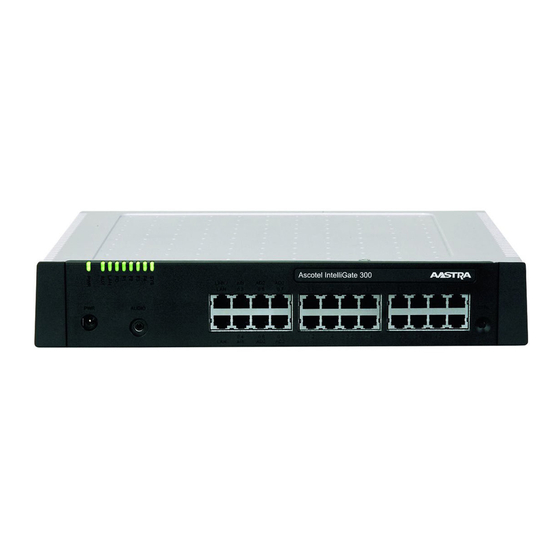
Ascotel® IntelliGate® 150/300 as of I7.9 System Overview This chapter provides a brief overview of the Ascotel® IntelliGate® with its system termi- nals and application possibilities. In addition, installation versions and positioning in relation to other Ascotel® products are shown. Finally, we talk about the topics of net- working possibilities, application interfaces, and connection possibilities. - Page 16 Ascotel® IntelliGate® 150/300 as of I7.9 Basic Systems Ascotel® IntelliGate® 150/300 is a family of communication systems. While the A150 and A300 are based on the same fundamental system, they differ in their expan- sion possibilities. All the connections and control elements are accessible from the front. The display elements are arranged so that they remain visible whatever the installation posi- tion.
- Page 17 – – – – – – – – – – – – – – – – – – – – – – hazards Combination of Softphones on the PC with an (AD2) system terminal. Requires an Aastra M535 expansion keypad System Overview...
- Page 18 Ascotel® IntelliGate® 150/300 as of I7.9 Installation versions Ascotel® IntelliGate® 150 and Ascotel® IntelliGate® 300 are suitable for both desk- top installation, wall mounting and installation in a 19" rack system. Covers for con- necting cables and special installation covers for rack installation are available sep- arately.
- Page 19 Ascotel® IntelliGate® 150/300 as of I7.9 Positioning Applications range from very small offices and branches (A150) to small and me- dium-sized companies (A300). The diagram below shows the positioning in relation to the number of users com- pared with other Ascotel® products. The information relates to non-networked stand-alone systems.
- Page 20 Ascotel® IntelliGate® 150/300 as of I7.9 Networking Possibilities The networking of several systems is possible both in a private network (PISN) and in an Ascotel® IntelliGate® Net (AIN). It is possible to combine systems of the family Ascotel® IntelliGate® 2025/2045/2065 and Ascotel® IntelliGate® 150/300. Ascotel®...
- Page 21 Ascotel® IntelliGate® 150/300 as of I7.9 Application interfaces The most important interface for own and third-party applications is the interface of the Open Interfaces Platform (OIP). This open interface allows the applications to be deeply integrated with telephony. The user is then able to benefit from a highly convergent complete system (telephony and IT system).
- Page 22 Ascotel® IntelliGate® 150/300 as of I7.9 Connection options Telefonia digitale Apparecchi comfort e selettori di linea digitali (DTMF / DEC) Sistema Ascotel DECT cordless integrato Posto operatore Office 45 Apparecchi comfort ISDN Ethernet Applicazioni esterne Fax-Server S extern Fax 1..3 (2B+D) Terminale IP Terminali propietari IP (Softphone)
-
Page 23: Expansion Stages And System Limits
Ascotel® IntelliGate® 150/300 as of I7.9 Expansion Stages and System Limits Within the system limits the basic systems can be expanded using interface cards, sys- tem modules and licences. To adapt the system ideally to suit the customer require- ments, the available expansion possibilities and system limits need to be known. With the project data the optimum hardware configuration is easily determined using the Project Manager. -
Page 24: Basic Systems
Ascotel® IntelliGate® 150/300 as of I7.9 Basic Interface Mounting System Wiring systems cards options modules adapter T/S Typ0 2 x T/S 8P LAN Switch Cable cover set WA-TS0 TIC-2TS SM-LAN8 Ascotel IntelliGate 150 Rack-mounting 3 x T/S + 1 x T 1 x DSP T/S Typ1 set for A150... -
Page 25: Interfaces
Ascotel® IntelliGate® 150/300 as of I7.9 3. 2. 1 Interfaces The following mainboard interfaces can be accessed only when the housing cover of the basic system is open: Tab. 2 Mainboard Interfaces A150 A300 Designation / Remarks Slots for interface cards IC1...IC4 / with snap mechanism Slots for system modules, type 1 SM1 / three system modules, stackable... - Page 26 Ascotel® IntelliGate® 150/300 as of I7.9 Mainboard EIM card holder Connector for fan (A300) (A300) (A300) (A300) Interfaces internal Ethernet (A300) (A300) LED display LINK / (A300) AUDIO CTRL Supply Audio Prog. button Front input input panel Legend: IC1...IC4 Slots for interface cards (trunk cards, terminal cards and options cards) WA0...WA4Slots for Wiring Adapter and LAN switch modules Slot for stackable system modules, type 1 (DSP modules) Slot for stackable system modules, type 2 (for future expansions)
-
Page 27: Basic Functions
Ascotel® IntelliGate® 150/300 as of I7.9 3. 2. 2 Basic functions The basic functions of the systems depend first and foremost on the available DSP resources (DSP = Digital Signal Processor). The DSP chip on the mainboard pro- vides signal processing functions for conference circuits, DTMF sender and receiver, compression of voice data, etc. - Page 28 Ascotel® IntelliGate® 150/300 as of I7.9 Selectable additional functions of the basic systems The basic systems provide expanded additional functions as indicated in the fol- lowing table. All the possible combinations are listed, with the maximum number of voice channels. For this the DSP chip on the mainboard has to be loaded with different firmware.
-
Page 29: Expansion With Cards And Modules
Ascotel® IntelliGate® 150/300 as of I7.9 3. 3 Expansion with cards and modules A basic system can be individually expanded using interface cards and system modules. The number of available expansion slots depends on the basic system (see "Interfaces", page 25). -
Page 30: Trunk Cards
Ascotel® IntelliGate® 150/300 as of I7.9 3. 3. 1. 1 Trunk cards The trunk cards contain interfaces for connection to the analogue public network (POTS), the digital public network (ISDN) or for networking systems to create a pri- vate telephony network (PISN). The trunk cards can be used and operated on any slots for interface cards. -
Page 31: Terminal Cards
Ascotel® IntelliGate® 150/300 as of I7.9 3. 3. 1. 2 Terminal cards Terminal cards are used for connecting digital and analogue voice and data termi- nals such as: On terminal cards with S and T interfaces the ratio of S to T interfaces is determined by the type and plug-in orientation of the wiring adapters (see "Wiring Adapter", page... -
Page 32: Option Card
Ascotel® IntelliGate® 150/300 as of I7.9 3. 3. 1. 3 Option card The ODAB options card contains relays, control inputs and an analogue terminal circuit for connecting a door intercom (TFE). The I/Os of the options card are partly configurable and can be used for the following purposes: •... -
Page 33: System Modules
Ascotel® IntelliGate® 150/300 as of I7.9 3. 3. 2 System modules System modules expand the resources of the basic systems, allowing the system to be expanded step by step in line with requirements. 3. 3. 2. 1 DSP module Some system functions require additional signal processing capacity. This is achieved using DSP modules (DSP stands for Digital Signal Processor). - Page 34 Ascotel® IntelliGate® 150/300 as of I7.9 tions. Some of these functions are subject to a licence (see also "Licence-related system limits", page 47). • DECT Operation of a DECT system with cordless terminals. In the case of connections between DECT and non-DECT environments the voice data has to be converted. This process requires DSP capacity.
- Page 35 Ascotel® IntelliGate® 150/300 as of I7.9 Expanded (G.729 only) mode there are more voice channels available per node than in hybrid mode. However the quality of the audio data is somewhat poorer as a result of the compression. The configured mode is always valid for the entire node.
- Page 36 Ascotel® IntelliGate® 150/300 as of I7.9 - Two VoIP channels per system can be used without a licence. - The VoIP channels of the mainboard can be combined with VoIP channels of DSP cards. – If Voice Mail channels are configured, the two basic Voice Mail chan- nels that can be used without a licence are redundant (see Tab.
-
Page 37: Lan Switch Module
Ascotel® IntelliGate® 150/300 as of I7.9 3. 3. 2. 2 LAN switch module The LAN switch module SM-LAN8 can be used to set up a compact data network capable of connecting up to 8 users. The module has the following features: •... - Page 38 Ascotel® IntelliGate® 150/300 as of I7.9 Example: The schematic diagram shows an A300 fitted with two LAN switch modules and three AD2 terminal cards (the greyed LAN switch modules represent alternative component configurations). This means that the front panel provides 16 RJ45 sock- ets connected with Ethernet and AD2 interfaces.
-
Page 39: Wiring Adapter
Ascotel® IntelliGate® 150/300 as of I7.9 3. 3. 3 Wiring Adapter The wiring adapters route the interfaces of the various interface cards with the right connection diagram to the RJ45 sockets on the front panel. The adapters are fitted to WA1...WA4 sockets. WA-TS0 WA-TS1 WA-2W... -
Page 40: Expansion To An Isylink System
Ascotel® IntelliGate® 150/300 as of I7.9 3. 4 Expansion to an isyLink system 3. 4. 1 What’s isyLink? Ascotel® IntelliGate® isyLink (IntelliGate System Link) allows you to easily couple two Ascotel® IntelliGate® systems via a RJ45 patch cable and, thus, increase the number of connection ports for digital and analogue terminals. -
Page 41: Application Possibilities
Ascotel® IntelliGate® 150/300 as of I7.9 3. 4. 2 Application possibilities Ascotel® IntelliGate® isyLink can be used with the systems Ascotel® IntelliGate® 150 (A150) and Ascotel® IntelliGate® 300 (A300). The following combinations are possi- ble: Tab. 13 Possible isyLink combinations isyMaster isySatellite Combination 1:... -
Page 42: Isylink Set H
Ascotel® IntelliGate® 150/300 as of I7.9 3. 4. 3. 2 isyLink set H This set is suitable for hybrid systems which besides G.711 also require the coding method according to the G.729 standard, e. g. for remote IP terminals or for con- nection to an SIP provider. -
Page 43: System Limits
Ascotel® IntelliGate® 150/300 as of I7.9 3. 5 System Limits System limits are defined on the one hand by the existing hardware with its expan- sion possibilities and on the other by the limits set in the software. The software limits can be enabled in part by licences. - Page 44 Abbreviated dialling numbers + PISN users 1500 1500 1500 1500 Line keys per key telephone Busy lamp fields for SIP/Aastra SIP terminals Switch Groups Positions per switch group Hotline destinations Emergency number destinations Emergency numbers Allocations of external call numbers to internal call num-...
-
Page 45: Terminals
Expansion keypads on IP system terminals expansion keypads Aastra M670i, Aastra M675i Alpha keyboard (AKB) only 1 Operator each, DECT/DCT terminal, Aastra 2380ip, Office 1600IP Limited by the maximum number of terminals With DECT on only one system Licences required 3. - Page 46 Aastra 2380ip, Aastra 5360ip, Aastra 5370ip, Aastra 5380ip, Office 1600IP, SIP terminals IP Operator Consoles Office 1560IP, Aastra 5380ip Aastra SIP terminals Aastra 6730i, Aastra 6731i, Aastra 6751i, Aastra 6753i, Aastra 6755i, Aastra 6757i Aastra 6739i Virtual and GSM termi-...
-
Page 47: Terminal And Network Interfaces
Ascotel® IntelliGate® 150/300 as of I7.9 3. 5. 3 Terminal and network interfaces Tab. 16 Terminal and network interfaces Ascotel® Ascotel® isyLink AIN with Max. number... Intelli- Intelli- A300 + A300 as Gate® 150 Gate® 300 A300 Master Total terminal interfaces (AD2, a/b, S) 22+22 AD2 terminal interfaces 20+20... - Page 48 Ascotel® IntelliGate® 150/300 as of I7.9 – ATASpro Gateway – Office 1560/Office 1560IP – Office 1600/Office 1600IP – Trial Licence, Office 1560x, Office 1600x, CTI A detailed description of the OIP licences can be found in the System Manual "Open Interfaces Platform". The following licences are managed in the PBX: •...
- Page 49 One licence is required per terminal to operate non-Aastra SIP terminals on As- cotel® IntelliGate®. The licences are needed when registering the terminals on the system and can be used even if "Aastra SIP Terminals" licences are missing. • Aastra SIP Terminals...
- Page 50 Note: For the "Aastra Mobile Client" licence the printout of the licence docu- ment contains not only the licence code but also an Aastra Mobile Cli- ent access code. You will need the access code to start the Aastra Mobile Client administration on the licence server. The administration...
- Page 51 Ascotel® IntelliGate® 150/300 as of I7.9 • Analogue Modem This licence allows remote maintenance of an A150/300 using an analogue mo- dem. For this the Modem function must be allocated to the mainboard DSP. Transmitting event messages via an analogue modem is also possible. Ascotel®...
-
Page 52: Auto Attendant
Ascotel® IntelliGate® 150/300 as of I7.9 Ascotel® IntelliGate® Net In an AIN the licence must always be acquired on the nodes on which added voice memory capacity is required. Requirement: The DSP resources on each node must be available and allocated accordingly. •... - Page 53 Aastra Mobile Client Aastra 5300 Series IP Termi- Number of registered Aastra 5360ip, per licence 1 additional nals (Office IP Terminals) Aastra 5370ip and Aastra 5380ip IP sys- IP system terminal tem terminals Aastra 2380ip Number of registered Aastra 2380ip IP...
- Page 54 SIP Access Channels, unlimited – VoIP Channels for Standard Media Switch, unlimited – Terminals, unlimited – Aastra 5300 Series IP Terminals (Office IP Terminals), unlimited – Aastra 2380ip, unlimited – Analogue Modem The licences are not visible in AIMS. Trial licences Trial licences are available for some functions.
-
Page 55: Power Supply-Related Limits
Terminals, unlimited • Aastra SIP Terminals, unlimited • VoIP Channels for Standard Media Switch, unlimited • Terminals, unlimited • Aastra 5300 Series IP Terminals (Office IP Terminals), unlimited • Aastra 2380ip, unlimited • Analogue Modem Enterprise Voice Mail • •... - Page 56 LEDs on terminals and expansion keypads: 20% illuminated he value applies to hardware version 2. The value for hardware version 1 is 60 mW lower. An Aastra M535 always requires a power supply unit for each AD2 interface Overload shutdown If the rated power is exceeded the power supply is disconnected.
-
Page 57: Limits Per Terminal Interface
Ascotel® IntelliGate® 150/300 as of I7.9 If an overload occurs, reduce the required supply power (e.g. by powering DECT ra- dio units or system terminals locally). 3. 5. 5. 2 Limits per terminal interface The power supply-related limit per terminal interface depends on the following variables: •... -
Page 58: Installation
Ascotel® IntelliGate® 150/300 as of I7.9 Installation This Chapter tells you the ways in which Ascotel® IntelliGate® 150/300 can be installed and the conditions to be observed. It also includes the mounting into a 19” rack, the correct way to connect the earthing, and the power supply. Other topics described in this Chapter comprise fitting the basic system with system modules, interface cards and the relevant Wiring Adapters. -
Page 59: Mounting The System
Ascotel® IntelliGate® 150/300 as of I7.9 4. 2 Mounting the System Ascotel® IntelliGate® 150/300 is suitable for both wall and desktop installation as well as for mounting in a 19” rack. Different mounting sets are available in each case. 4. 2. 1 Equipment supplied The equipment supplied with the Ascotel®... -
Page 60: Rack-Mounting Set For A150
Ascotel® IntelliGate® 150/300 as of I7.9 4. 2. 2. 2 Rack-mounting set for A150 Equipment supplied: • 2 mounting plates for rack installation • Screw set 4. 2. 2. 3 Rack-mounting set for A300 Equipment supplied: • 2 mounting plates for rack installation •... -
Page 61: Safety Regulations
Ascotel® IntelliGate® 150/300 as of I7.9 4. 2. 4 Safety regulations Be sure to observe the following safety regulations before carrying out work inside a basic system: Warning Components, interface cards or system modules can be damaged by electrical voltage. Always disconnect the system from the power supply before removing the housing cover. - Page 62 Ascotel® IntelliGate® 150/300 as of I7.9 ≥ 100 ≥ 100 ≥ 30 ≥ 95 ≥ 5 All dimensions in mm Fig. 16 Minimum distances for wall mounting (front panel facing to the right) ≥ 100 ≥ 95 ≥ 5 ≥ 100 ≥...
-
Page 63: Drilling Plan
Ascotel® IntelliGate® 150/300 as of I7.9 4. 2. 5. 2 Drilling plan The system is suspended into two premounted wall screws using the suspension points in the housing base. Depending on the type of mounting, these are the sus- pension points marked under position A or B on the drilling plan. The system is se- cured with a third screw to prevent it from being dislodged accidentally (position C). -
Page 64: Drilling Template
Ascotel® IntelliGate® 150/300 as of I7.9 4. 2. 5. 3 Drilling template The packaging box of the basic system can also be used for marking out the drill holes. To do so it is best to detach the part of the inner packaging box that contains the drill holes. -
Page 65: Wall-Mounting Procedure
Ascotel® IntelliGate® 150/300 as of I7.9 4. 2. 5. 4 Wall-mounting procedure Materials required: • Screw set for wall/desktop installation • 6 mm drill • Screwdriver To mount the system to the wall proceed as follows: Using the drill template or the instructions on the drill plan to mark out the three drill holes. -
Page 66: Desktop Installation
Ascotel® IntelliGate® 150/300 as of I7.9 4. 2. 6 Desktop installation To protect the cable connections the system can also be secured using three screws. The same drilling plan (see Fig. 18) and the same procedure apply as for wall mounting (see "Wall-mounting procedure", page 65). -
Page 67: Rack-Mounted Installation
Ascotel® IntelliGate® 150/300 as of I7.9 4. 2. 7 Rack-mounted installation The rack-mounting set A150 or A300 allows the system to be installed horizontally into a 19” rack. Be sure to observe the following: • The system takes up the space of 1.5 height units (units) inside the 19” rack. (1 unit corresponds to 44.45 mm). -
Page 68: Rack-Mounting Procedure
Ascotel® IntelliGate® 150/300 as of I7.9 4. 2. 7. 1 Rack-mounting procedure Materials required: • Rack-mounting set for A150 and A300 • Screw set for wall/desktop installation • Screwdriver For the rack-mounting of the A150/300 proceed as follows: Pull off the screw covers on the left and right of the front panel. Secure the mounting plates to the basic system using the M4 screws. -
Page 69: Installing The Fan
Ascotel® IntelliGate® 150/300 as of I7.9 4. 2. 7. 2 Installing the fan Materials required: • Fan from rack-mounting set A300 • 2 screws from the rack-mounting screw set A300 • Screwdriver To install the fan proceed as follows: Disconnect the system from the power supply. Warning Be sure to observe the "Safety regulations", page... -
Page 70: Installing The Cable Cover
Ascotel® IntelliGate® 150/300 as of I7.9 4. 2. 7. 3 Installing the cable cover Materials required: • Cable cover set for A150/300 • Screwdriver To install the cable cover proceed as follows: Pull off the screw covers on the left and right of the front panel. Use the M4 screws of the cable cover set to secure the brackets for the cable cover to the basic system. -
Page 71: Earthing And Protecting The System
Ascotel® IntelliGate® 150/300 as of I7.9 4. 3 Earthing and protecting the system The protective earth and equipotential bonding are important integral parts of the safety concept: Standard EN 60950 relevant to safety matters stipulates protective earthing. Warning High leakage current. Establish an earth connection before connecting to the telecommunica- tions network. -
Page 72: Connecting The Earthing
Ascotel® IntelliGate® 150/300 as of I7.9 4. 3. 1 Connecting the earthing The system’s earthing connection is located at the front left on the underside and can only be connected once the housing cover has been removed. The earthing wire is secured by a screw, spring washer and serrated lock washer, which are in- cluded in the screw set A150/300. - Page 73 Ascotel® IntelliGate® 150/300 as of I7.9 Fig. 24 Earthing of the system in the case of an indirect connection and direct connection Note In the case of an indirection connection make sure that the system’s earthing wire does not form any earth loops with the earthed cable screenings of the installation cables leading up to the (main) distribution frame.
-
Page 74: Connecting The Cable Screening
Ascotel® IntelliGate® 150/300 as of I7.9 4. 3. 2 Connecting the cable screening When using shielded installation cables also use shielded RJ-45 connectors. In this way the shielding of the installation cables is automatically connected with the housing of the basic system and therefore with the building earth. Note Connect the cable screens to one another at the splitting point only. -
Page 75: Power Supply To The System
Ascotel® IntelliGate® 150/300 as of I7.9 4. 4 Power Supply to the System The system is powered as standard with 230 VAC or 115 VAC. To ensure that its op- eration is maintained even in the event of a mains outage, an external uninterrupt- ible power supply (UPS) must be used. -
Page 76: Uninterruptible Power Supply (Ups)
Ascotel® IntelliGate® 150/300 as of I7.9 4. 4. 2 Uninterruptible power supply (UPS) The use of an external uninterruptible power supply (UPS) guarantees operation even in the event of a mains outage. The UPS battery capacity is rated according to the system’s power requirements and the required bridging time. -
Page 77: Equipping The Basic System
Ascotel® IntelliGate® 150/300 as of I7.9 4. 5 Equipping the Basic System For an individual expansion the A150/300 basic system is equipped with interface cards, the appropriate wiring adapters and system modules. An overview can be found in the Chapter "Expansion Stages and System Limits", page 4. -
Page 78: Wiring Adapter
Ascotel® IntelliGate® 150/300 as of I7.9 Notes – The ODAB options card must be fitted to slot IC2 (A150) or slot IC4 (A300) if it is to be used for connecting a door intercom (see "Equip- ment on the ODAB options card", page 113). - Page 79 Ascotel® IntelliGate® 150/300 as of I7.9 Plug-in Port number Wiring Adapter Interface card orienta- tion WA-2W ETAB4 – EADP4 – EAD4C – EAD4V – EAAB2 – – – TIC-4AB – TIC-2AB – – – WA-1PRI TIC-1PRI – Test – – SM-LAN8 –...
-
Page 80: Dsp Module
Ascotel® IntelliGate® 150/300 as of I7.9 Fig. 28 Jumper position on card ESST-2 Note Any incorrectly fitted or missing wiring adapters are signalled by a red flashing LED on the display after start-up (see "Wiring Adapter Malfunc- tion Mode", page 187). -
Page 81: Lan Switch Module
Ascotel® IntelliGate® 150/300 as of I7.9 4. 5. 4 LAN switch module LAN switch modules belong to the category of system modules and are fitted to the two neighbouring slots WA0…WA4 (see Fig. 8). The WA1...WA4 slots are also used for the Wiring Adapters. If a LAN switch module occupies slots WA1...WA4, no interface cards can be fitted to the corresponding slots IC1...IC4. -
Page 82: Component Mounting Rules
Ascotel® IntelliGate® 150/300 as of I7.9 4. 5. 5 Component mounting rules The component mounting rules mentioned in the previous chapters are listed here in an overview: • In principle the interface cards can be used in all the card slots. Exceptions: –... -
Page 83: Connecting The System
Ascotel® IntelliGate® 150/300 as of I7.9 4. 6 Connecting the System There are two possibilities for connection to the telephone network and the termi- nal-side cabling: • Direct connection • Indirect connection via (main) distribution frame and any universal building ca- ble installation (UBC) (see also Fig. -
Page 84: Connection Via Main Distribution Board
Ascotel® IntelliGate® 150/300 as of I7.9 4. 6. 2. 1 Connection via main distribution board Ascotel IntelliGate Fig. 30 Connection via main distribution board The interface sockets on the front panel are connected with the (main) distribution frame or the patch panels using either standard commercial or prefabricated con- necting cables. - Page 85 Ascotel® IntelliGate® 150/300 as of I7.9 Tab. 23 Diagram for a prefabricated connecting cable RJ45 Signal Stranded Cable desig- Core colour element nation Connection four-wire Two-wire connection white blue turquoise – violet – white orange turquoise – violet – white –...
-
Page 86: Connection To A Universal Building Cable Installation (Ubc)
Ascotel® IntelliGate® 150/300 as of I7.9 4. 6. 2. 2 Connection to a universal building cable installation (UBC) Fig. 32 Connecting to a UBC via a (main) distribution board (example) Subscriber Patch panel Telephone Subscriber-side Telephone Exchange side Exchange Fig. 33 Connecting to a UBC via wiring centre (example) Installation... -
Page 87: Cabling Interfaces
Ascotel® IntelliGate® 150/300 as of I7.9 4. 7 Cabling interfaces All the interfaces are routed to the front panel and are therefore accessible without opening the system. LINK / AUDIO CTRL Fig. 34 Interfaces on the front panel with port designation 4. -
Page 88: Network Interfaces
Ascotel® IntelliGate® 150/300 as of I7.9 4. 7. 2 Network Interfaces Equipping the system with interface cards provides the necessary network inter- faces. With the exception of the Ethernet interface, which also represents a network interface via SIP access, there are no network interfaces on the A150/300 main- board. - Page 89 Ascotel® IntelliGate® 150/300 as of I7.9 Basic access T, network-side Do not connect power supply NT1 Do not fit the jumper Fig. 36 Basic access on NT1 The assignment of the RJ45 connector is identical on the NT-side and on the side of the A150/300.
- Page 90 Ascotel® IntelliGate® 150/300 as of I7.9 Tab. 27 Cabling for basic access S external, networked with copper line PINX 1 signal PINX 2 signal Cable cores Basic access S external Basic access T Bus configuration S external is subject to the conditions that apply to terminal interface S (see "S terminal interfaces", page 106).
- Page 91 Ascotel® IntelliGate® 150/300 as of I7.9 X.25 connection in the D channel To transmit X.25 data from a PC via an A150/300 to the public ISDN network using the D-channel, you need the appropriate terminal adapters with S-interface, which are connected to the S-interfaces of interface cards. With the appropriate Wiring Adapters all the S/T interface cards can be used: Tab.
-
Page 92: Primary Rate Access T2
Ascotel® IntelliGate® 150/300 as of I7.9 4. 7. 2. 2 Primary Rate Access T2 With the appropriate interface cards and Wiring Adapters, T2 network interfaces can be made available at RJ45 sockets 1.1...40.1. For test purposes the T2 interface is also routed in parallel to port X.2. Note In normal operation the x.2 test socket must not be connected;... - Page 93 Ascotel® IntelliGate® 150/300 as of I7.9 Primary rate access T2, network side 230 VAC Exchange haz0051aadeb0 Fig. 41 Primary rate access T2 on NT1 Tab. 31 Cabling for primary rate access T2 Cable cores RJ45 A150/300 RJ45 Straight patch cables T2 sig- Socket T2 signal...
- Page 94 Ascotel® IntelliGate® 150/300 as of I7.9 Tab. 32 Cabling for primary rate access T2, networked with copper line RJ45 T2 signal Cable cores T2 signal RJ45 PINX 1 Crossed patch cables PINX 2 — — haz1129aaxxa0 — — — — —...
- Page 95 Ascotel® IntelliGate® 150/300 as of I7.9 Tab. 33 Cabling for primary rate access T2, networked with transmission equipment Cable cores Cable cores Signal Signal Straight patch Straight patch RJ45 T2 signal T2 signal RJ45 cables cables PINX 1 PINX 2 —...
- Page 96 Ascotel® IntelliGate® 150/300 as of I7.9 Tab. 34 Cabling for primary rate access T2, networked with leased-line or dial-up connection Cable cores T2 sig- T2 sig- Cable cores Straight patch Network Straight patch RJ45 T2 signal T2 signal RJ45 cables cables PINX 1 PINX 2...
-
Page 97: Network Interfaces A/B
Ascotel® IntelliGate® 150/300 as of I7.9 4. 7. 2. 3 Network interfaces a/b With the appropriate interface cards and Wiring Adapters, a/b network interfaces can be made available at RJ45 sockets 1.1...4.4. LINK / Fig. 45 Connection possibilities for a/b network interfaces In a direct connection the RJ45 connector is connected directly to the trunk cable using a crimp clip. - Page 98 Ascotel® IntelliGate® 150/300 as of I7.9 Cable Requirements Tab. 36 Requirements for a/b network connection cables Core pairs x cores 1 x 2 Stranded not required Wire diameter, core 0.4 … 0.8 mm Screening not required max. 2 x 250 Ω Resistance a/b Installation...
-
Page 99: Terminal Interfaces
Ascotel® IntelliGate® 150/300 as of I7.9 4. 7. 3 Terminal interfaces The number of available terminal interfaces on the mainboard can be increased by fitting interface cards. The RJ45 connector assignment is the same for interfaces of the mainboard and terminal cards. - Page 100 Ascotel® IntelliGate® 150/300 as of I7.9 AD2 bus configuration Depending on the line length 1 or 2 terminals can be connected on each AD2 inter- face. In this connection the Pocket Adapter (PA) and the DECT radio unit are also considered as terminals.
- Page 101 Aastra 5370 AD2 interface 1220 Aastra 5380 AD2 interface 1340 Aastra 5370, Aastra 5380 with power supply unit AD2 interface Aastra M530 expansion keypad Aastra 5370 Aastra M530 expansion keypad Aastra 5380 Aastra M535 expansion keypad Aastra 5370, Aastra 5380...
- Page 102 Notes – If another terminal is operated on the AD2 bus in addition to an Aastra 5370 or Aastra 5380, at least one terminal must be powered by a local power supply unit. – An Aastra 5370 or Aastra 5380 with an Aastra M535 expansion keypad always requires a power supply unit.
- Page 103 – Depending on the power available based on the line length on the AD2 bus the ringing and hands-free volume decreases accordingly. – The backlighting of the Aastra 5380 display is brighter if the terminal is powered by a power supply unit.
- Page 104 Ascotel® IntelliGate® 150/300 as of I7.9 Rating examples Example 1: Office 45 with one expansion keypad (EKP) Maximal power requirements as per Tab. 39: 1320 mW Fig. 48 indicates: • Maximum line length for a wire diameter of 0.4 mm: 770 m •...
- Page 105 Ascotel® IntelliGate® 150/300 as of I7.9 Cable Requirements Tab. 40 Requirements for an AD2 bus cable Core pairs x cores 1 x 2 or 1 x 4 Stranded Wire diameter, core 0.4…0.6 mm Screening recommended < 130 Ω (1 MHz) Characteristic impedance Note: max.
-
Page 106: S Terminal Interfaces
Ascotel® IntelliGate® 150/300 as of I7.9 4. 7. 3. 2 S terminal interfaces With the appropriate interface cards and Wiring Adapters, S terminal interfaces can be made available at RJ45 sockets 1.1...4.4. LINK / Fig. 49 Connection possibilities for S terminal interfaces Connection Tab. - Page 107 Ascotel® IntelliGate® 150/300 as of I7.9 Tab. 42 S-bus configurations depending on line length and the number of terminals S bus Short Short, V-shaped Long Point-to-point Length (max.) System ↔ terminal 150 m 2 x 150 m 500 m 1’000 m Terminal 1 ↔...
- Page 108 Ascotel® IntelliGate® 150/300 as of I7.9 Ω Fig. 53 S bus, point-to-point Greater distances (up to 8 km) can be achieved using the S bus extension PT 10. Restrictions The maximum number of terminals per S bus is further restricted by the power re- quirements of the terminals and their supplementary equipment: Tab.
- Page 109 Ascotel® IntelliGate® 150/300 as of I7.9 RJ45, double Front view of RJ45 Connect housing screens Ω 2x100 haz0027aaena0 Fit resistors at bus extremity only Fig. 55 RJ45 connection, double socket Installation rules Always terminate the bus extremity with 2 x 100 Ω (0.25 W, 5%)! Cable Requirements Tab.
- Page 110 Ascotel® IntelliGate® 150/300 as of I7.9 Up to 8 terminals of different types can be connected to one S bus. • Standard ISDN terminals • ISDN Terminal Adapter • PC with ISDN card • Group 4 fax machines , etc. Two call connections are possible simultaneously for each S bus.
-
Page 111: A/B Terminal Interfaces
Ascotel® IntelliGate® 150/300 as of I7.9 4. 7. 3. 3 a/b terminal interfaces The a/b terminal interfaces of the mainboard are permanently routed to the RJ45 connector strip and labelled accordingly. With the appropriate interface cards and Wiring Adapters, additional a/b terminal interfaces can be made available at the RJ45 sockets 1.1...4.4. - Page 112 Ascotel® IntelliGate® 150/300 as of I7.9 Terminals The following analogue terminals can be connected to the system: • Analogue phones with DTMF or pulse dialling (earth key is not supported) • Radio units for cordless phones • Two-wire door intercoms with DTMF control functions •...
-
Page 113: Special Interfaces
Ascotel® IntelliGate® 150/300 as of I7.9 4. 7. 4 Special Interfaces 4. 7. 4. 1 Equipment on the ODAB options card The ODAB options card contains the following equipment: • 1 analogue terminal interface for connecting a door intercom • Relay outputs and control inputs for connecting a door intercom and/or other purposes. - Page 114 Ascotel® IntelliGate® 150/300 as of I7.9 Jumper Configuration The jumper configuration is shown in the following diagram. Three of the four IO ports are used for connecting the door intercom. A control input or a relay output is available for other purposes. Fig.
- Page 115 Ascotel® IntelliGate® 150/300 as of I7.9 RJ45 A150/300 RJ45 A150/300 – – – – – – – – – – – – Tab. 48 Connections for the options card ODAB IO port Connection Function Value 600 Ω – Ta, Tb Connection for two-wire door intercom sys- tem signal KT 1, 2...
- Page 116 Ascotel® IntelliGate® 150/300 as of I7.9 Points to be observed for the connection: • The door intercom system requires an external power supply. • The signal circuit does not require a power supply. • The speech path (a/b, no DC component) is connected to Ta and Tb. •...
- Page 117 Ascotel® IntelliGate® 150/300 as of I7.9 Relay and control inputs If the options card is fitted to slot IC1 (A150) or slot IC1, 2 or 3 (A300), the analogue terminal interface cannot be used. However two control inputs can be used for switching a switch group and two relay outputs for controlling external devices or equipment.
- Page 118 Ascotel® IntelliGate® 150/300 as of I7.9 RJ45 A150/300 RJ45 A150/300 Socket X2 Signal Socket X4 Signal – – – – I3-1 – I4-1 – I4-2 – I3-2 – – – – – Tab. 51 Connections of control inputs and relay outputs IO port Signal Function...
- Page 119 Ascotel® IntelliGate® 150/300 as of I7.9 Switch group interface The routing elements of switch groups 1..20 are controlled via control inputs I3 and I4. Control is effected using external switches (door contacts, time switches, etc.). The signal no-load voltage is approx. 40 VDC, the short-circuit current approx. 4 mA.
-
Page 120: Ethernet Interface
Ascotel® IntelliGate® 150/300 as of I7.9 4. 7. 4. 2 Ethernet Interface The A150/300 basic systems have a 2-port LAN switch 10/100 Base T. The Ethernet interfaces are permanently routed to the RJ45 connector strip and labelled accord- ingly. By fitting LAN switch modules to slots WA0...WA4 the number of Ethernet inter- faces can be increased by a maximum of 2 ×... - Page 121 Ascotel® IntelliGate® 150/300 as of I7.9 Combining Ethernet and AD2 interfaces LAN switch modules can be combined with AD2 terminal cards. In this case the LAN switch module assumes the function of two wiring adapters and routes the AD2 interfaces together with the Ethernet interfaces to the same RJ45 sockets on the front panel.
- Page 122 Ascotel® IntelliGate® 150/300 as of I7.9 Two possibilities for separating the signals are listed below: • Separating the signals in a double RJ45 socket • Splitting the signals after a single RJ45 socket using a Y-adapter with a wiring cir- cuit as shown in Fig.
- Page 123 Ascotel® IntelliGate® 150/300 as of I7.9 name on the DNS server. If logon is successful the system is accessible via the host name. If the logon to the DHCP server fails, the system deactivates DHCP temporar- ily and can be accessed via the static initialization value address. The system is then accessible with a direct connection via the IP address.
-
Page 124: Audio Interface
Ascotel® IntelliGate® 150/300 as of I7.9 4. 7. 4. 3 Audio interface The Audio interface can be used to • play music or an announcement on to connections with a caller on hold ("Music on Hold" function). • play music or an announcement for the Courtesy Service (announcement prior to answering), Voice Mail greetings or for "Music on Hold"... -
Page 125: General Bell
Ascotel® IntelliGate® 150/300 as of I7.9 4. 7. 4. 4 General bell One analogue terminal interface per system can be configured in such a way that it is used for connecting a general bell. The connection procedure is described in "a/b terminal interfaces", page 111. -
Page 126: Interface On The Pocket Adapter (Pa)
Ascotel® IntelliGate® 150/300 as of I7.9 4. 7. 4. 5 V.24 interface on the Pocket Adapter (PA) The PA provides a V.24 interface for connecting an AD2 interface with a PC. The PA's V.24 cable is connected to a serial interface on the PC Two terminals can be connected to an AD2 interface. - Page 127 Ascotel® IntelliGate® 150/300 as of I7.9 Settings The same communication parameters must be set on all the connected equip- ment. On the PA this is done using DIP switches S1... S8 (see Fig. 66). Transmission rate Flow control Connection "ON" TSD2 Connection haz1144aaena0 Fig.
- Page 128 Ascotel® IntelliGate® 150/300 as of I7.9 Transmission rate Tab. 60 Setting the transmission rate Switch S8 Switch S7 Switch S6 Transmission rate Test mode 19200 9600 4800 2400 1200 reserved Flow control Tab. 61 Setting the flow control Switch S5 Switch S4 Flow control none...
- Page 129 Ascotel® IntelliGate® 150/300 as of I7.9 Significance of the LEDs The 4 LEDs indicate the equipment status and the current direction of the data transmission. Tab. 63 LED display LED flashes LED on LED blinking LED flashes once twice RX A DTR B = on Data from PBX to V.24 (A) Xoff to V.24 (A)
- Page 130 Ascotel® IntelliGate® 150/300 as of I7.9 Tab. 64 Type of connectors on the interfaces to the Ascotel® IntelliGate® Device Type Connection type (connector on the equipment) Mainboard (20x5 only) D-sub, 9-pin (male) Pocket Adapter (PA) D-sub, 9-pin (female) Serial printer D-sub, 25-pin (female) D-sub, 9-pin or D-sub, 25-pin (male) Mini-DIN, 8-pin (female)
- Page 131 Ascotel® IntelliGate® 150/300 as of I7.9 Tab. 66 Straight cables (modem cables) Signal Cable cores Signal D-Sub-9 D-Sub-25 D-Sub-9 female female male SGND SGND haz0088aaxxa0 — Application — with Ascotel® Printer — IntelliGate® — Tab. 67 Straight cables (modem cables) for Mac applications Apple standard Mini-DIN, 8-pin Cable cores...
-
Page 132: Configuration
– Upload Manager (UM) and System Event Manager (SEM) (see "AIMS Managers", page 133) – Ascotel® Search and Smart Software Update (see "Auxiliary applications", page 134) See also: The Application Notes and Frequently Asked Questions (FAQs) in connec- tion with AIMS can be downloaded from https://pbxweb.aastra.com Configuration... -
Page 133: Aims Shell
Ascotel® IntelliGate® 150/300 as of I7.9 5. 1. 1 AIMS Shell The AIMS Shell is used to administer the systems, replicate the nodes of an Ascotel® IntelliGate® Net (AIN) and set the access parameters. The numbering plan of a pri- vate leased-line network can also be specified here across all the nodes. -
Page 134: Auxiliary Applications
Ascotel® IntelliGate® 150/300 as of I7.9 Symbol Manager Function Information Manager (IM) Information Manager (IM) supports the customers with helpful offline documentation. Upload Manager (UM) The Upload Manager (UM) is used to update the software of a sys- tem from the PC. System Event Manager (SEM) •... - Page 135 G.729 format. To be able to continue using existing, uncompressed voice messages and greetings in G.711 format, you need to compress the message and greetings first. The Aastra IntelliGate® WAV Converter → is provided for this very purpose in the AIMS shell under...
-
Page 136: Access Types
Ascotel® IntelliGate® 150/300 as of I7.9 5. 2 Access types There are the following possibilities to access the PBX with AIMS: Local access via v.24 interface on the Pocket Adapter Internal dial-up access via an S terminal interface Internal dial-up access via an a/b terminal interface Internal access via the LAN or directly External access via IP network External dial-up access via dial-in node (only in AIN) -
Page 137: User Access Control
Ascotel® IntelliGate® 150/300 as of I7.9 5. 3 User Access Control Access to the PBX configuration is password-protected. Any user wanting to log in to a PBX is prompted for his user name and password (access data). 5. 3. 1 User accounts and authorization profiles A user's authorizations are regulated by authorization profiles, which are assigned to the user accounts. -
Page 138: Administration Rights
Ascotel® IntelliGate® 150/300 as of I7.9 Tab. 70 Predefined authorizations of the authorization profiles 1st party Adminis- System- Features Attendant CTI user Support trator manager via LAN Administration rights • User Access Control – – – – – • Audio services –... -
Page 139: Interface Access
Ascotel® IntelliGate® 150/300 as of I7.9 Tab. 71 Authorizations for carrying out AIMS functions Features Installer System Manager Attendant • Upload (PC -> PBX) – – • Download (PPX -> PC) • Backup (PC -> Disk) • Restore (Disk -> PC) –... -
Page 140: User Accounts During Version Transfers
Ascotel® IntelliGate® 150/300 as of I7.9 • ATAS Allows third-party applications to communicate with the PBX via the IP network by means of the ATAS interface. This authorization is not intended for individual persons. • Remote maintenance using dial-up access Allows remote maintenance using dial-up access in principle. -
Page 141: Initialization Password
Ascotel® IntelliGate® 150/300 as of I7.9 user is authorized to configure offline without entering his password (auto login). If the PBX password is identical to the user's password, he can even access the PBX without password and configure online. 5. 3. 2. 1 Initialization password To access the default user account enter the following: Tab. -
Page 142: Change Password
Ascotel® IntelliGate® 150/300 as of I7.9 Note: When upgrading older systems whose passwords do not comply with these rules, you will be prompted to change the passwords the first time you access the configuration of the upgraded system. 5. 3. 2. 3 Change password Any user who is assigned the "User Access... -
Page 143: Password-Free Access
Ascotel® IntelliGate® 150/300 as of I7.9 profile in which the "Office 45" interface access is enabled. The profile also needs to be assigned the AIMS authorization level "Attendant" if the remote access status is to be changed. 5. 3. 4 Password-free access The control pilot key on the connector strip can activate a function that enables via AIMS password-free, local access with administration right... -
Page 144: Enabling Remote Access
Ascotel® IntelliGate® 150/300 as of I7.9 Entering the processes in the log Each access attempt generates an entry in the corresponding list. In the case of a remote maintenance access an entry will not be generated if re- mote maintenance is barred or if "CLIP required"... -
Page 145: Procedure For Remote Access
Ascotel® IntelliGate® 150/300 as of I7.9 Note: It is advisable not to keep the remote access authorization permanently activated. This ensures that the PBX cannot be manipulated from a remote location by unauthorized persons. 5. 4. 2 */# procedure for remote access Tab. -
Page 146: Function Keys For Remote Access Authorization
Ascotel® IntelliGate® 150/300 as of I7.9 5. 4. 3 Function keys for remote access authorization On system terminals (with the exception of Office 10) the */# procedure for ena- bling remote access authorization can be stored under a function key, providing the user has the appropriate authorization. -
Page 147: Exchanging Data Between Pbx And Pc
Ascotel® IntelliGate® 150/300 as of I7.9 5. 5 Exchanging data between PBX and PC The system and user data is stored in the PBX and on the PC's hard disk. Both data- bases are serviced by the AIMS Managers. To keep the databases at the same level, you need to exchange data between the databases. -
Page 148: Working Offline (Aims Database)
Ascotel® IntelliGate® 150/300 as of I7.9 5. 5. 1 Working offline (AIMS database) With the AIMS database you can only work in offline mode. The following functions are available: Open All the data from the selected PBX is loaded from the AIMS database into the PC’s main memory and made available for processing. -
Page 149: Working Online (Pbx Database)
Ascotel® IntelliGate® 150/300 as of I7.9 5. 5. 2 Working online (PBX database) Data in the PBX database can only be accessed in the online mode. The following functions are available: Connect The PBX is connected with the AIMS Shell and automatically loads the data of the PBX into the PC’s main memory. - Page 150 Ascotel® IntelliGate® 150/300 as of I7.9 Upload During an upload via the AIMS Shell the PBX data are written from the AIMS data- base into the PBX. During a data upload the PBX is automatically prebarred and then again released once the operation is completed.
-
Page 151: Import / Export Data
• Download, compress and upload existing voice messages and greetings The Aastra IntelliGate® WAV Converter is used for compressing and converts the wave files from audio format G.711 to audio format G.729. The compressed for- mat is needed if the Voice Mail System is operated in expanded mode. -
Page 152: Configuration Steps
Ascotel® IntelliGate® 150/300 as of I7.9 5. 6 Configuration Steps The configuration steps are based on the information determined during the plan- ning and, where applicable, the installation. 5. 6. 1 System initialization If a system is to be upgraded, it must first be in a defined state. This involves setting or deleting all the parameter values to their initialization value and carrying out a self-test. -
Page 153: Configuration With Aims (Online)
Ascotel® IntelliGate® 150/300 as of I7.9 See also: The procedural steps for configuring an individual system, a private net- work (PISN) or an Ascotel® IntelliGate® Net (AIN) are described in detail in AIMS help. 5. 6. 3 Configuration with AIMS (online) If a PBX that has already been configured is present, the configuration can be di- rectly loaded and edited with AIMS. -
Page 154: Reading Initialization Values
Ascotel® IntelliGate® 150/300 as of I7.9 The licences must be activated. The licence code can be edited both online and of- fline with AIMS: Type in the licence code under 1_2_2 "Licensing" in the system configuration. The licence code is stored in the EIM. Upload the system configuration data and restart the system;... -
Page 155: Operation And Maintenance
Ascotel® IntelliGate® 150/300 as of I7.9 Operation and Maintenance This chapter describes maintaining the system and configuration data as well as up- dating the system software. Replacing cards, modules and terminals are also described. The user interface of the basic system as well as operations supervision using the event message concept, the operating state display, and the error display are also topics cov- ered in this chapter. -
Page 156: System Software
Ascotel® IntelliGate® 150/300 as of I7.9 Mainboard Area of flash chips EIM card Area of RAM chips Fig. 70 Memories on the mainboard A150/300 6. 1. 1. 1 System software The entire system software package of the PBX is stored in serial Flash components in compressed form. -
Page 157: Boot Software
Ascotel® IntelliGate® 150/300 as of I7.9 wave files". This function is useful for a backup or if there is insufficient free storage space available in the serial Flash components for an update of the PBX software. → After the update the wave files are reloaded to the PBX with the function "Tools"... -
Page 158: System-Specific Data
Ascotel® IntelliGate® 150/300 as of I7.9 Configuration data is available for system terminals only. It is stored in a parallel Flash memory and saved during the AIMS backup. Configuration data can be modified either using AIMS or directly from the system terminal. -
Page 159: Update Software
Ascotel® IntelliGate® 150/300 as of I7.9 6. 2 Update Software 6. 2. 1 System software The PBX's system software is loaded using the AIMS Upload Manager or the addi- tional application "Smart Software Update". The PBX's system software also contains the software for the Office 45 system ter- minals, the DECT radio units and the Office 135 and Office 160 handsets. -
Page 160: Standard Upload
Ascotel® IntelliGate® 150/300 as of I7.9 "Options" pull-down menu → In menu itemOptions Settings the default settings for the communication link are configured. Please refer to the Help information to find out more about the in- dividual parameters. Monitor The Upload Monitor is an Upload Manager function and is called up using Options →... - Page 161 Ascotel® IntelliGate® 150/300 as of I7.9 Fig. 71 Software upload sequence During a standard upload the PBX remains operational during the upload phase. After a successful software upload, the PBX runs an automatic warm-start at the set time and restarts with the newly loaded system software. It is possible that there is insufficient storage space in Flash memory for the update of the PBX software.
- Page 162 Ascotel® IntelliGate® 150/300 as of I7.9 See also: For information on event messages and signal destinations, see "Event message concept", page 191. Initiating an upload process To ensure a successful software upload, carry out the following preparatory steps: → Backup). Recommendation: Use AIMS to save the configuration data (Tools If necessary: Save the wave files (Voice Mail, Courtesy and Music on hold)
-
Page 163: Emergency Upload Of The System Software
Ascotel® IntelliGate® 150/300 as of I7.9 If you need to stop the upload at any stage, click the "Cancel" button. The software upload is then stopped and the current system software remains in operation. Status display The status display provides information with date and time indications on the cur- rent software upload, including all the event messages output in connection with the current software upload. -
Page 164: Software Of Corded System Terminals
The software for the system terminals is contained in the PBX's system software and is therefore always updated along with the PBX's system software. The Office 10, Office 25 and Aastra 5360 system terminals do not have their own memory. The Office 35, Office 45, Aastra 5370 and Aastra 5380 system terminals and all IP system terminals (hardphones) have a flash memory. -
Page 165: Software For Dect Systems
Ascotel® IntelliGate® 150/300 as of I7.9 6. 2. 3 Software for DECT systems Ascotel® DECT radio unit haz1230aaena0 Flash memory Aerials Fig. 72 Ascotel® DECT radio unit The Flash memory on the Ascotel® DECT radio unit contains an area that cannot be modified. - Page 166 There is only one software for the handsets of the Aastra 600d series. It is included in the PBX software package and stored on the PBX file system. If the handset soft- ware is to be updated independently of the PBX software, it can be updated using FTP (File Transfer Protocol).
-
Page 167: Hardware Update
Ascotel® IntelliGate® 150/300 as of I7.9 6. 3 Hardware update Hardware maintenance comprises replacing cards and modules when there is a de- fect or for a generation change. Safety regulations must be observed and the step- by-step procedure must be followed. 6. -
Page 168: Disconnect System Power Supply
Ascotel® IntelliGate® 150/300 as of I7.9 Note: Prebarring the system can be dispensed with if all concerned are aware that existing connections will be disconnected. 6. 3. 1. 3 Disconnect system power supply Disconnect the system from the power supply. Warning Be sure to observe the "Safety regulations", page... -
Page 169: Eim Card
Ascotel® IntelliGate® 150/300 as of I7.9 6. 3. 2. 2 EIM card The EIM card must be replaced in the following cases: • A licence is transferred to another system of the same type • The mainboard is defective • The EIM card is defective A licence is transferred to another system of the same type A licence can only be transferred to a system of the same type. -
Page 170: Interface Cards
Ascotel® IntelliGate® 150/300 as of I7.9 Push the new EIM card under the guide tongues and through to the stop in the chip-card holder. Fit the housing cover. Reconnect the system to the power supply. Notes: – The EIM card must be fitted before the system is put into operation. The PBX will not start without the EIM card. -
Page 171: New Card With Fewer Ports
Ascotel® IntelliGate® 150/300 as of I7.9 Fit the housing cover. Reconnect the system to the power supply. 6. 3. 3. 2 New card with fewer ports A card is replaced by a similar card with fewer ports. Procedure: Change the card and put the PBX into operation again. Similar procedure as de- scribed in "Replacing a defective interface card", page 170. -
Page 172: Change Slot
Ascotel® IntelliGate® 150/300 as of I7.9 The system configuration data (User No., User configuration, etc.) of the terminals on the new ports is created as new data (initialization values). Tab. 79 Example: Expanding the number of terminal or network interfaces SC-08AD2 →... -
Page 173: System Modules
Ascotel® IntelliGate® 150/300 as of I7.9 6. 3. 4 System modules The system module category includes the DSP cards SM-DSP1 and SM-DSP2, which are equipped on slot SM1, and the LAN Switch Module SM-LAN8, which is equipped in two adjacent wiring adapter slots. 6. -
Page 174: Mainboard
Ascotel® IntelliGate® 150/300 as of I7.9 6. 3. 5 Mainboard If the components on the mainboard are defective or permanently faulty, the entire basic system with the metal chassis must be replaced. Replacing the Mainboard → Backup). If still possible, save the configuration data using AIMS (Tools Disconnect the system from the power supply. -
Page 175: Dect Terminals
Ascotel® IntelliGate® 150/300 as of I7.9 Relocating a terminal The terminal configuration data of a system terminal can be copied to another ter- minal with the same level of added features using the AIMS Configuration Manager → → Paste). You can choose the parameters to copy from a list. (Edit Copy Edit... -
Page 176: Generation Change
AIMS 7.6 in the readme.txt file. – An Aastra 5370ip logged on to the system as an Office 35IP prior to the upgrade to I7.5 (= Office 70IP-b) can still be used. If the terminal is logged on to the system as an Aastra 5370ip a software update is automatically initiated. -
Page 177: System Downgrade
(x<5). This is not possible with a terminal that was logged on as an Aastra 5370ip as it can no longer be logged on as an Office 35IP. If this is required nonetheless the Office 35IP software must be reloaded onto the terminal using the IP Update Manager. -
Page 178: User Interface
Ascotel® IntelliGate® 150/300 as of I7.9 6. 5 User interface The user interface on the front panel consists of the display elements and a pilot key. It is used to indicate operating states and carry out functions. 6. 5. 1 Display elements The front panel features an LED display with a total of 9 labelled LED. -
Page 179: Pilot Key (Ctrl Key)
Ascotel® IntelliGate® 150/300 as of I7.9 Example: In the following display pattern the LED lights up green for 500 ms and is then inac- tive for 500 ms. Then it lights up green again for 500 ms ... etc. Tab. 81 Example of a display pattern LED activation period Description... -
Page 180: Carrying Out Functions
Ascotel® IntelliGate® 150/300 as of I7.9 Different actions are carried out depending on how long the key is pressed and the system’s current operating state. The duration of the keypress is divided into three time intervals: Tab. 83 Keypress duration, pilot key Designation Abbreviation Keypress duration Short keypress (Short Click) -
Page 181: Operating Modes And Display Priorities
Ascotel® IntelliGate® 150/300 as of I7.9 6. 5. 4 Operating modes and display priorities The system software of the A150/300 recognizes various operating modes, which are displayed with the LEDs F0, F1, F2, F3, F4 and SYS. In the following these dis- plays are referred to as combination patterns or patterns and are numbered for easy reference. -
Page 182: Startup Mode
Ascotel® IntelliGate® 150/300 as of I7.9 6. 5. 4. 1 Startup Mode Startup begins as soon as power is supplied or after a restart/first start, and ends when the system enters Normal Mode. The LED combination patterns 1...9 indicate the individual startup phases in chronological order and also serve as a progress in- dicator. -
Page 183: Normal Mode
Ascotel® IntelliGate® 150/300 as of I7.9 6. 5. 4. 2 Normal Mode Normal Mode means that the system software is running fault-free. Depending on the situation the LEDs display the following combination patterns: Tab. 87 Combination patterns in Normal Mode Pattern Meaning System in normal operation... -
Page 184: Application Command Mode
Ascotel® IntelliGate® 150/300 as of I7.9 6. 5. 4. 4 Application Command Mode The Application Command Mode is used to enable or disable password-free access (pattern 15) and remote access to the AIN via an external dial-up connection (pattern 16). The Application Command Mode is indicated by the SYS-LED flashing green-or- ange. -
Page 185: Boot Command Mode
Ascotel® IntelliGate® 150/300 as of I7.9 Enabling / disabling the dial-up connection to the AIN The following sequence changes the status of the remote access to the AIN via an external dial-up connection: Requirement: The system has been started up and is running normally. Press the pilot key with a long keypress (LC). - Page 186 Ascotel® IntelliGate® 150/300 as of I7.9 Carrying out a first start The following sequence carries out a system first start. Note: A system first start deletes all the configuration data, which is reset to its initialization values. Save the data beforehand with a backup. The data stored on the EIM card is not deleted by a first start of the PBX, and remains available.
-
Page 187: Wiring Adapter Malfunction Mode
Ascotel® IntelliGate® 150/300 as of I7.9 Initialization values of the IP address data: • IP address: 192.168.104.13 • Subnet mask: 255.255.255.0 • Gateway: 0.0.0.0 6. 5. 4. 6 Wiring Adapter Malfunction Mode The system switches to this mode if an unsuitable wiring adapter is fitted into one of the wiring adapter slots. -
Page 188: Boot Mode
Ascotel® IntelliGate® 150/300 as of I7.9 6. 5. 4. 8 Boot Mode The boot mode enables an Emergency Upload via the Ethernet interface. This is re- quired whenever there is no longer any executable system software stored on the basic system for whatever reason or if a downgrade to an older software version is to be carried out. - Page 189 Ascotel® IntelliGate® 150/300 as of I7.9 Category / Descrip- Error Remedy tion E-505 Hardware: Replace basic system DRAM defective E-530 Hardware: Replace basic system BBT Integrity Check: No free replacement blocks available E-531 Hardware: Replace basic system BBT Integrity Check: Inconsistent Bad Block Table E-532...
- Page 190 Ascotel® IntelliGate® 150/300 as of I7.9 Category / Descrip- Error Remedy tion Factory Server Error: For the manufacturer No DHCP only Factory Server Error: For the manufacturer No TCP connection only E-534 Software: Contact Support. The corrupt file system file system must be reformatted.
-
Page 191: Operations Supervision
Ascotel® IntelliGate® 150/300 as of I7.9 6. 6 Operations supervision 6. 6. 1 Event message concept The PBX generates an event message every time an event or error occurs. The event tables in the Fault & Maintenance Manager are used to specify how often an event message of a particular type may be generated over a given time period be- fore the event message is sent to the allocated signal destinations. -
Page 192: Event Types
Ascotel® IntelliGate® 150/300 as of I7.9 6. 6. 1. 1 Event types Tab. 96 Event types, in alphabetical order Event/ error message Trigger condition Details ACD server out of service ACD server defined as destination but not Date, time responding. ATAS: connection established ATAS: connection (re) established Date, time... - Page 193 The maximum duration of two hours for the Date, time tions expired temporary licence activation has expired. Limits reached for busy lamp A busy lamp field on an SIP/Aastra SIP termi- Terminal ID, key number, date, field nal could not be configured because the sys- time tem limit for the platform has been reached.
- Page 194 Ascotel® IntelliGate® 150/300 as of I7.9 Event/ error message Trigger condition Details Node: A node is reconnected with the Master for a Node number, date, time Connection re-established certain amount of time (configurable) after an interruption. NTP: Synchronisation failed Time synchronization via the NTP server (NTP Date, time = Network Time Protocol) has failed.
- Page 195 GSM terminals. All the integrated GSM terminals remain blocked until there are enough GSM licences. Too few licences for IP system An Aastra 5360ip/5370ip/5380ip was unable Date, time terminals to register because there are too few IP system terminal licences.
-
Page 196: Event Tables
Ascotel® IntelliGate® 150/300 as of I7.9 Event/ error message Trigger condition Details User does not answer No answer to incoming DDI call from user on S DDI No., date, time bus or AD2 Wake-up call unanswered Room wake-up call not answered Room No., date, time Wrong or missing wiring There is no wiring adapter in the wiring... -
Page 197: Signal Destinations
Ascotel® IntelliGate® 150/300 as of I7.9 sage is sent to the signal destinations immediately; while the event type "No Re- sponse from Network", no event message needs to be sent to the signal destina- tions. 6. 6. 1. 3 Signal destinations 4 signal destinations can be configured in the Fault &... - Page 198 Ascotel® IntelliGate® 150/300 as of I7.9 Fig. 77 Overview of connection possibilities for the various signal destinations Signal Destination: terminal Depending on the allocated event table, event messages are sent to all the system terminals that have a display and are entered in message group 8. External signal destinations Depending on the event table allocated, event messages are sent to a specified ex- ternal signal destination.
- Page 199 Ascotel® IntelliGate® 150/300 as of I7.9 Signalling an event message to an external signal destination Event message Signalling delayed up to 5/240 min. Call external signal destination Wait 30 s Status Busy Connection established ext. signal dest,? Not available / blocked Dialling attempts Delay 40 s...
- Page 200 Ascotel® IntelliGate® 150/300 as of I7.9 The following principles govern the way event messages are signalled to an exter- nal signal destination: • Individual event messages are not signalled if they occur at short intervals. The event messages are stored temporarily for 5 minutes and then sent together to the external signal destination.
- Page 201 Ascotel® IntelliGate® 150/300 as of I7.9 V.24 (PBX) RTS/CTS port ISDN ISDN (PBX) card ISDN (PBX) gateway haz1192aaena0 Fig. 79 Overview of connection possibilities for external signal destinations Two external signal destinations ("Preferred event message destination" and "Alterna- tive event message destination") can be configured.
- Page 202 Ascotel® IntelliGate® 150/300 as of I7.9 Other necessary configurations The following parameters must also be configured. • In the Fault & Maintenance Manager: System ID of the PBX. This is important so that the PBX can be identified by the SEM.
- Page 203 Ascotel® IntelliGate® 150/300 as of I7.9 Note: Event tables and signal destinations should be set in such a way that the event message Internal event message destination missing" is signalled immediately to any signal destination still available. Configuring a local signal destination on a V.24 interface The local signal destination is connected to the V.24 interface of a Pocket Adapter (PA).
- Page 204 Ascotel® IntelliGate® 150/300 as of I7.9 PC format The event signal format "PC" is required if a PC is configured as the local signal des- tination using the System Event Manager (SEM). Configuring a local signal destination on an S interface / ISDN As with an external signal destination the event message opens a PPP communica- tion channel from the PBX to a Terminal Adapter, connected either directly to a PC with the System Event Manager (SEM) or indirectly via a LAN (ISDN gateway).
- Page 205 Ascotel® IntelliGate® 150/300 as of I7.9 • Call number of the local signal destination (the call number is not checked by the PBX, if the entered call number is incorrect, the PBX will issue the event mes- sage "Internal message destination is missing").
-
Page 206: Snmp Destination
Ascotel® IntelliGate® 150/300 as of I7.9 The Event Log consists of four protocols: • Event messages (max. 254 entries) • System failures (max. 80 entries) • Power failures (max. 10 entries) • Card failures (max. 150 entries) If the maximum number of entries is exceeded, the oldest entry in each case is de- leted. -
Page 207: System Event Manager Sem
(Managed Objects: MO). These objects and the related event messages are stored in an object library referred to as the Management Information Base (MIB). The current MIB version can be downloaded from https://pbxweb.aastra.com. The user name and password are required in order to access the data. Registration with the "Aastra Application Parter Programm"... -
Page 208: Operating State And Error Displays
Ascotel® IntelliGate® 150/300 as of I7.9 The relevant TCP port has to be activated for data transmission. The event types can be assigned different priorities in the SEM Configurator. The SEM Configurator is also used to set, for each individual AIMS database, the way in which the SEM Server should respond to each incoming event message (e.g. -
Page 209: Other Aids
Ascotel® IntelliGate® 150/300 as of I7.9 Error Displays Whenever the system detects an error, it displays the corresponding error code in the LED on the front panel (providing the system is still powered and the display is working). There are 3 types of error: •... - Page 210 Ascotel® IntelliGate® 150/300 as of I7.9 DIST: 0001 DDIN: 0000 ABB: 1000 Back with [<-- |] The system status lines provide useful information for a more in-depth fault diag- nosis. They can be printed out and sent to customer support on request. Tab.
-
Page 211: Ad2 Monitor Pro
Ascotel® IntelliGate® 150/300 as of I7.9 Event messages menu item Tab. 103 Event messages display EVENT MESSAGES 01.12.98 00:01 OUTGOING CALL REJECTED TO LINE: 12.25 02.12.98 09:15 TOO MANY EVENT MESSAGES The event messages are identical to the displays obtained when entering the con- figuration with System Assistant on the Office 45. - Page 212 Ascotel® IntelliGate® 150/300 as of I7.9 haz1238aaxxa0 V.24/RS232 Audio 9-12 V Test Fig. 84 Rear view of the AD2 Monitor pro The AD2 Monitor pro is used for the following tasks: • Monitoring the AD2 interface including addressing, installation and power sup- ply, and recording the data flow in both directions with output on a V.24 termi- nal.
-
Page 213: Fault & Maintenance Manager
Ascotel® IntelliGate® 150/300 as of I7.9 6. 6. 4. 3 Fault & Maintenance Manager For information on the Fault & Maintenance Manager see "Event message concept", page 191. 6. 6. 4. 4 System Event Manager SEM For information on the System Event Manager (SEM) see "System Event Manager SEM", page 207. -
Page 214: Annex
Ascotel® IntelliGate® 150/300 as of I7.9 Annex This chapter informs you about the systematic designation system and provides you with an equipment overview of the basic systems with cards, modules and optional components. It also provides you with technical data of the basic systems and system terminals as well as a table overview of the control elements and digit key assignments of the system terminals. -
Page 215: Rating Plate And Designation Stickers
Ascotel® IntelliGate® 150/300 as of I7.9 Tab. 105 Explanation of the PCB Designation Part of the PCB designation Remarks and examples PCB type (three-digit) LPB = Printed circuit board fitted KAB = Cable fitted PBX = Complete system SEV = Set packed EGV = Terminal packed MOV = Module/card packed Project number (three-digit) -
Page 216: Equipment Overview
Ascotel® IntelliGate® 150/300 as of I7.9 7. 3 Equipment Overview Tab. 106 Equipment Overview Designation Description MOV957.EXP.SM-DSP1-1 System module with 1 DSP chip MOV957.EXP.SM-DSP2-1 System module with 2 DSP chips MOV957.EXP.SM-LAN8-1 System module LAN switch 8 ports Interface card 2 × exchange a/b MOV957.EXP.TIC-2AB-1 Interface card 4 ×... -
Page 217: Technical Data
Ascotel® IntelliGate® 150/300 as of I7.9 7. 4 Technical Data 7. 4. 1 Basic Systems Tab. 107 Dimensions and weights A150/300, wall-mounted A150/300, rack-mounted Height 65 mm 65 mm Width 360 mm 483 mm Depth 294mm 294mm Weight (excl. mains cord, expansion 2.4 kg 2.5 kg cards and packaging) -
Page 218: Interface Cards, Modules And Wiring Adapters
Ascotel® IntelliGate® 150/300 as of I7.9 7. 4. 2 Interface cards, modules and wiring adapters Tab. 112 Design Card/module Design TIC-4TS TIC-2TS ESST-2 TIC-4AB TIC-2AB TIC-1PRI EAAB2 EADP4 EAD4V EAD4C ETAB4 ODAB SM-DSP1 SM-DSP2 SM-LAN8 WA-TS0 WA-TS1 WA-2W WA-1PRI Fig. 87 Dimensions of interface cards (design A, B, C) Annex... - Page 219 Ascotel® IntelliGate® 150/300 as of I7.9 Fig. 88 Dimensions of system module (design D) Fig. 89 Dimensions of system module (design E) Fig. 90 Wiring adapter dimensions (design F) Annex...
-
Page 220: Lan Switch
Ascotel® IntelliGate® 150/300 as of I7.9 7. 4. 3 LAN switch Tab. 113 LAN switch on SM-LAN8 / on the mainboard • 8-port 10Base-T / 100Base-TX switch • Fully compliant with IEEE 802.3/802.3u • Auto MDI-X, Autopolarity, Autonegotiation • Flow control fully supported (half duplex: backpressure flow control, full duplex : IEEE 802.3x flow control) •... -
Page 221: Functions And Products No Longer Supported
Ascotel® IntelliGate® 150/300 as of I7.9 7. 5 Functions and Products No Longer Supported • As of I7.5, Office 1550 is no longer supported. • As of I7.7 a DECT handset can no longer be logged as a visitor for a specific amount of time. -
Page 222: Licensing Information Of Third-Party Software Products
Ascotel® IntelliGate® 150/300 as of I7.9 7. 6 Licensing information of third-party software products The Vovida Software License, Version 1.0 Copyright (c) 2000 Vovida Networks, Inc. All rights reserved. Redistribution and use in source and binary forms, with or without modification, are permitted provided that the following conditions are met: 1. -
Page 223: Documents And Help Systems With Further Information
Quick User's Guides for Office 10 / Office 25 / Office 35 / Office 45/ 45pro / Office 135/135pro / Office 160pro/Safeguard/ATEX / Aastra 5360 / Aastra 5370 / Aastra 5380 / Aastra 610d / Aastra 620d / Aastra 630d... - Page 224 User's guides for Office 10 / Office 25 / Office 35 / Office 45/45pro / Office 135/135pro / Office 160pro/Safeguard/ATEX / Aastra 5360 / Aastra 5370/ Aastra 5380 / Aastra 5380 / Aastra 610d / Aastra 620d / Aastra 630d...
- Page 225 Ascotel® IntelliGate® 150/300 as of I7.9 Index indirectly ....... 83 via main distribution board .
- Page 226 Ascotel® IntelliGate® 150/300 as of I7.9 Error ........188 Interfaces of the basic systems .
- Page 227 Ascotel® IntelliGate® 150/300 as of I7.9 PCB Designation ......214 interface-related ......47 Pilot key .
- Page 228 Ascotel® IntelliGate® 150/300 as of I7.9 Wiring Network interfaces ..... 88 Special interfaces ..... . 113 Terminal interfaces .
Need help?
Do you have a question about the Ascotel IntelliGate 150 and is the answer not in the manual?
Questions and answers