Table of Contents
Advertisement
Advertisement
Table of Contents

Related Manuals for Xilinx Spartan-3


Summary of Contents for Xilinx Spartan-3
- Page 1 Spartan-3 Starter Kit Board User Guide UG130 (v1.1) May 13, 2005...
- Page 2 Xilinx, Inc. assumes no obligation to correct any errors contained herein or to advise any user of this text of any correction if such be made. Xilinx, Inc. will not assume any liability for the accuracy or correctness of any engineering or software support or assistance provided to a user.
-
Page 3: Table Of Contents
....... . . 37 Spartan-3 Starter Kit Board User Guide www.xilinx.com... - Page 4 ............52 Appendix A: Board Schematics Appendix B: Reference Material for Major Components www.xilinx.com Spartan-3 Starter Kit Board User Guide 1-800-255-7778 UG130 (v1.1) May 13, 2005...
-
Page 5: Preface: About This Guide
Chapter 11, “JTAG Programming/Debugging Ports” • Chapter 12, “Power Distribution” • Chapter 13, “Expansion Connectors and Boards” • Appendix A, “Board Schematics” • Appendix B, “Reference Material for Major Components” Spartan-3 Starter Kit Board User Guide www.xilinx.com UG130 (v1.1) May 13, 2005 1-800-255-7778... - Page 6 Preface: About This Guide www.xilinx.com Spartan-3 Starter Kit Board User Guide 1-800-255-7778 UG130 (v1.1) May 13, 2005...
-
Page 7: Key Components And Features
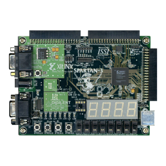
Chapter 1 Introduction The Xilinx Spartan-3 Starter Kit provides a low-cost, easy-to-use development and evaluation platform for Spartan-3 FPGA designs. Key Components and Features Figure 1-1 shows the Spartan-3 Starter Kit board, which includes the following components and features: •... - Page 8 Regulator Regulator 5 VDC, 2A Supply AC Wall Adapter 100-240V AC Input Included 50-60 Hz UG130_c1_01_042504 Figure 1-1: Xilinx Spartan-3 Starter Kit Board Block Diagram • PS/2-style mouse/keyboard port • Four-character, seven-segment LED display • Eight slide switches • Eight individual LED outputs •...
-
Page 9: Component Locations
Push button switch to force FPGA reconfiguration (FPGA configuration happens automatically at power-on) • LED indicates when FPGA is successfully configured • Three 40-pin expansion connection ports to extend and enhance the Spartan-3 Starter Kit Board ♦ www.xilinx.com/s3boards for compatible expansion cards ♦... - Page 10 XC3S200 DONE FPGA PROG POWER POWER PS/2 ug130_c1_02_042704 Figure 1-2: Xilinx Spartan-3 Starter Kit Board (Top Side) 2.5V 1.2V ug130_c1_03_042704 Figure 1-3: Xilinx Spartan-3 Starter Kit Board (Bottom Side) www.xilinx.com Spartan-3 Starter Kit Board User Guide 1-800-255-7778 UG130 (v1.1) May 13, 2005...
-
Page 11: Chapter 2: Fast, Asynchronous Sram
Chapter 2 Fast, Asynchronous SRAM The Spartan-3 Starter Kit board has a megabyte of fast asynchronous SRAM, surface- mounted to the backside of the board. The memory array includes two 256Kx16 ISSI IS61LV25616AL-10T 10 ns SRAM devices, as shown in Figure 2-1. -
Page 12: Address Bus Connections
2-1. These address signals also connect to the A1 Expansion Connector (see “Expansion Connectors,” page 47). Table 2-1: External SRAM Address Bus Connections to Spartan-3 FPGA Address Bit FPGA Pin A1 Expansion Connector Pin www.xilinx.com Spartan-3 Starter Kit Board User Guide 1-800-255-7778 UG130 (v1.1) May 13, 2005... -
Page 13: Write Enable And Output Enable Control Signals
2-2. These control signals also connect to the A1 Expansion Connector (refer to “Expansion Connectors,” page 47). Table 2-2: External SRAM Control Signal Connections to Spartan-3 FPGA Signal FPGA Pin A1 Expansion Connector Pin SRAM Data Signals, Chip Enables, and Byte Enables The data signals, chip enables, and byte enables are dedicated connections between the FPGA and SRAM. - Page 14 Table 2-4: SRAM IC11 Connections Signal FPGA Pin IO15 IO14 IO13 IO12 IO11 IO10 CE2 (chip enable IC11) UB2 (upper byte enable IC11) LB2 (lower byte enable IC11) www.xilinx.com Spartan-3 Starter Kit Board User Guide 1-800-255-7778 UG130 (v1.1) May 13, 2005...
-
Page 15: Chapter 3: Four-Digit, Seven-Segment Led Display
Chapter 3 Four-Digit, Seven-Segment LED Display The Spartan-3 Starter Kit board has a four-character, seven segment LED display controlled by FPGA user-I/O pins, as shown in Figure 3-1. Each digit shares eight common control signals to light individual LED segments. Each individual character has a separate anode control input. - Page 16 Segment FPGA Pin Table 3-2: Digit Enable (Anode Control) Signals (Active Low) Anode Control FPGA Pin Table 3-3: Display Characters and Resulting LED Segment Control Values Character www.xilinx.com Spartan-3 Starter Kit Board User Guide 1-800-255-7778 UG130 (v1.1) May 13, 2005...
- Page 17 I/O down to 12 pins. The drawback to this approach is that the FPGA logic must continuously scan data out to the displays—a small price to save 20 additional I/O pins. Spartan-3 Starter Kit Board User Guide www.xilinx.com UG130 (v1.1) May 13, 2005...
- Page 18 Chapter 3: Four-Digit, Seven-Segment LED Display www.xilinx.com Spartan-3 Starter Kit Board User Guide 1-800-255-7778 UG130 (v1.1) May 13, 2005...
-
Page 19: Chapter 4: Switches And Leds
Chapter 4 Switches and LEDs Slide Switches The Spartan-3 Starter Kit board has eight slide switches, indicated as Figure 1-2. The switches are located along the lower edge of the board, toward the right edge. The switches are labeled SW7 through SW0. Switch SW7 is the left-most switch, and SW0 is the right- most switch. -
Page 20: Leds
Chapter 4: Switches and LEDs LEDs The Spartan-3 Starter Kit board has eight individual surface-mount LEDs located above the push button switches, indicated by Figure 1-2. The LEDs are labeled LED7 through LED0. LED7 is the left-most LED, LED0 the right-most LED. -
Page 21: Chapter 5: Vga Port
Chapter 5 VGA Port The Spartan-3 Starter Kit board includes a VGA display port and DB15 connector, indicated as Figure 1-2. Connect this port directly to most PC monitors or flat-panel LCD displays using a standard monitor cable. Pin 5... -
Page 22: Signal Timing For A 60Hz, 640X480 Vga Display
Chapter 5: VGA Port Table 5-1: VGA Port Connections to the Spartan-3 FPGA Signal FPGA Pin Red (R) Green (G) Blue (B) Horizontal Sync (HS) Vertical Sync (VS) Each color line has a series resistor to provide 3-bit color, with one bit each for Red, Green, and Blue. - Page 23 The size of the beams, the frequency at which the beam traces across the display, and the frequency at which the electron beam is modulated determine the display resolution. Spartan-3 Starter Kit Board User Guide www.xilinx.com UG130 (v1.1) May 13, 2005...
-
Page 24: Vga Signal Timing
Video data typically comes from a video refresh memory with one or more bytes assigned to each pixel location. The Spartan-3 Starter Kit board uses three bits per pixel, producing one of the eight possible colors shown in Table 5-2. - Page 25 No time relationship is specified between the onset of the HS pulse and the onset of the VS pulse. Consequently the counters can be arranged to easily form video RAM addresses, or to minimize decoding logic for sync pulse generation. Spartan-3 Starter Kit Board User Guide www.xilinx.com UG130 (v1.1) May 13, 2005...
- Page 26 Chapter 5: VGA Port www.xilinx.com Spartan-3 Starter Kit Board User Guide 1-800-255-7778 UG130 (v1.1) May 13, 2005...
-
Page 27: Chapter 6: Ps/2 Mouse/Keyboard Port
Both a PC mouse and keyboard use the two-wire PS/2 serial bus to communicate with a host device, the Spartan-3 FPGA in this case. The PS/2 bus includes both clock and data. Both a mouse and keyboard drive the bus with identical signal timings and both use 11-bit words that include a start, stop and odd parity bit. -
Page 28: Keyboard
When an extended key is released, a “E0 F0” key- up code is sent, followed by the scan code. www.xilinx.com Spartan-3 Starter Kit Board User Guide 1-800-255-7778 UG130 (v1.1) May 13, 2005... - Page 29 When the keyboard sends data, it generates 11 clock transitions at around 20 to 30 kHz, and data is valid on the falling edge of the clock as shown in Figure 6-2. Spartan-3 Starter Kit Board User Guide www.xilinx.com UG130 (v1.1) May 13, 2005 1-800-255-7778...
-
Page 30: Mouse
The XV and YV bits in the status byte indicate when the X or Y values exceed their maximum value, an overflow condition. A ‘1’ indicates www.xilinx.com Spartan-3 Starter Kit Board User Guide 1-800-255-7778 UG130 (v1.1) May 13, 2005... -
Page 31: Voltage Supply
Some older keyboards and mice are 5V only. Consequently, the JP2 jumper should be set for 5V operation as shown in Table 6-5. The Spartan-3 FPGA can tolerate 5V signals due to the 270Ω series resistors on the PS/2 data and clock signals connected to the FPGA. See the schematic in Figure A-7 for more details. - Page 32 Chapter 6: PS/2 Mouse/Keyboard Port www.xilinx.com Spartan-3 Starter Kit Board User Guide 1-800-255-7778 UG130 (v1.1) May 13, 2005...
- Page 33 Chapter 7 RS-232 Serial Port The Spartan-3 Starter Kit board has an RS-232 serial port. The RS-232 transmit and receive signals appear on the female DB9 connector, labeled J2, indicated as Figure 1-2. The connector is a DCE-style port and connects to the DB9 DTE-style serial port connector available on most personal computers and workstations.
-
Page 34: Chapter 7: Rs-232 Port
7-1. Similarly, the port’s RTS and CTS signals connect together. The FPGA connections to the Maxim RS-232 translator appear in Table 7-1. Table 7-1: Accessory Port Connections to the Spartan-3 FPGA Signal FPGA Pin RXD-A TXD-A An auxiliary RS-232 serial channel from the Maxim device is available on two 0.1-inch... -
Page 35: Chapter 8: Clock Sources
Chapter 8 Clock Sources The Spartan-3 Starter Kit board has a dedicated 50 MHz Epson SG-8002JF series clock oscillator source and an optional socket for another clock oscillator source. Figure A-5 provides a detailed schematic for the clock sources. The 50 MHz clock oscillator is mounted on the bottom side of the board, indicated as Figure A-5. -
Page 36: Chapter 9: Fpga Configuration Modes And Functions
Functions FPGA Configuration Mode Settings In most applications for the Spartan-3 Starter Kit Board, the FPGA automatically boots from the on-board Platform Flash memory whenever power is applied or the PROG push button is pressed. However, the board supports all the available configuration modes via... -
Page 37: Program Push Button/Done Indicator Led
<1:0:1> M0 M1 M2 Program Push Button/DONE Indicator LED The Spartan-3 Starter Kit Board includes two FPGA configuration functions, located near the VGA connector and the AC power input connector, as shown in Figure 9-1. The PROG push button, shown as Figure 9-1, drives the FPGA’s PROG_B programming pin. -
Page 38: Chapter 10: Platform Flash Configuration Storage
Chapter 10 Platform Flash Configuration Storage The Spartan-3 Starter Kit board has an XCF02S serial configuration Flash PROM to store FPGA configuration data and potentially additional non-volatile data, including MicroBlaze application code. To configure the FPGA from Platform Flash memory, all... -
Page 39: Flash Read" Option
Figure 10-1: Default Platform Flash Option “Flash Read” Option The Spartan-3 Starter Kit Board includes a 2Mbit Platform Flash configuration PROM. The XC3S200 FPGA on the board only requires slightly less than 1Mbit for configuration data. The remainder of the Platform Flash is available to store other non-volatile data, such as revision codes, serial numbers, coefficients, an Ethernet MAC ID, or code for an embedded processor, such as MicroBlaze, within the FPGA. -
Page 40: Disable" Option
“Disable” Option If the JP1 jumper is removed, then the Platform Flash is disabled, potentially allowing configuration via an expansion board connected to one of the expansion connectors. www.xilinx.com Spartan-3 Starter Kit Board User Guide 1-800-255-7778 UG130 (v1.1) May 13, 2005... -
Page 41: Chapter 11: Jtag Programming/Debugging Ports
JTAG Programming/Debugging Ports The Spartan-3 Starter Kit board includes a JTAG programming and debugging chain. Both the Spartan-3 FPGA and the Platform Flash devices are part of the JTAG chain, as shown in Figure 11-1. Additionally, there are two JTAG headers for driving the JTAG signals from various supported JTAG download and debugging cables. -
Page 42: Parallel Cable Iv/Multipro Desktop Tool Jtag Header (J5)
Spartan-3 Starter Kit board only supports the JTAG configuration method. The header is designed for a keyed socket. However, the Spartan-3 Starter Kit uses only stake pins. The outline of the keyed connector appears around the J5 header, as shown in Figure 11-3. - Page 43 Notch on outline JTAG matches key on header UG130_c11_03_042704 Figure 11-3: Use 14-Pin Ribbon Cable to Connect Parallel Cable IV or the MultiPro Desktop Tool to the J5 Header Spartan-3 Starter Kit Board User Guide www.xilinx.com UG130 (v1.1) May 13, 2005 1-800-255-7778...
- Page 44 Chapter 11: JTAG Programming/Debugging Ports www.xilinx.com Spartan-3 Starter Kit Board User Guide 1-800-255-7778 UG130 (v1.1) May 13, 2005...
-
Page 45: Chapter 12: Power Distribution
The AC wall adapter operates from 100V to 240V AC input, at 50 or 60 Hz. Voltage Regulators There are multiple voltages supplied on the Spartan-3 Starter Kit Board, as summarized in Table 12-1. - Page 46 Spartan-3 FPGAs. Figure A-3 provides a detailed schematic of the various voltage regulators. Similarly, Figure A-6 shows the power decoupling capacitors. www.xilinx.com Spartan-3 Starter Kit Board User Guide 1-800-255-7778 UG130 (v1.1) May 13, 2005...
-
Page 47: Chapter 13: Expansion Connectors And Boards
Chapter 13 Expansion Connectors and Boards Expansion Connectors The Spartan-3 Starter Kit board has three 40-pin expansion connectors labeled A1, A2, and B1. The A1 and A2 connectors, indicated as , respectively, in Figure 1-2, are on the top edge of the board. Connector A1 is on the top left, and A2 is on the top right. The B1... - Page 48 √ √ Each port offers some ability to program the FPGA on the Spartan-3 Starter Kit Board. For example, port A1 provides additional logic to drive the FPGA and Platform Flash JTAG chain. Similarly, ports A2 and B1 provide connections for Master or Slave Serial mode configuration.
-
Page 49: A1 Connector Pinout
SRAM A15 MA1-INT (L3) JTAG Isolation JTAG Isolation SRAM A17 (C13) (C14) FPGA JTAG TMS FPGA JTAG TCK TDO-ROM Platform Flash Header J7, pin 3 TDO-A JTAG TDO Spartan-3 Starter Kit Board User Guide www.xilinx.com UG130 (v1.1) May 13, 2005 1-800-255-7778... -
Page 50: A2 Connector Pinout
MA2-INT/GCK4 (D9) (B3) PROG-B Oscillator socket FPGA PROG_B DONE (R14) (N9) INIT FPGA DONE FPGA INIT_B CCLK (T15) (M11) FPGA CCLK Connects to (A14) via 390Ω resistor www.xilinx.com Spartan-3 Starter Kit Board User Guide 1-800-255-7778 UG130 (v1.1) May 13, 2005... -
Page 51: B1 Connector Pinout
(K15) MB1-RESET MB1-INT (L15) (B3) PROG-B FPGA PROG_B DONE (R14) (N9) INIT FPGA DONE FPGA INIT_B CCLK (T15) (M11) FPGA CCLK Connects to (A14) via 390Ω resistor Spartan-3 Starter Kit Board User Guide www.xilinx.com UG130 (v1.1) May 13, 2005 1-800-255-7778... -
Page 52: Expansion Boards
• Digilent Breakout Probe Header (TPH1) https://digilent.us/Sales/Product.cfm?Prod=TPH1 • Digilent Breadboard (DBB1) https://digilent.us/Sales/Product.cfm?Prod=DBB1 • Digilent Wire-wrap Board (DWR1) https://digilent.us/Sales/Product.cfm?Prod=DWR1 • Digilent SPP, EPP, ECP Parallel Port (PIO1) https://digilent.us/Sales/Product.cfm?Prod=PIO1 www.xilinx.com Spartan-3 Starter Kit Board User Guide 1-800-255-7778 UG130 (v1.1) May 13, 2005... -
Page 53: Appendix A: Board Schematics
Appendix A Board Schematics This appendix provides the schematics for the Spartan-3 Starter Kit Board: • Figure A-1, “A1, A2, and B1 Expansion Connectors” • Figure A-2, “Slide Switches, Push Buttons, LEDs, and Four-Character 7-Segment Display” • Figure A-3, “Voltage Regulators, JP2 Jumper Setting for PS/2 Port Voltage”... - Page 54 NOTE: SRAM address lines and OE#, WE# controls have shared connections with A1 connector. Likewise, lower eight data bits to SRAM IC10 are also shared with A1 connector.
- Page 61 NOTE: SRAM address lines and OE#, WE# controls have shared connections with A1 connector. Likewise, lower eight data bits to SRAM IC10 are also shared with A1 connector.
-
Page 63: Appendix B: Reference Material For Major Components
Appendix B Reference Material for Major Components Table B-1 lists the major components on the Spartan-3 Starter Kit Board, including full part numbers and links to complete device data sheets. Table B-1: Major Components and Data Sheet Links Device Vendor... - Page 64 PN 0402292 www.xilinx.com Spartan-3 Starter Kit Board User Guide 1-800-255-7778 UG130 (v1.1) May 13, 2005...
- Page 65 Mouser Electronics Authorized Distributor Click to View Pricing, Inventory, Delivery & Lifecycle Information: Digilent 410-044P-KIT 410-044...
Need help?
Do you have a question about the Spartan-3 and is the answer not in the manual?
Questions and answers