
Summary of Contents for Hatteras HN4000
- Page 1 HN4000 Hardware Installation Guide Copyright© 2004‐2008 by Hatteras Networks Inc. All Rights Reserved Printed in the United States of America Rev 14, May 30, 2008 Ordering No. 920550‐5020 Rev 14...
- Page 2 RANTIES WHICH EXTEND BEYOND THE DESCRIPTIONS CONTAINED IN THIS PARAGRAPH. NO WAR- RANTY MAY BE CREATED OR EXTENDED BY SALES REPRESENTATIVES OR WRITTEN SALES MATERIALS. HATTERAS NETWORKS SHALL NOT BE LIABLE FOR ANY LOSS OF PROFIT OR ANY OTHER COMMERCIAL DAMAGES, INCLUDING BUT NOT LIMITED TO SPECIAL, INCIDENTAL, CONSEQUENTIAL, OR OTHER DAMAGES.
- Page 3 Revision 08 ‐ July 7, 2006 Change bars mark changes from the 07 revision of the document. Updated power and heat specifications in the Technical Specifications Revision 07 ‐ April 17, 2006 appendix. Change bars mark cumulative changes from the 05 revision of the document. Added information about unchannelized T3/E3‐TX high‐speed module Revision 06 ‐ March 1, 2006 supporting x.86 and GFP. Change bars mark changes from the 05 revision of the document. Added Class 1 laser warning and updated Hatteras Network’s shipping Revision 05 ‐ January 13, 2006 address. Change bars indicate cumulative changes from document revision 03. Added information about HN4000i unit. Updated software installation Revision 04 December 2, 2005 examples to reflect 4.5.0 CLI commands. Added information about available SFP transceivers. Change bars mark changes from the 03 revision of the document. Updated software installation examples to reflect 3.6.0 CLI commands. Revision 03 June 3, 2005 Added information about HN4000 label. Change bars mark cumulative changes from the 01 and 02 revisions of the document. Updated photos and installation descriptions to reflect new‐style 23” Revision 02 January 31, 2005 ANSI mounting brackets. Change bars mark changes from the 01 revision of the document. Minor technical and editing updates. Revision 01 November 23, 2004 Original document Revision 00 September 30, 2004...
-
Page 5: Table Of Contents
1.2 - HN4000 Metro Ethernet Copper Access Switch Overview ....... . - Page 6 5.2.1 - Connect the HN4000 Switch to the DHCP Network .......
- Page 7 E.1 - Hatteras Networks Technical Support Center ........
- Page 8 Contents HN4000 Hardware Installation Guide 920550-5020 Rev 14...
-
Page 9: List Of Figures
Figure 2-2 - HN4000 Chassis Showing Bracket Orientation ....... . . - Page 10 Figure 5-4 - Specifying an IP Address for the HN4000 MAC Address......
-
Page 11: List Of Tables
Table 1-2 - HN4000 High-Speed Module Model Numbers ....... . . - Page 12 List of Tables HN4000 Hardware Installation Guide 920550-5020 Rev 14...
-
Page 13: Overview
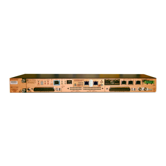
Ethernet Copper Access™ switch. There are two switch models in the HN4000 product line — the HN4000i and the HN4000e (Figure 1‐1). Figure 1-1 Front View of the HN4000 Switches (HN4000i Top and HN4000e Bottom) When this document uses the term HN4000, the discussion applies to both switch models — the Note HN4000e and the HN4000i. 1.1.1 Objectives This document is for installation technicians who will install an HN4000 switch at a Central ... -
Page 14: Hn4000 Metro Ethernet Copper Access Switch Overview
HN4000 Metro Ethernet Copper Access Switch Overview HN4000 Metro Ethernet Copper Access Switch Overview The HN4000 Metro Ethernet Copper Access switches are full featured high‐performance access devices that deliver integrated voice, data, and video services based on Ethernet access over voice‐grade copper pairs. The HN4000 switches provide the following features: ❒ Mounts in a standard 19 inch, 23 inch, or 600 mm rack or cabinet ❒ Front‐panel accessible ‐ no rear clearance required for side‐exhaust models ❒ Dual‐feed power connectors — powered from one or two ‐48 VDC power sources. ❒ 40 pairs of 2BASE‐TL per switch (IEEE 803.3ah standard for Ethernet transport over G.SHDSL) ❒ Support for the Extended‐Rate Single‐Pair High‐Speed Digital Subscriber Line (E‐SHDSL) transmission technology ❒ Modular high‐speed network interfaces ❒ NEBS Level 3/ETSI certified ❒ In‐band and out‐of‐band Network Management ❒ Dual versions of the system software on the switch The TDR-Enabled HN4000e Switches In addition to the HN4000 features described above, the HN4000e switches provide the follow‐... -
Page 15: Figure 1-2 Hn4000 Equipment With Hn4Xx-Cp Devices
❒ HN418‐U‐2E‐I — eight‐pair universal device operating in CP mode ‐ this device is pro‐ vided with one optical 100BASE‐X network interface and one 10/100 Mbps BASE‐TX net‐ work interface This document uses the term “HN4xx-CP” to refer to Hatteras Networks CP devices or universal Note devices operating in CP mode. Figure 1-2 HN4000 Equipment With HN4xx-CP Devices 920550-5020 Rev 14 HN4000 Hardware Installation Guide... -
Page 16: Hn4000 Main Chassis
Main chassis Figure 1-3 Annotated Front View of HN4000 Equipment (HN4000e Shown) 1.3.1 HN4000 Main Chassis The HN4000 main chassis is the power source for the circuit cards and the HN4000 Cooling Unit. Table 1-1 HN4000 Main Chassis Size and Weight HN4000 Main Chassis Dimensions Height: 1.72” (44 mm) -
Page 17: High-Speed Network Modules
HN4000 Metro Ethernet Copper Access Switch Overview 1.3.3 High-Speed Network Modules An HN4000 can be configured with one of the pluggable high‐speed network modules shown in Figure 1‐4 and described in Table 1‐2. The high‐speed modules plug into the Universal I/O Slot. Figure 1-4 High-Speed Network Modules Table 1-2 HN4000 High-Speed Module Model Numbers Description Model Number • Dual 100/1000BASE‐T Ethernet ports HN4000‐GbT • Dual 1000BASE‐X small form‐factor pluggable (SFP) Ethernet ports HN4000‐GbX • Dual 100BASE‐X small form‐factor pluggable (SFP) Ethernet ports HN4000‐FEX • Unchannelized T3/E3‐TX port supporting x.86 and GFP HN4000‐TE3 920550-5020 Rev 14... -
Page 18: Site Requirements And Recommendations
Table 1‐4 lists the installation clearances for the HN4000 equipment. The clearanced areas must provide for a free flow of air. Table 1-4 HN4000 Installation Clearances Area HN4000 Side-Exhaust Model HN4000 Rear-Exhaust Model Clearances Clearances Rear Flush 4” (100 mm) Front > 3” (> 75 mm) > 3” (> 75 mm) Right Side (Facing Unit) 4” (100 mm) Flush Left Side (Facing Unit) 4” (100 mm) 4” (100 mm) Top and Bottom Flush Flush See Appendix C for a complete list of HN4000 technical specifications. HN4000 Hardware Installation Guide 920550-5020 Rev 14... -
Page 19: Rack Considerations
Power port Fuse Panel Power cables (14 ‐ 18 AWG (1.6 ‐ 1.0 mm)) Ground lug Customer Defined Ground cable (10 ‐ 14 AWG (2.6 ‐ 1.6 mm)) Dual 100/1000BASE‐T Customer Defined CAT‐5e shielded cable High‐Speed Ethernet Module** Dual 100BASE‐X or Dual Customer Defined Fiber optic cable 1000BASE‐X High‐Speed Ethernet Module 2BASE‐TL ports Customer Defined 25‐pair CAT‐5 24 AWG shielded cable CBL100‐0010‐11 10 feet (3.0m) CBL102‐0025‐12 25 feet (7.6 m) CBL102‐0050‐12 50 feet (15.2m) CBL102‐0100‐12 100 feet (30.5m) 10/100 MGMT port** Customer Defined CAT‐5e shielded cable Alarm port** Customer Defined CAT‐5e shielded cable CBL100‐0010‐11 920550-5020 Rev 14 HN4000 Hardware Installation Guide... - Page 20 Stacking cables must be provided by Hatteras Networks. b. The following Cisco Systems “Cisco Blue Console Cables” can be used to connect a laptop to the RJ‐45 craft port: 72‐3383‐01 cable or 72‐1259‐01 cable with 74‐0495‐01 adapter. (This cable is not shielded and must not be used for permanent installation.) Intra-Building Port Warning The following HN4000 ports are suitable for connection to intrabuilding or unexposed wiring or cabling only: • 100/1000BASE-T high-speed uplink port • 10/100 MGMT management port • Alarm port • RS-232 console port •...
-
Page 21: Power And Ground Requirements
Ground and Power Cables” on page 2‐6 for installation information. The DC return is to remain isolated from the system frame and the chassis (DC-I). Note 1.7.3 Grounding Requirements The HN4000 must be permanently grounded to a Common Bonding Network (CBN). Caution The HN4000 chassis is equipped with a double‐hole crimped terminal. Grounding of the raw end of the cable should conform with local practices, using wire sizes of 10‐14 AWG (1.6‐2.6 mm). Refer to the section ”Installing the Ground and Power Cables” on page 2‐6 for installation ... -
Page 22: Hn4000 Model Number Information
1-10 HN4000 Model Number Information HN4000 Model Number Information An HN4000’s model number and revision letter information is printed on the product label located at the rear of the switch, as shown in the following example. HN4000 Revision Level HN4000 Part Number You can also display HN4000 model number and revision level by using the CLI “show switch n” command, where “n” is a switch number. Use the number “1” for a standalone switch. In the “show switch” display, the “partNum” field displays the HN4000 part number and the “partNumRev” field displays the switch’s revision level. Note that revision letters (starting with “A”) were introduced in early 2005. HN4000 switches shipped prior to that used an inte‐ ger number in the “partNumRev” field. Refer to Table B.1 on page B‐1 for model number information. HN4000 Hardware Installation Guide 920550-5020 Rev 14... -
Page 23: Safety Information
This device contains connectors for two power sources. Disconnect all power sources before servicing. Caution ‐ Lifting Although installation of the HN4000 can be accomplished by one installation technician, care should be taken to prevent injury while lifting any equipment. Caution . . . . . . . . 920550-5020 Rev 14... - Page 24 1-12 Safety Information HN4000 Hardware Installation Guide 920550-5020 Rev 14...
-
Page 25: Installing The Hn4000 Switch
Installing the HN4000 Switch Unpacking and Inventory Each HN4000 includes individually packaged components that must be inventoried to verify that all components have been received. Static Electricity can damage or decrease the reliability of electrical and optical equipment. While unpacking and handling electrical and optical equipment, wear a grounding wrist strap to dis- charge the static buildup. The grounding wrist strap is designed to prevent equipment damage caused by static electricity. -
Page 26: Installing The Hn4000 Equipment
Figure 2-1 HN4000 Switch as Delivered (HN4000e Shown) Installation of the HN4000 equipment follows the steps outlined below: ❒ Installing the mounting brackets ❒ Installing the HN4000 in a rack ❒ Installing the power and ground cables ❒ Powering up the device Do not operate an HN4000 without its fan-module cooling unit installed. Caution HN4000 Hardware Installation Guide 920550-5020 Rev 14... -
Page 27: Installing The Rack Mounting Brackets
Installing the Rack Mounting Brackets 2.4.1 Bracket Orientation To ensure proper mounting‐bracket installation, the HN4000 chassis is stamped “Right” and “Left” in the bracket mounting areas. In addition, the mounting brackets are stamped “Right” and “Left.” Figure 2‐2 shows the stamping on the right side of the chassis (highlighted). Note that the right‐ and left‐side chassis stampings are relative to viewing the chassis from the front. Front of Chassis Right-Side Stamping Right-Side Bracket with Cable- Guide Slots (ANSI 19” Shown) Figure 2-2 HN4000 Chassis Showing Bracket Orientation 920550-5020 Rev 14 HN4000 Hardware Installation Guide... -
Page 28: Mounting Brackets And Hardware
23” ANSI Mounting Hardware 600 mm ETSI Mounting Hardware Figure 2-3 Bracket Assemblies and Hardware The contents of the kits are: 1. 19” ANSI rack mounting — a mounting kit with two brackets, eight #6‐32 bracket screws, four #12‐24 rack screws, and four #12 external‐tooth lock washers (shown at the left side of Figure 2‐3). 2. 23” ANSI rack mounting — the contents of the 19” ANSI rack mounting kit (described above), plus two 23” ANSI extender brackets, four #12‐24 rack screws, and four #12 exter‐ nal‐tooth lock washers. The kit is shown in the center of Figure 2‐3.) Note that the four screws and washers for the extender brackets are packaged in the 19” ANSI kit’s hardware bag. The 23” ANSI mounting kit is provided if no mounting type is specified when an HN4000 is ordered. 3. 600 mm wide ETSI rack/cabinet mounting — a mounting kit with eight #6‐32 bracket screws, four M6 rack screws, and four M6 external‐tooth lock washers (shown at the right side of Figure 2‐3). HN4000 Hardware Installation Guide 920550-5020 Rev 14... -
Page 29: Assembling The Brackets
Step 2. Tighten the Phillips head screws to 6 ‐ 10 in‐lbs (0.7 ‐ 1.1 Nm). Figure 2‐4 shows an ANSI 19” bracket mounted on the right side of a chassis. Figure 2-4 Right-Side ANSI 19” Bracket Step 3. If the HN4000 is to be installed in a 23” ANSI rack, take steps 3a‐through‐3c below. Otherwise, go to Step 4. Referring to Figure 2‐5, orient the end of an extender bracket with the drilled and tapped holes behind the left‐side 19” ANSI bracket. Note that the extender bracket’s offset is toward the front of the HN4000. Left-Side 19” Bracket Extender Extender Bracket Bracket Right-Side 19” Bracket Figure 2-5 Orientation of Extender Brackets 920550-5020 Rev 14 HN4000 Hardware Installation Guide... -
Page 30: Installing The Hn4000 Chassis In The Rack
Caution Follow ESD procedures per local practice. Always use a wrist strap attached to the ESD ground Figure 2‐6 jack located on the lower left side of the HN4000 chassis ( ESD Jack Figure 2-6 ESD Jack Location... -
Page 31: Connecting A Chassis Ground Cable
Take the following steps to connect a ground cable from the HN4000 chassis to an earth ground. The HN4000 must be permanently grounded to a Common Bonding Network (CBN). Grounding of the HN4000 should be in compliance with local practices and must be to a protective earth ground (clean, bare-metal). Caution The grounding connection must be made before copper-pair connections are made to the device’s 2BASE-TL connectors. -
Page 32: Connecting -48 Vdc Power
Take the following steps to install and connect a ‐48 VDC power source (or sources) to an HN4000. Step 1. If the panel providing the ‐48 VDC source is equipped with a circuit breaker, move the breaker to the OFF position. If the panel is equipped with a fuse, remove the assigned fuse. Step 2. Referring to Figure 2‐8, take the following steps to connect the ‐48 VDC cable to the provided 4‐pin power plug. HN4000 power conductors must be 14 - 18 AWG (1.6 - 1.0 mm) copper wire. Note a. Strip approximately 1/8” (0.32cm) of insulation from the ‐48 VDC cable’s two leads and tin them. b. Insert the tinned end of the cable’s ‐48 VDC lead into pin 1 of the 4‐pin power plug. Tighten the pin’s clamping screw with a 1/8” flat‐blade screwdriver. (This lead will connect to the “A ‐48” pin of the HN4000’s power connector.) c. Insert the tinned end of the cable’s return (RTN) lead into pin 2 of the 4‐pin power plug and tighten the pin’s clamping screw. (This lead will connect to the “A RTN” pin of the HN4000’s power connector.) Figure 2‐8 Power Plug Connections for Single (“A”) and Dual (“A” and “B”) Power Sources... -
Page 33: Hn4000 4-Pin Power Plugs
Figure 2-9 Example of a Single Power Connection 2.6.3 HN4000 4-pin Power Plugs The 4-pin power plugs used with the HN4000 are manufactured by Phoenix Contact (P/N 1777824). They are available at distributors such as Mouser (www.mouser.com Note P/N 651-1777824), as well as other distributors such as Future Electronics, Sager Electronics, and TTI. -
Page 34: Powering Up The Hn4000
2-10 Powering Up the HN4000 Powering Up the HN4000 Take the following steps to power up the HN4000 and verify basic operation. Step 1. Switch the power source’s ‐48 VDC breaker to the On position (or replace the fuse if one was removed in Step 1). Step 2. Verify that the device’s Power A LED is on. Step 3. [Optional] If a second power source is connected to the device, verify that the Power B LED is also on. When power is applied to the device, the device automatically starts its power‐up sequence. Figure 2‐10 shows the status of the POWER and SYSTEM LEDs during the power‐up sequence. Figure 2-10 Power-Up LED Sequence At the end of a successful power‐up sequence: ❒ the POWER LED for the A or B power connection will be on (or both LEDs will be on if two power sources are connected) ❒ the SYSTEM OK LED will be on ❒ the SYSTEM FAIL LED will be off HN4000 Hardware Installation Guide... -
Page 35: Verifying Fan-Module Operation
Verifying Fan-Module Operation After the HN4000 powers up, verify that Cooling Unit Fail LED is “off,” indicating that the fan module is operating. Figure 2‐11 shows the LED’s location. Figure 2-11 Cooling Unit Module and Cooling Unit Failure Indicator Do not operate an HN4000 for more than two minutes without its fan-module operating. Caution End of Procedure 920550-5020 Rev 14 HN4000 Hardware Installation Guide... -
Page 36: Verifying Led Operation - Lamp Test
Verifying LED Operation - Lamp Test Verifying LED Operation - Lamp Test Use the following procedure to verify that the LEDs on the HN4000 chassis and high‐speed network module are operating properly. Step 1. Press and hold the LAMP TEST button for approximately 2 seconds (Figure 2‐12). Figure 2-12 Lamp Test Button Step 2. Verify that all LEDs on the HN4000 chassis and high‐speed network module are on. Step 3. Release the LAMP TEST button. End of Procedure . . . . . . . . HN4000 Hardware Installation Guide 920550-5020 Rev 14... -
Page 37: Front Panel Features
Port 2BASE-TL and bonded 2BASE-TL Figure 3-1 Device Ports and LEDs (HN4000e Shown) Power Connector and Power LEDs Figure 3‐2 shows a detail of the HN4000 device’s power connector and power LEDs. Power Source “A” Power “B” Power LEDs Figure 3-2 -48 VDC Power Connector 920550-5020 Rev 14 HN4000 Hardware Installation Guide... -
Page 38: Power Connector
Power Connector and Power LEDs 3.1.1 Power Connector The HN4000 can be powered from one or two ‐48 VDC power sources. If two power sources are used, the device will continue to operate normally should one of the sources fail. The power connector has four pins ‐ two pins for each of the two ‐48 VDC power sources that can be connected to the device. As shown in Figure 3‐2 on page 3‐1, the pins are (from left to right): ❒ Pin 1 ‐ “A” power source negative (‐) connection ❒ Pin 2 ‐ “A” power source positive (+) connection ❒ Pin 3 ‐ “B” power source negative (‐) connection ❒ Pin 4 ‐ “B” power source positive (+) connection 3.1.2 Power Status LEDs There are two power status LEDs: “A” and “B.” ❒ “A” LED ‐ On (steady green) when ‐48 VDC is detected at the “A” connections (pins 1 and 2) ❒ “B” LED ‐ On (steady green) when ‐48 VDC is detected at the “B” connections (pins 3 and 4) Note that at least one of the power status LEDs must be on for the device to be operational. Both power status LEDs will be on when two operational power sources power are connected. HN4000 Hardware Installation Guide 920550-5020 Rev 14... -
Page 39: System Status Leds
Description Marking MASTER Device is not the master when it is part of a stack. Device is the master when it is part of a stack (the default for a standalone HN4000). COOLING Cooling Unit is operating properly. UNIT FAIL One or more of the cooling fans are not operating, or no Cooling Unit is installed. CHASSIS 1, 2, 3, ... The chassis number of the HN4000 when it is part of a stack. (Always 1 for a standalone HN4000.) Device is not receiving power or has not finished self‐test. Blinking Green Device is receiving power and is performing self‐test operations. Steady Green Device has completed self‐test and is ready to pass traffic (normal operation) FAIL If device is powered on (OK LED steady green), no hardware failures are detected (normal operation). On power‐up, indicates that the device is performing self‐test. After self‐test has run, indicates that the device has detected a hardware failure. ALARMS The HN4000 is currently reporting no critical alarms. CRITICAL The HN4000 has detected one or more critical alarms. ALARMS The HN4000 is currently reporting no major alarms. MAJOR The HN4000 has detected one or more major alarms. 920550-5020 Rev 14 HN4000 Hardware Installation Guide... -
Page 40: Lamp Test Button
Figure 3-4 Lamp Test Button In releases of the system software prior to release 5.0.0, all three lamp test operations are Note enabled. 3.3.1 Testing the Device’s Lamps ❒ If you press and hold the LAMP TEST button for less than two seconds, all of the device’s LEDs will illuminate while the button is pressed. ❒ If you press and hold the button for more than two seconds but less than five seconds, the LEDs return to normal operation. HN4000 Hardware Installation Guide 920550-5020 Rev 14... -
Page 41: Resetting The Alarm Port
When the device is rebooted following a switch numbering change in switch-ID mode, any system-startup information in the device’s startup configuration file will be lost and data and man- agement traffic will be interrupted. Caution 920550-5020 Rev 14 HN4000 Hardware Installation Guide... -
Page 42: Rebooting The Device
10/100 Management Port and LEDs The HN4000 connects to a network management network through the 10/100 Mbps Manage‐ ment (MGMT) port (Figure 3‐6). Figure 3-6 10/100 Mbps Management Port Table 3‐2 describes the management port’s two status LEDs (LINK and ACT). Table 3-2 HN4000 Status LEDs LED State Description Marking No connection has been detected between the 10/100 Mbps port and a network LINK device. Solid Green A communication link has been established between the 10/100 Mbps port and a network device (normal operation). No traffic is being sent or received on the 10/100 Mbps port. Blinking Green Blinks as traffic passes through the port. HN4000 Hardware Installation Guide 920550-5020 Rev 14... -
Page 43: High-Speed Module Ports And Leds
High-Speed Module Ports and LEDs High-Speed Module Ports and LEDs The HN4000 connects to a carrier’s WAN through one of the pluggable high‐speed network modules listed in Table 3‐3. Table 3-3 HN4000 High-Speed Module Model Numbers Item Description Model Number • Dual 100/1000BASE‐T Ethernet ports Modules for HN4000 HN4000‐GbT Universal I/O Slot • Dual 1000BASE‐X small form‐factor pluggable (SFP) Ethernet ports HN4000‐GbX • Dual 100BASE‐X small form‐factor pluggable (SFP) Ethernet ports HN4000‐FEX • Unchannelized T3/E3‐TX port supporting x.86 and GFP HN4000‐TE3 The fiber‐optic modules have LINK and ACT (activity) LEDs for each of their two ports. The 100/1000BASE‐T copper module has LINK and ACT LEDS as well as a “1000” LED for each port to indicate a 1000 Mbps connection (Figure 3‐7). Figure 3-7 100/1000BASE-T High-Speed Module LEDs... -
Page 44: Figure 3-8 T3/E3-Tx High-Speed Module Leds
(All modules) Blinking Green Blinks as traffic passes through the port. 1000 Port is operating at 100 Mbps. (100/1000BASE-T modules only) Solid Green Port is in T3 (DS‐3) mode. (T3/E3-TX modules only) Solid Green Port is in E3 mode. (T3/E3-TX modules only) FR SYNC Solid Green The DS‐3/E‐3 framer is in sync. (T3/E3-TX modules only) LP BACK Solid Green The device’s line interface is looped back. (T3/E3-TX modules only) HN4000 Hardware Installation Guide 920550-5020 Rev 14... -
Page 45: 2Base-Tl Connectors And Leds
2BASE-TL Connectors and LEDs The HN4000 connects to the outside voice‐grade copper plant through two 2BASE‐TL 50‐pin RJ‐21 (“Champ”) connectors (Figure 3‐9): ❒ connector J1 supports 2BASE‐TL pairs 1‐16 ❒ connector J2 supports 2BASE‐TL pairs 17‐40 Connector J1 Pairs 1-16 Pairs 17-40 Connector J2 Figure 3-9 HN4000 2BASE-TL Connectors and LEDs The HN4000 has one status LED for each 2BASE‐TL pair. Table 3‐5 describes the LEDs’ operation. Table 3-5 2BASE-TL Status LEDs LED State Description Marking PAIRS 1-40 The numbered port has no copper pair attached. Or, if there is a copper pair attached, the numbered port and the associated port at the CP have not yet started to train. Steady Green The copper pair attached to the numbered port has trained with the associated ... -
Page 46: Metallic Loop Test Ports
3-10 Metallic Loop Test Ports Metallic Loop Test Ports The HN4000 provides external test access via two RJ‐45 jacks labeled “IN” and “OUT” (Figure 3‐10). You can use the CLI’s config mlt command to configure 2BASE‐TL ports for MLT testing and the show mlt command to display the results of a loopback test. Figure 3-10 Metallic Loop Test Ports Alarm Port The HN4000 Alarm I/O port (Figure 3‐11) is an RJ‐45 connector that provides an interface for alarms that the device generates, as well as supporting an input for external alarms. Alarms generated by the HN4000 are available on the Alarm port’s normally‐open and nor‐ mally‐closed relay contacts. Figure 3-11 Alarm Port HN4000 Hardware Installation Guide 920550-5020 Rev 14... -
Page 47: Stack Ports
3-11 Stack Ports 3.10 Stack Ports The HN4000’s Stack Ports (Figure 3‐12) are used to connect HN4000 devices to create an HN4000 Virtual Node (HN4000VN). From the user/network point‐of‐view, a stack appears as a single switch, which can be managed via a single IP address. Two‐to‐five HN4000s can be con‐ nected to create an HN4000 stack. Figure 3-12 Stack Ports . . . . . . . . 920550-5020 Rev 14 HN4000 Hardware Installation Guide... - Page 48 3-12 Stack Ports HN4000 Hardware Installation Guide 920550-5020 Rev 14...
-
Page 49: Connecting Hn4000 Cabling
Connecting HN4000 Cabling The HN4000 uses various types of cabling. Figure 4‐1 shows the general cable dressing guidelines for a typical installation. Figure 4-1 HN4000 Preferred Cable Routing 920550-5020 Rev 14 HN4000 Hardware Installation Guide... -
Page 50: Cabling The 10/100 Management Port
Cabling the 10/100 Management Port Cabling the 10/100 Management Port Cabling to the 10/100 management port is optional, depending on how the HN4000 will be managed. Note The “10/100 MGMT” port on the HN4000 is cabled to a customer Data Communication Network (DCN). -
Page 51: Cabling A High-Speed Network Module
Cabling a High-Speed Network Module Cabling a High-Speed Network Module The HN4000 supports the high‐speed network modules shown in Figure 4‐3 and described in Table 4‐1. Figure 4-3 High-Speed Network Modules Table 4-1 HN4000 High-Speed Module Model Numbers Item Description Model Number • Dual 100/1000BASE‐T Ethernet ports HN4000‐GbT Modules for HN4000 Universal I/O Slot • Dual 1000BASE‐X small form‐factor pluggable (SFP) Ethernet ports HN4000‐GbX • Dual 100BASE‐X small form‐factor pluggable (SFP) Ethernet ports HN4000‐FEX • Unchannelized T3/E3‐TX port supporting x.86 and GFP HN4000‐TE3 920550-5020 Rev 14... -
Page 52: Cabling A Dual Fiber-Optic High-Speed Network Module
The bend radius for fiber optic cables shall not be less than 3/4” (20 mm). Caution Step 1. Verify that SFP transceivers have been installed in Ports 1 and 2 of the uplink card. Step 2. Verify that the optical fiber cables are long enough to maintain a proper bending radius where the cables enter the front of the HN4000 and are routed through a cable‐ guide slot in the right‐side mounting bracket. Step 3. Remove the protective dust covers from the fiber cable connectors. Step 4. Clean the connector ends using appropriate local practices. Step 5. Connect the fiber optic cable to the Transmit (TX) and Receive (RX) of the transceiver in Port 1 and (optionally) in Port 2. Step 6. Dress the cables to the right of the HN4000 and through a cable‐guide slot in the right‐side mounting bracket. Step 7. Terminate the other end of the fiber optic cable per customer requirements. End of Procedure HN4000 Hardware Installation Guide 920550-5020 Rev 14... -
Page 53: Cabling A Dual 100/1000Base-T High-Speed Network Module
Step 2. Connect a cable to Port 1 and (optionally) to Port 2 of the high‐speed module. Step 3. Dress the cables to the right of the HN4000 and through a cable‐guide slot in the right‐side mounting bracket. Step 4. Terminate the other end of the Ethernet cables per customer requirements. End of Procedure 4.2.3 Cabling a Dual T3/E3 High-Speed Network Module Perform the following steps to connect cables to the TX and RX ports of an Unchannelized T3/E3‐TX module (HN4000‐TE3). The T3/E3‐TX module is provided with two 10” (254 mm) mini‐BNC to BNC adapter cables. Figure 4‐3 shows an adapter cable. BNC Connector Mini-BNC Connector Figure 4‐4 Mini‐BNC to BNC Adapter Cable for T3/E3‐TX Module 920550-5020 Rev 14 HN4000 Hardware Installation Guide... - Page 54 Cabling a High-Speed Network Module Take the following steps to install the cabling. Step 1. Attach the right‐angle mini‐BNC cable end (male) of an adapter cable to each of the module’s ports (TX and RX). Step 2. Dress the adapter cables to the right of the HN4000 and through a cable‐guide slot in the right‐side mounting bracket. Step 3. Attach the facility’s BNC cables to adapter cable’s BNC connectors. Step 4. Terminate the other end of the cables per customer requirements. End of Procedure HN4000 Hardware Installation Guide 920550-5020 Rev 14...
-
Page 55: Cabling 2Base-Tl Ports
Ports 1 - 16 Ports 17 - 40 Figure 4-5 2BASE-TL Connectors Before cabling the 2BASE-TL ports, verify that the HN4000 switch is grounded to an earth ground (to clean, bare-metal). The grounding connection must be in compliance with local practices. Caution Perform the following steps to connect a 2BASE‐TL cable to the HN4000. -
Page 56: Outside Plant 2Base-Tl Primary Protectors
Step 4. Terminate other end of cable per customer requirements. 4.3.1 Outside Plant 2BASE-TL Primary Protectors The HN4000 is expected to be installed with primary protectors on the outside plant 2BASE-TL copper pairs. The primary protectors should have a voltage limiting capability of approximately 600V at 1000V/µs. -
Page 57: 2Base-Tl Pin Assignments
Cabling 2BASE-TL Ports 4.3.2 2BASE-TL Pin Assignments Hatteras Networks can provide, as an option, 2BASE-TL cables that are terminated with 50-pin RJ-21 Champ connectors. These cables use standard Western Electric pair color codes Table 4-2 Note lists the pin assignments and color codes of these optional cables. -
Page 58: Cabling The Stack Ports
Cabling 2BASE-TL Ports Cabling the Stack Ports Two‐to‐five HN4000 switches can be connected to create an HN4000 Virtual Node (HN4000VN), also called a stack. From the user/network point‐of‐view, a stack appears as a single switch, which can be managed via a single IP address. Other stacking features include: ❒ support for up to 200 PMEs (in a five‐switch stack) ❒ sharing of uplinks, and multiple uplinks per stack ❒ full resiliency for both control and data plane ❒ cross‐switch bonding with fail‐over Segmentation and Reassembly (SAR) ❒ dynamic service connections for cross‐switch switching The HN4000 Stack Ports (Figure 4‐7) are used to connect HN4000i switches to create an HN4000 Virtual Node (HN4000VN). Figure 4-7 Stack Ports Figure 4‐8 shows an example of a five‐switch HN4000VN stack with stacking cables. Figure 4-8 A Five Switch Stack HN4000 Hardware Installation Guide 920550-5020 Rev 14... -
Page 59: Figure 4-9 - Connecting Stacking Cables - Examples
4-11 Cabling 2BASE-TL Ports When cabling the HN4000 Stack Ports, you must use the special shielded stacking cables that are provided by Hatteras Networks. The following cables are available: • 7 in. (19 cm) — P/N CBL101-0017-42 Caution • 3 ft. (0.9 m) — P/N CBL101-0003-12 •... -
Page 60: Cabling A Maintenance Terminal
4-12 Cabling a Maintenance Terminal Cabling a Maintenance Terminal The HN4000e and HN4000i switch models use different types of connectors for their mainte‐ nance terminal interfaces. HN4000e switch models use an RJ‐45 connector; HN4000i switch models use a DB‐9 connector. , the maintenance‐ If a maintenance terminal is permanently connected to the HN4000 terminal cable must be CAT-5 shielded cable. Caution Take the following steps to install a maintenance‐terminal cable. Step 1. Measure to determine the length of cable required to run from the switch’s mainte‐ nance‐terminal port to the maintenance terminal (laptop). Step 2. Refer to the pin‐assignment section for your switch model (section 4.5.1 for HN4000e switch models or section 4.5.2 for HN4000i switch models) and terminate ... -
Page 61: Hn4000E Model Console Port Pin Assignments
An optional RJ‐45 to DB‐9 adapter is available from Hatteras Networks. Table 4‐4 shows the association between the RJ‐45 and DB‐9 pins. Table 4-4 RJ-45 to DB-9 Pin Association HN400-U RJ-45 Pin # DB-9 Pin # (Female Connector) 3 (RxD) 5 (GND) 6 (TxD) 1. The following Cisco Systems cables can be connected to the RJ‐45 console port: 72‐3383‐01 cable or 72‐1259‐01 cable with 74‐0495‐01 adapter. These cables are unshielded, and must not be used to permanently install a maintenance terminal. 920550-5020 Rev 14 HN4000 Hardware Installation Guide... -
Page 62: Hn4000I Model Pin Assignments
This type of connection is DCE-to-DTE. The cable used for this connection must be wired straight Note through (not crossed). HN4000-I Craft Port Maintenance Terminal SGN (Signal Ground) Output RXD (Receive Data) Input TXD (Transmit Data) Figure 4-10 RS-232 Craft Port Pin Assignments HN4000 Hardware Installation Guide 920550-5020 Rev 14... -
Page 63: Cabling The Alarm Port
Figure 4-11 Alarm Port Alarms generated by the HN4000 are available on the Alarm port’s normally‐open and nor‐ mally‐closed relay contacts. Table 4‐5 lists the signals that are supported by the alarm port and the associated figure shows the pin locations in the port’s female jack (facing the HN4000 front panel). Table 4-5 Alarm I/O Port Pin Outs Pin # Signal Critical Common Critical Normally Open Critical Normally Closed Major Common RJ-45 Pins (Facing HN4000 Major Normally Closed Major Normally Open Alarm In Alarm In Return An alarm cable (CBL100‐0010‐11) is available as an option from Hatteras Networks. This 10 ft. (3 m) cable is terminated on one end with an RJ‐45 connector and unterminated on the other end. 920550-5020 Rev 14 HN4000 Hardware Installation Guide... - Page 64 Step 4. Plug the cable’s RJ‐45 connector into the Alarm I/O socket and connect the other end of the cable per customer requirements. Step 5. Route the alarm cable toward the right side of the HN4000 and through a cable‐guide slot in the right‐side mounting bracket. Pressing the LAMP TEST button for more than two seconds, but less than five seconds, resets Note the alarm port’s relay contacts to their default settings. HN4000 Hardware Installation Guide 920550-5020 Rev 14...
-
Page 65: Cabling The Metallic Loop Test Access Ports
4.7.1 MLT-Port Cabling for Line Tests The HN4000 switch has an internal test bus that provides configurable connections between a 2BASE‐TL PME and the MLT test ports (Figure 4‐12). Figure 4-12 Metallic Loop Test Ports Table 4‐6 shows the MLT ports’ pin assignments (which apply to both the “IN” and “OUT” ports). Table 4-6 MLT IN and MLT OUT Pin Assignments Pin Position Signal Ring By using a line‐test’s config command, you specify which PME to connect to the switch’s MLT “IN” test port. For example, the command config mlt set 2bpme 3/21 connects PME 21 on switch 3 to the switch’s MLT “IN” port. When switches are in a stack, you can connect the “IN” MLT to the “OUT” port of another switch to chain the MLT ports together (as described in the following section). 920550-5020 Rev 14 HN4000 Hardware Installation Guide... -
Page 66: Cabling The Mlt Ports For Mlt Tests With Third-Party Equipment
Cabling the Metallic Loop Test Access Ports 4.7.2 Cabling the MLT Ports for MLT Tests With Third-Party Equipment When working with a standalone switch, you can connect a MLT test set (or other test device) to switch’s MLT “IN” port to access the PME that is being tested. When working with a stack, you can connect the test set to the “OUT” port of the switch on which the PME under test is located. Or, you can connect the switches’ “IN” and “OUT” MLT ports as shown in the three‐switch example of Figure 4‐13 so that you do not have to relocate the test‐set plug as you test PMEs on different switches. Figure 4-13 Connecting MLT Ports in a Stack for use with Third-Party Equipment HN4000 Hardware Installation Guide 920550-5020 Rev 14... -
Page 67: Cabling The Mlt Ports For Tdr, Tone, And Short Tests - Mixed Stack
Figure 4-14 Connecting MLT Ports in a Mixed-Model Stack (HN4000e and HN4000i Switches) By specifying the HN4000e as the source for line tests, all of the PMEs in the stack can be tested. For example, the following command uses the built‐in TDR facility of the HN4000e (switch 3) to run a TDR test on PME number 26 on switch number 2: config tdr test 2/26 source 3 The HN4000e switch used as a line- test source does not have to be the stack master. Note 920550-5020 Rev 14 HN4000 Hardware Installation Guide... -
Page 68: Cabling The Mlt Ports For Tdr, Tone, And Short Tests - All Hn4000 E Stack
Figure 4‐15 shows a stack with all HN4000e switches. In this configuration, you do not need to cable the MLT ports to run TDR, tone, and short tests if you are using the TDR, tone, and short test commands’ defaults of automatically sourcing the test from the specified PME’s switch. For example, the following command runs a tone test on PME number 14 of HN4000e switch 1: config tone set 2bpme 1/14 When you execute this command, the PME’s host switch (switch 1) automatically generates the tone. Figure 4-15 An all HN4000e Switch Stack There may be situations where you want to use a switch other than the one on which the PME under test is hosted. In this case, you must cable the switches’ MLT ports as shown in Figure 4‐ 14 on page 4‐19. This would enable you to execute commands like the following, where switch 3 is generating the TDR signal for PME number 14 on switch 1: config tone set 2bpme 1/14 source 3 . . . . . . . . HN4000 Hardware Installation Guide 920550-5020 Rev 14... -
Page 69: Installing Hn4000 System Software
Installing HN4000 System Software The HN4000 system software is installed when the switch is delivered. However, you can load a new version of the system software from an FTP server. This chapter describes the process of installing the system software from an FTP server. The suggested method for loading the system software is to enable the Dynamic Host Control Protocol (DHCP) on the HN4000’s 10/100 Management Port to automatically assign the HN4000 switch an IP address, then download the system software from an FTP server (Figure 5‐1). Figure 5-1 Downloading System Software Using DHCP 920550-5020 Rev 14 HN4000 Hardware Installation Guide... -
Page 70: Prerequisites
Loading System Software using DHCP The following steps assume that Network Operations Center (NOC) personnel will configure the DHCP server and load the HN4000 system software onto an FTP server. Those steps are sum- Note marized in the section ”Setting up FTP and DHCP Servers (For Network... -
Page 71: Connect The Hn4000 Switch To The Dhcp Network
Loading System Software using DHCP 5.2.1 Connect the HN4000 Switch to the DHCP Network Step 1. Locate the Ethernet cable that connects to the DHCP server’s network and connect it to the HN4000 switch’s 10/100 MGMT port (Figure 5‐2). Figure 5-2 Connecting Management Port Cable Step 2. Verify that the 10/100 MGMT port’s LINK LED is on. This indicates that the HN4000 has a network connection. If the 10/100 MGMT port’s LINK LED does not come on, verify that the Ethernet cable to the... -
Page 72: Connect A Console Maintenance Terminal To The Switch
5.2.3 Use the CLI to Enable DHCP on the Management Port Step 1. Log into the CLI using the default administrator username and password, or the administrator username and password you have been provided. Press the <Enter> key after typing your username and password. CLI passwords are case sensitive and password characters are not echoed to the Note terminal. HN4000 Hardware Installation Guide 920550-5020 Rev 14... - Page 73 Password: <Enter> ********************************************************************* HATTERAS NETWORKS COMMAND LINE INTERFACE (CLI) Copyright (C) 2001-2008 Hatteras Networks. All rights reserved. W A R N I N G This computer program is protected by copyright and international law. Unauthorized use or distribution may result in severe civil and criminal penalties, and will be prosecuted to the maximum extent possible under law.
- Page 74 Loading System Software using DHCP Step 3. Use the config command to enable the port’s “admin” and “dhcp” attributes: HN4000-1M# config ip 1 admin enable dhcp enable OK: Action completed. HN4000-1M# After executing this command, the DHCP server will connect to the HN4000 and download IP and gateway information. This operation takes approximately 10 seconds to complete. Step 4. Use the show ip 1 command to verify that the HN4000’s IP attributes have been set. For example: HN4000-1M# show ip 1 Ethernet port 1 IP parameters: Keyword Description Value ----------------...
- Page 75 Minimum < 10 ms, Maximum < 10 ms, Average < 10 ms OK: Action completed. HN4000-1M# Step 6. Use the copy swImage command to copy the system software from the FTP server. The command will prompt you for the FTP and password. For example: HN4000-1M# copy swImage serverIp 192.168.5.40 imageFile images/HN4000_r6.0.0v1.4.409.tar loginId mylogin Enter password: (password not echoed) FTP in progress...FTP Complete. Use new software image on next reboot (y/n)? y Image will be used on next reboot.
- Page 76 5.1.0 1.5.7 03/13/2007 20:15:16 valid false false HN4000-1M# Step 8. Optionally, you can display more information about a software image by specifying a particular image file in the dir swImage command. For example: HN4000-1M# dir swimage active switchId 1 Software image 1/active parameters: Keyword Description Value ---------------- ---------------------------------------- -------------------- release Software image release 5.1.0 version Software image version 1.5.7...
-
Page 77: Setting Up Ftp And Dhcp Servers (For Network Administrators)
5.3.1 Setting up an FTP Server Hatteras Networks provides system software for the HN4000 switch as packaged releases. When you receive a system‐software release (either on a CD or from a Hatteras Networks server), you must load the software onto an FTP server that the HN4000 switch can access. Take the following general steps to set up an FTP server. Step 1. Create a main‐release directory on the FTP server to store the HN4000 releases. For example, HN4000_Releases. Step 2. Create a subdirectory for each release. For example, HN4000_101504, HN4000_102304, etc. Step 3. Obtain from the NOC the login name and password for the FTP server. Step 4. Copy the entire contents of the release software into an appropriately named subdi‐ rectory in the main release directory on the FTP server. Step 5. If the HN4000 switch’s system software will be installed manually by Craft personnel, you must provide the Craft with the: ❒ IP address of the FTP server on which the HN4000 system software is located and the pathname to the subdirectory containing the system‐software release ❒ IP address and IP mask for the HN4000 switch’s management port ❒ IP address of the HN4000 gateway 920550-5020 Rev 14 HN4000 Hardware Installation Guide... -
Page 78: Setting Up A Dhcp Server
5.3.2 Setting up a DHCP Server To work with an HN4000 switch’s DHCP client, a DHCP server must be configured to recog‐ nize the HN4000 switch’s MAC address and provide the switch with a reserved IP address lease. The general steps for setting up a DHCP server (using a Microsoft Windows DHCP server as an example) are to: Step 1. Determine the HN4000 switch’s 12‐hexadecimal character MAC address. Use the DHCP server’s management software to associate the HN4000 switch’s MAC address with a leased IP address. Figure 5‐4 is an example. Figure 5-4 Specifying an IP Address for the HN4000 MAC Address Step 2. Set up the remaining DHCP parameters. Figure 5‐5 is an example of the settings for a Windows DHCP server that is providing IP addresses to a group of HN4000 switchs. The details of the settings for the “ST‐1” switch are shown. HN4000 Hardware Installation Guide 920550-5020 Rev 14... -
Page 79: Figure 5-5 Dhcp Parameters
5-11 Setting up FTP and DHCP Servers (For Network Administrators) Figure 5-5 DHCP Parameters . . . . . . . . 920550-5020 Rev 14 HN4000 Hardware Installation Guide... - Page 80 5-12 Setting up FTP and DHCP Servers (For Network Administrators) HN4000 Hardware Installation Guide 920550-5020 Rev 14...
-
Page 81: Installing And Removing Hn4000 Modules
The grounding wrist strap is designed to prevent equipment damage caused by static electricity. Before unpacking and installing equipment or making system intercon- nections, connect the grounding wrist strap. High-Speed Network Modules An HN4000 can be configured with one of the pluggable high‐speed network modules listed in Table 6‐1. Table 6-1 HN4000 High-Speed Module Model Numbers Item Description Model Number • Dual 100/1000BASE‐T Ethernet ports Modules for HN4000’s HN4000‐GbT Universal I/O Slot... -
Page 82: Installing A High-Speed Network Module
Empty Universal I/O Slot and Module Guides Step 3. Carefully slide the module into the slot until the module is seated in the slot’s connec‐ tor. The faceplate of the module should be flush with the front of the HN4000. Step 4. Using the #1 Phillip’s head screwdriver, tighten the two mounting screws (4.0 in‐lbs (0.45 Nm)) to secure the module (Figure 6‐2). Do not overtighten the screws. Figure 6-2 High-Speed Module Mounting Screws Step 5. Connect a network cable to Port 1 and (optionally) to Port 2 of the high‐speed mod‐ ule. Step 6. Dress the cables to the right of the HN4000 and through a cable‐guide slot in the right‐side mounting bracket. Step 7. Terminate the other end of the network cables per customer requirements. End of Procedure HN4000 Hardware Installation Guide 920550-5020 Rev 14... -
Page 83: Removing A High-Speed Network Module
High-Speed Network Modules 6.1.2 Removing a High-Speed Network Module Take the following steps to remove a high‐speed network module. Although you can remove a high-speed network module while an HN4000 is powered up, any data traffic or in-band management traffic will be interrupted when the cables are removed from the module. -
Page 84: Available Sfp Modules
SFP‐FSI‐10 Optical SFP, 100Mbps Ethernet, 100BASE‐LX10, ‐40C to +65C, 1310nm SMF, TX Power ‐8 to ‐ 15dBm, RX Power ‐8 to ‐25dBm, LC connector SFP‐FSI‐40 Optical SFP, 100Mbps Ethernet, 100BASE‐LX40, ‐40C to +65C, 1310nm SMF, TX Power 0 to ‐ 5dBm, RX Power ‐7 to ‐34dBm, LC connector SFP‐GMI Optical SFP, 1000Mbps Ethernet, 1000BASE‐SX, ‐10C to +65C, 850nm MMF, TX Power 1dBm to ‐9.5dBm, RX Power 1dBm to ‐17dBm, LC connector SFP‐GSI‐10 Optical SFP, 1000Mbps Ethernet, 1000BASE‐LX10, ‐40C to +65C, 1310nm SMF, TX Power ‐8 to ‐ 15dBm, RX Power ‐8 to ‐ 25dBm, LC connector SFP‐GSI‐40 Optical SFP, 1000Mbps Ethernet, 1000BASE‐LX40, ‐40C to +65C, 1310nm SMF, TX Power 0 to ‐ 5dBm, RX Power ‐7 to ‐ 34dBm, LC connector SFP‐FMC Optical SFP, 100Mbps Ethernet, 100BASE‐FX, ‐5C to +50C, 1310nm MMF, TX Power ‐14 to ‐ 20dBm, RX Power ‐14 to ‐ 32dBm, LC connector SFP‐FSC‐10 Optical SFP, 100Mbps Ethernet, 100BASE‐LX10, ‐5C to +50C, 1310nm SMF, TX Power ‐8 to ‐ 15dBm, RX Power ‐8 to ‐25dBm, LC connector SFP‐FSC‐40 Optical SFP, 100Mbps Ethernet, 100BASE‐LX40, ‐5C to +50C, 1310nm SMF, TX Power 0 to ‐ 5dBm, RX Power ‐7 to ‐34dBm, LC connector SFP‐GMC Optical SFP, 1000Mbps Ethernet, 1000BASE‐SX, ‐5C to +50C, 850nm MMF, TX Power 0dBm to ‐9.5dBm, RX Power 0dBm to ‐ 17dBm, LC connector SFP‐GSC‐10 Optical SFP, 1000Mbps Ethernet, 1000BASE‐LX10, ‐5C to +50C, 1310nm SMF, TX Power ‐3 to ‐ 9dBm, RX Power ‐3 to ‐20dBm, LC connector SFP‐GSC‐40 Optical SFP, 1000Mbps Ethernet, 1000BASE‐LX40, ‐5C to +50C, 1310nm SMF, TX Power 0 to ‐ 4.5dBm, RX Power ‐3 to ‐22.5dBm, LC connector HN4000 Hardware Installation Guide 920550-5020 Rev 14... -
Page 85: Cooling Unit Module Replacement
Removal and replacement of the Cooling Unit can be performed while the HN4000 is powered up, without affecting data or management traffic. However, the replacement operation must be com- pleted in two minutes or less to avoid over heating of the HN4000. -
Page 86: Figure 6-4 Removing The Cooling Unit Module
Cooling Unit Module Replacement Step 3. Grasp the module’s two mounting screws and pull out carefully to unseat the module from its connector. Then slide the module out of the chassis (Figure 6‐4). Figure 6-4 Removing the Cooling Unit Module End of Procedure HN4000 Hardware Installation Guide 920550-5020 Rev 14... -
Page 87: Removing And Replacing The Filter Element
Under normal conditions, replace the filter element every 3 months. In dusty conditions, replace the filter every month. For Outside Plant (OSP) locations where a closed-loop/filtered cooling system is in place (such as Note an RT or CEV), Hatteras Networks recommends that the filter element not be installed in the HN4000 Cooling Module. Figure 6‐4 shows the filter element’s location in the Cooling Unit. The filter is held in place with eight metal locating tabs. -
Page 88: Replacing The Cooling Unit Module
Cooling Unit Module Replacement 6.2.3 Replacing the Cooling Unit Module Take the following steps to replace the Cooling Unit module. Step 1. Orient the Cooling Unit module so that the two thumb screws are on the right side. Step 2. As shown in Figure 6‐6, carefully slide the module into the chassis until the module is seated in the its connector. The faceplate of the module should be flush with the front of the HN4000. Figure 6-6 Replacing the Cooling Unit Module Step 3. Tighten the two mounting screws to secure the module (4.0 in‐lbs (0.45 Nm)). Do not overtighten the screws. End of Procedure . . . . . . . . HN4000 Hardware Installation Guide 920550-5020 Rev 14... -
Page 89: Troubleshooting
2BASE-TL and bonded 2BASE-TL Figure 7-1 Device Connectors and LEDs Table 7-1 HN4000 Troubleshooting Steps Condition Solution All front‐panel LEDs are off. 1. Verify that the device is receiving ‐48 VDC power. 2. Verify that the power cable is wired correctly (see ”Installing the Ground and Power Cables” on page 2‐6). 3. If only one power source is being used, switch the power cables to the connection that is not in use (for example, to the “B” connection if the “A” connections are being used. 4. Replace the device with a unit known to be in proper working condition. The red System FAIL LED is on. In normal operation, the system FAIL LED will blink on and off immediately after the device is powered up (while the device runs its self‐test diagnostics). If the system FAIL LED is on after diagnostics have run, it indicates that the device has detected a hardware problem. 1. Remove power from the device and power it back up. 2. Replace the device with a unit known to be in proper working condition. 920550-5020 Rev 14 HN4000 Hardware Installation Guide... -
Page 90: Table 7-1 - Hn4000 Troubleshooting Steps
Table 7-1 HN4000 Troubleshooting Steps (Continued) Condition Solution One or more of the numbered 2BASE‐TL In normal operation, a numbered 2BASE‐TL LED will be off if there is no LEDs are off. copper pair connected to the port (or if a copper pair is connected at the port but is not terminated at an operational remote device). If a numbered 2BASE‐TL LED is off when a copper pair is connected: 1. Verify that the copper pairs are terminated at an operational remote device. 2. Verify that the copper pairs are wired correctly in the copper‐pair CAT 5 cable. Refer to ”Cabling 2BASE‐TL Ports” on page 4‐7 for wiring information. A Network LINK LED is off. In normal operation, the Network LINK LED is on when a link is detected between the HN4000 and a remote device. 1. Verify that a cable is connected properly to the port on an operational Ethernet device. A Network ACT LED is off. In normal operation, the Network ACT LED blinks when the device detects traffic on the Network port. If the Network ACT LED is off and the Network LINK LED is on: 1. Verify that there is Ethernet traffic on the network connection. The Cooling Unit FAIL LED is on. If the Cooling Unit FAIL LED is on, it is an indication that one or more of the fans in the Cooling Unit have failed. To avoid damage to the equipment, the Cooling Unit should be replaced as described in ”Cooling Unit Module Replacement” on page 6‐5. The FAIL LED will also be on when no Cooling Unit is installed. -
Page 91: A - Hn4000 Passwords
CLI passwords are case sensitive. Note It is strongly recommended that the you change the administrative username and password following the initial installation process. Users can display their assigned CLI privilege level with the CLI whoami command. For example: HN4000-1M# whoami username: craft_25 privilege: prov HN4000-1M# . . . . . . . . 920550-5020 Rev 14 HN4000 Hardware Installation Guide... - Page 92 HN4000 Hardware Installation Guide 920550-5020 Rev 14...
-
Page 93: B - Parts List - Installation Kits And Cables
LC connector • Dual 100BASE‐X small form‐factor pluggable (SFP) Ethernet ports, HN4000‐FEX LC connector • Unchannelized T3/E3‐TX port supporting x.86 and GFP HN4000‐TE3 Rack Mounting Kits Depending upon the rack type, one of the following Rack Mounting Kits is provided. Table B-2 800000-0056 19 inch ANSI Rack Mounting Kit Item Number Item Description 820100‐0123 19ʺ Right Rack Bracket 820100‐0124 19ʺ Left Rack Bracket 810100‐0054 Phillips Head Screw, #6‐32 X .250 810100‐0034 Mounting Screw #12‐24 X .375 810300‐0003 Lockwasher, #12 920550-5020 Rev 14 HN4000 Hardware Installation Guide... -
Page 94: Rack Mounting Kits
820100‐0125 23ʺ Right Rack Bracket 820100‐0126 23ʺ Left Rack Bracket 810100‐0054 Phillips Head Screw, #6‐32 X .250 810100‐0034 Mounting Screw #12‐24 X .375 810300‐0003 Lockwasher, #12 Table B-4 800000-0061 600 mm ETSI Rack Mounting Kit Item Number Item Description 820100‐00129 600mm Right Rack Bracket 820100‐00128 600 mm Left Rack Bracket 810100‐0054 Phillips Head Screw, #6‐32 X .250 810100‐0058 Mounting Screw M6 x 12 mm 810300‐0004 Lockwasher, M6 Ext Tooth HN4000 Hardware Installation Guide 920550-5020 Rev 14... -
Page 95: Hn4000 Cables And Adapters
HN4000 Cables and Adapters HN4000 Cables and Adapters The following HN4000 cables and adapters are optionally available from Hatteras Networks. Table B-5 Available Cables Part Number Description Alarm Cable CBL100‐0010‐11 HN4000 Alarm cable, shielded RJ45 connectors, 4‐pair, solid core copper, terminated one end only, 10 feet (3.0 m) length Stacking Cables CBL101-0017-42 HN4000 Stacking cable, 7 inches (17 cm) length CBL101-0003-12 HN4000 Stacking cable, 3 feet (0.9 m) length CBL101-0010-12 HN4000 Stacking cable, 10 feet (3 m) length 2BASE‐TL Cables CBL102‐0025‐12 HN4000 Ethernet over copper (2BASE‐TL) shielded cable, 2 shielded male RJ‐21 connectors, 25 feet (7.6 m) length CBL102‐0050‐12 HN4000 Ethernet over copper (2BASE‐TL) shielded cable, 2 shielded male RJ‐21 connectors, 50 feet (15.2 m) length CBL102‐0100‐12 HN4000 Ethernet over copper (2BASE‐TL) shielded cable, 2 shielded male RJ‐21 connectors, 100 feet (30.5 m) length 2BASE‐TL Adapter ... -
Page 96: Hn4000 Parts And Accessories
HN4000 Parts and Accessories HN4000 Parts and Accessories The following HN4000 parts and accessories are optionally available from Hatteras Networks. Table B-6 Parts and Accessories Part Number Description HN4000‐FAN HN4000 replacement cooling fan module. HN4000‐FTR HN4000 replacement air filters (package of 10). Cover plate for empty I/O slot HN4000‐CVR . . . . . . . . HN4000 Hardware Installation Guide 920550-5020 Rev 14... -
Page 97: Technical Specifications
HN4000 Installation Clearances Area HN4000 Side-Exhaust Model HN4000 Rear-Exhaust Model Clearances Clearances Rear Flush 4” (100 mm) Front > 3” (> 75 mm) > 3” (> 75 mm) Right Side (Facing Unit) 4” (100 mm) Flush Left Side (Facing Unit) 4” (100 mm) 4” (100 mm) Top and Bottom Flush Flush Table C-3 Power Characteristics Input Voltage Dual feeds; ‐40.0 VDC to ‐57.6 VDC input (SELV) Power @ ‐48 VDC 85 W maximum (with sealing current active) 920550-5020 Rev 14 HN4000 Hardware Installation Guide... - Page 98 Airflow @65 °C (CFM 24.3 Pressure drop (inches H 0.083 0.093 Power drop (Watts) @65 °C Intake‐to‐exhaust temperature delta 12.1 (°C) @65 °C EC Class Side exhaust (S)‐SL‐SR Rear exhaust (S)‐SL‐R2 25 °C Surface temperature a. Cubic Feet per Minute b. There is no specified maximum. The switch uses its own internal fans. c. Heat dissipation: input ‐ output. Typical 73 W (250 BTU/h) @57.6 VDC. d. Room ambient of 23 °C Table C-5 Acoustic Level Operating sound level At normal speed (27 °C) (dB) ) At full speed HN4000 Hardware Installation Guide 920550-5020 Rev 14...
- Page 99 Intended Environment Central Office (CO) or Outside Plant (OSP) location that has a closed‐ loop/filtered cooling system (such as a Controlled Environment Vault (CEV) or Remote Terminal (RT)). Table C-7 Storage/Transportation Environment Storage/ Transportation • ‐40°C (‐40°F) to +70°C (+158°F), per GR‐63‐CORE; up to 93% RH • ETSI 300 019 as per class T1.2 and T2.3 Table C-8 Interfaces Network Interface One of: • Dual IEEE 802.3 100/1000BASE‐T Ethernet ports • Dual IEEE 802.3 1000BASE‐X small form‐factor pluggable (SFP) Ethernet ports • Dual IEEE 802.3 100BASE‐X small form‐factor pluggable (SFP) Ethernet ports Subscriber Side Interface 40 2BASE‐TL ports or Bonded 2BASE‐TL connections: • 2BASE‐TL rate/reach meets/exceeds G.991.2 recommendation • 2BASE‐TL rate/reach remains within T1.417 guidelines Up to 200 2BASE‐TL ports in a Virtual Node Stacking Interface RJ‐45 connector; 2 non‐blocking, ring in/ring out connections Maintenance Terminal Interface RS‐232 (DB‐9 connector for HN4000‐I models or RJ‐45 connector for HN4000‐I‐T models) Alarms Contacts I/O RJ‐45 connector; two Form C outputs, one input Metallic Loop Test I/O Two RJ‐45 test in/test out connections 920550-5020 Rev 14 HN4000 Hardware Installation Guide...
- Page 100 • Master • Cooling unit fail • Chassis number • Critical alarms • Major alarms Power • A bus power • B bus power 10/100 management interface • Status (Link) • Activity 2BASE‐TL interface • Status for each (1‐40) pair Stack Ports • Stack 1 active • Stack 2 active Table C-10 Compliance NEBS Level 3 Compliant • ETSI EN 300 386 • GR‐63‐CORE Issue 3 • ETSI ETS 300 019 (T1.2, T2.3, T3.5) • GR‐1089‐CORE Issue 4 • ETSI ETS 300 753 • GR‐3108 Issue 1, Class 2 FCC Part 15, ICES‐003, CISPR22 Class A UL/CSA/IEC/EN 60950‐1 and CB Scheme with all countries’ derivations Bearing labels: • CE • C‐tick N1246 • Bureau Veritas NDAA HN4000 Hardware Installation Guide 920550-5020 Rev 14...
- Page 101 Table C-11 Network Management Management Interfaces Local RS‐232 access, out‐of‐band 10/100 Ethernet, and in‐band management supported Interfaces Command Line Interface (CLI), Element Management System (EMS), TL1, and SNMP IEEE‐802.3ah OAM Ethernet Link Operational, Administration and Management Protocol OSS Integration OSMINE (TIRKS and NMA) Table C-12 Interface Specifications Data Link Layer IEEE 802.1D Bridging, IEEE 802.1D Spanning Tree, IEEE 802.1Q VLAN Bridging and stacked VLAN Q‐in‐Q support, IEEE 802.1p Prioritization, IEEE 802.1s Multiple Spanning Tree, IEEE 802.1w Rapid Spanning Tree, IEEE 802.3x Flow Control, IEEE 802.3ad Link Aggregation, IEEE 802.3ah OAM Physical Layer IEEE 802.3ah 2BASE‐TL, ITU‐T G.991.2 (Annex A & B), and ETSI TS 101 524 (G.shds1), ANSI T1.417 spectral compatibility, EIA RS‐232C (craft port), IEEE 802.3 10/100BASE‐TX, IEEE 802.3 100BASE‐X, IEEE 802.3 100/1000BASE‐T, and IEEE 802.3 1000BASE‐X, ‐48 VDC Redundant Power, Sealing Current per ITU‐T G.991.2 Network Layer RFC 791 IP, RFC 792 ICMP, RFC 793 TCP, RFC 768 UDP, RFC 826 ARP, RFC 1122 Host Requirements Network Management RFC 854 Telnet, RFC 959 FTP, RFC 1155 TCP/IP management, RFC 1901 SNMP v1/v2c, RFC Layer 1213 MIB‐II, RFC 1215 Traps, RFC 2578 SMIv2, RFC 2579 Textual Conventions SMIv2, RFC 1769 SNTPv3 ‐ Time Synchronization, RFC 2131 DHCP, Error logging and SNMP Trap alarms based on GR‐474‐CORE and GR‐883‐CORE 920550-5020 Rev 14 HN4000 Hardware Installation Guide...
-
Page 102: Fastener Torque Requirements
Fastener Torque Requirements Table C‐13 lists the torque range for the fasteners used in the HN4000 installation. Table C-13 Fastener Torque Requirements Item Description Torque Mounting bracket‐to‐module fasteners (810100‐0020) ‐ Phillips Head Screw, #6‐32 X .250 6 ‐ 10 in‐lbs (0.7 ‐ 1.1 Nm) • ANSI mounting bracket‐to‐rack fasteners (810100‐0034) ‐ Mounting Screw #12‐24 X 41 ‐ 48 in‐lbs .375 (4.6 ‐ 5.4 Nm) • ETSI mounting bracket‐to‐rack fasteners (810100‐0035) ‐ Mounting Screw, M6 X 10, POZI PH, Thread Forming, Steel/Zinc 3/8 inch ground‐stud nuts for Chassis GND Lug 20 ‐ 27 in‐lbs (2.3 ‐ 3.0 Nm) Connector screws for 50‐pin 2BASE‐TL cables 4.5 ‐ 6.5 in‐lbs (0.5 ‐ 0.7 Nm) Power connectors 4.4 in‐lbs (0.50 Nm) Uplink module screws 4.0 in‐lbs (0.45 Nm) Cooling module screws 4.0 in‐lbs (0.45 Nm) HN4000 Hardware Installation Guide 920550-5020 Rev 14... -
Page 103: Declarations Of Conformity
EC Directives March 25 , 2008 We, Hatteras Networks Inc., hereby declare that the product listed below, to which this Declaration of Conformity relates, adheres to the provisions below and is in conformity with Standards and other Normative Documents listed below. - Page 104 EC Directives March 25 , 2008 We, Hatteras Networks Inc., hereby declare that the product listed below, to which this Declaration of Conformity relates, adheres to the provisions below and is in conformity with Standards and other Normative Documents listed below.
-
Page 105: Safety Notices
Safety Notices Read the following safety information thoroughly before installing this Hatteras Networks equipment. Failure to follow this safety information can lead to personal injury or damage to the equipment. Warning Definition of Qualified Personnel Installation, maintenance, removal of parts, and removal of the HN4000 and components must be performed by qualified service personnel only. Qualified service personnel are people having appropriate technical training and experience necessary to be aware of the hazards to which they are exposed when performing a task and of measures to minimize the danger to themselves or other people. -
Page 106: Safety Information Warning
Dual power connections - This equipment has two power connections. When removing power from the equipment, ensure that both power connections (A and B) are disconnected. Caution 1. The power source must provide ‐48 VDC @3 Amperes. DC voltage Min/Max is ‐40.0 to ‐57.6 VDC. Do not use a power source that does not meet these requirements over the entire installation location’s temperature range. 2. A minimum of 18 AWG copper wire should be used for the power conductors. HN4000 Hardware Installation Guide 920550-5020 Rev 14... -
Page 107: Grounding
Use only for data communications applications that require optical fiber. Use only with the appro- priate connector. When optical fiber cables are not in use, replace the dust cover. Caution 920550-5020 Rev 14 HN4000 Hardware Installation Guide... -
Page 108: Esd
Before unpacking and installing equipment or making system intercon- nections, connect the grounding wrist strap. Symbols Table D‐1 describes the related symbols used in this document or on the equipment. Table D-1 Symbols Symbol Description Caution ‐ failure to follow documented procedures could result in damaged or inoperative equipment. Caution Warning ‐ risk of electric shock is present. Warning Observe precautions for handling electrostatic discharge‐sensitive devices. Laser warning. Never look at a transmit LED/laser through a magnifying device while it is powered on or look directly at fiber port or fiber cable ends when they are powered on. Direct current. Protective Earth ground terminal. . . . . . . . . HN4000 Hardware Installation Guide 920550-5020 Rev 14... -
Page 109: E - Contacting Hatteras Networks
Contacting Hatteras Networks Hatteras Networks Technical Support Center ❒ E‐mail access to the Technical Assistance Center is available at: support@hatterasnetworks.com ❒ The toll‐free Hatteras Networks Technical Assistance Center phone number (from the USA) is: 1.866.694.2883 ❒ From outside the USA, the Hatteras Networks Technical Assistance Center phone number (toll) is: 1.919.991.5475 Customer Portal Website To access the Hatteras Networks Customer Portal website, go to www.hatterasnetworks.com, and click the Customer Portal button. From the Customer Portal, you can download system software, product documentation, opera‐ tions notes, training documents, and technical whitepapers. If you do not have a customer portal account, please contact your account manager or account systems engineer Repair and Return Address Before you return a product to Hatteras Networks, you must obtain a Returned Materials Authorization (RMA) number from the Hatteras Networks Technical Assistance Center. The Hatteras Networks North American repair and return address is: Hatteras Networks, Inc. 523 Davis Dr, Suite 500 Durham, NC 27713 . . . . . . . . - Page 110 Repair and Return Address HN4000 Hardware Installation Guide 920550-5020 Rev 14...
Need help?
Do you have a question about the HN4000 and is the answer not in the manual?
Questions and answers