Table of Contents
Advertisement
Quick Links
Advertisement
Table of Contents

Related Manuals for NEC WL1700-MS


Summary of Contents for NEC WL1700-MS
- Page 1 (WL1700-MS) Installation Guide NWA-027515-001 ISSUE 1.0...
- Page 2 NEC Infrontia Corporation reserves the right to change the specifica- tions, functions, or features, at any time, without notice. NEC Infrontia Corporation has prepared this document for use by its employees and customers. The information contained herein is the property of NEC Infrontia Corporation, and shall not be reproduced without prior written approval from NEC Infrontia Corporation.
- Page 3 The correspondence of product name and model type which indicate the same equipment is listed below. In this manual, product names will be used to indicate each equipment. Product Name Model Type WL5100 SN8149 WLCEB-A WL1500-AP SN8146 WLAPEA-A WL1700-MS SN8147 WLAPEB-A...
- Page 4 This Software License Agreement (hereinafter referred to as “Agreement”) is a legal agreement between you (regardless of whether you are individual or entity) and NEC-i regarding the software defined below (hereinafter referred to as “Licensed Program”) The Licensed Program is preinstalled in the UNIVERGE WL Controller (hereinafter referred to as “Product”).
- Page 5 (“Upgraded Version” as a generic term), and one back-up copy of the Licensed Program. Grant of License: NEC-i hereby grants you, in consideration of and subject to this Agreement, the following limited, non-exclusive, worldwide perpetual rights: (1) to use the Licensed Program for the purpose of internal use only; and (2) to make only one copy of the Licensed Program to elective devices or media only for its back-up purposes.
- Page 6 OTHER LEGAL THEORY, AND EVEN IF ADVISED OF THE POSSIBILITY OF SUCH DAMAGES. The maximum aggregate liability of NEC-i and its distributors, whether in tort, contract or otherwise, shall not exceed one hundred percent (100 %) of the price actually paid for purchasing the Product by you.
- Page 7 This Agreement is governed and construed by the laws of Japan. If there is any question regarding this Agreement, please contact us in writing to the address below for further assistance. Data Wireless Networks Division NEC Infrontia Corporation Tsutsumidouri 1-19-9, Sumida-ku, Tokyo, Zip: 131-8533 Japan...
- Page 8 Introduction Before Using the Products It is forbidden to reproduce all or any part of this document without permission. Ways of Discarding Consumables U.S. Export Control Laws Warnings Regarding Exporting Use in Medical Institutions Please Understand the Situation Beforehand Using the Equipment Safely UNIVERGE WL Controller UNIVERGE WL Access Point Security Precautions Regarding Wireless LAN...
- Page 9 Using medical device, nuclear facility or equipment, aero space equipment, and transport equipment is not intended. NEC Infrontia Corporation assumes no responsibility for injury or death, fire accident or social harm as a result of using the Product for above purposes.
- Page 10 Introduction Using the Equipment Safely Precautions for use DANGER The following safety information describes how to prevent danger and damage to your properties. Electricity Source Use the Product at AC100V-240V. Never use at other power levels. Fires, electric Safety Symbol shock and system failure may result when used at incorrect power levels.
- Page 11 Introduction Instructions for Use Do not use option boards and equipment other than the ones specified. It may result WARNING in fire, electric shock and equipment failure. Placement of the Product Do not place the Product in direct sunlight or high temperature. Internal temperature Removing lithium batteries rises, and may cause fire.
- Page 12 Introduction About This Device Electric wiring for this device shall always be interior circuit. Exterior wiring may cause electric shock. Do not insert fingers or metallic object, such as a clip, into the ports. It may result in electric shock and equipment failure. Maintenance Precautions When electric plug is kept plugged in for too long, dust and moisture attaches to...
- Page 13 Introduction UNIVERGE WL Controller Voluntary Control Council for Interference by Information Technology Federal Communications Commission Notice (United States) This device uses, generates, and radiates radio frequency energy. The radio frequency energy produced by this device is well below the maximum exposure allowed by the Federal Communications Commission (FCC).
- Page 14 This device must accept any interference received, including interference that may cause undesired operation. European Union information Notice to the user The WLAN controllers described in this manual are intended to be used in combination with the NEC Assured Mobility concept for Wireless Local Area Networks.
- Page 15 Introduction Declaration of conformity Hereby, “NEC Philips Unified Solutions”, declares that the WL5050 and WL5100 are in compliance with the essential requirements and other relevant provisions of Directive 1999/5/EC. http://www.nec-philips.com/doc Electromagnetic Compatibility For WLAN controller WL5100 the following warning is applicable: Warning! This is a class A product.
- Page 16 Introduction UNIVERGE WL Access Point Voluntary Control Council for Interference by Information Technology Federal Communications Commission Notice (United States) This device uses, generates, and radiates radio frequency energy. The radio frequency energy produced by this device is well below the maximum exposure allowed by the Federal Communications Commission (FCC).
- Page 17 2. If this equipment causes RF interference to a premises radio station of RF-ID, promptly change the frequency or stop using the device; contact your distributor or NEC and ask for recommendations on avoiding radio interference, such as setting partitions.
- Page 18 Introduction 2.4DS/OF4 (1) 2.4 :Indication of radio equipment using 2.4GHz. (2) DS :Indicates DS-SS method. :Indicates OFDM method. (3) 4 :Indicates assumed interference distance towards premises radio station of RF-ID. "4" indicates the distance is less than 40m. :Indicates the use of all frequency bandwidths. Also, it is possible to avoid the frequency bandwidths used by premises radio station of RF-ID.
- Page 19 Use this Product after administering security settings, based on the your judgment and responsibility. If security problem occurs by not administering security measures or through circumstances beyond control, NEC will not be held responsible for the resulting damage. xvii...
- Page 20 Notice to the user The WLAN access points described in this manual are intended to be used in combination with the NEC Assured Mobility concept for Wireless Local Area Networks. The country specific radio spectrum properties of this equipment are automatically configured by means of the WLAN management application.
- Page 21 recycling.
- Page 22 Introduction Regulatory Notices for Taiwan 低功率電波輻射性電機管理法: 第十四條:經型式認證合格之低功率射頻電機,非經許可,公司、商號或使用者均 不得擅自變更頻率、加大功率或變更原設計之特性及功能。 第十七條:低功率射頻電機之使用不得影響飛航安全及干擾合法通信; 經發現有干擾現象時,應立即停用,並改善至無干擾時方得繼續使用。 前項合法通信,指依電信法規定作業之無線電通信。低功率射頻電機 須忍受合法通信或工業、科學及醫療用電波輻射性電機設備之干擾。...
- Page 23 Introduction Software License Agreement for This Product SSH Source Code Statement Copyright (c) 1983, 1990, 1992, 1993, 1995 The Regents of the University of California. All rights reserved. THIS SOFTWARE IS PROVIDED BY THE REGENTS AND CONTRIBUTORS ``AS IS'' AND ANY EXPRESS OR IMPLIED WARRANTIES, INCLUDING, BUT NOT LIMITED TO, THE IMPLIED WARRANTIES OF MERCHANTABILITY AND FITNESS FOR A PARTICULAR PURPOSE ARE DISCLAIMED.
- Page 24 Introduction Registered Trademarks and Service Marks UNIVERGE is trademarks of NEC Infrontia Corporation. All other trademarks, service marks, and product names used in this document are the property of their respective owners. In this manual, (R) and marks are not used.
- Page 25 Introduction Confirm Contents of The Package UNIVERGE WL Controller The package contains the following: UNIVERGE SCA-WL10 CONTENTS QUANTITY REMARK UNIVERGE WL Controller This is the main product. UNIVERGE WL5100 CONTENTS QUANTITY REMARK UNIVERGE WL Controller This is the main product. 19-inch Rack Mounting Plates Attached on the product.
- Page 26 Introduction UNIVERGE WL Intelligent Access Point The package contains the following: CONTENTS QUANTITY REMARK UNIVERGE WL This is the main product. Intelligent Access Point Mounting Template Mounting Bracket T-Bar Clamps Mounting Hardware (Screws) Mounting Hardware (Wall Anchors) Rubber Feet For tabletop Installation WL First Step Guide This describes precaution statement and attachment...
- Page 27 Introduction UNIVERGE WL Access Point The package contains the following: CONTENTS QUANTITY REMARK UNIVERGE WL Access Point This is the main product. Mounting Template Mounting Bracket T-Bar Clamps Mounting Hardware (Screws) Mounting Hardware (Wall Anchors) Rubber Feet For tabletop Installation WL First Step Guide This describes precaution statement and attachment of...
- Page 28 Introduction UNIVERGE WL Management System (WLMS) The package contains the following CONTENTS QUANTITY REMARK UNIVERGE WLMS Software This is a main product software (CD-R) License Sheet License Sheet for 50 License Points WLMS Manual The PDF format manual describing this product is included in CD-R.
- Page 29 Introduction About Manuals This manual contains information as follows: UNIVERGE WL This manual contains specifications and basic Installation Guide settings of UNIVERGE WL Controller and UNIVERGE WL Access Point. xxvii...
- Page 30 Introduction xxviii...
-
Page 31: Table Of Contents
WL Intelligent Access Point ........4 UNIVERGE WL1700-MS ........4 WL Access Point . - Page 32 Access Point Installation ........58 Connecting PC with WL1700-MS ......58 Attaching APs to Ceiling (Flush Ceiling Tiles) .
- Page 33 Attaching APs to Ceiling (DrRP Ceiling Tiles) ....62 Attaching APs to Rigid Wall or Ceiling ......65 Tabletop Mounting .
- Page 34 Using CLI ......... . . 171 Using WebView .
- Page 35 OVERVIEW UNIVERGE WL system is an enterprise-class wireless system that provides a most strong security and a flexible interpretability. The system provides an interface that totally controls Access Points (APs) located in remote offices, which drastically reduces a burden for wireless network design and operation.
-
Page 36: About Wl Controller
About WL Controller Chapter 1 About WL Controller UNIVERGE WL Controller (hereinafter “WL Controller”) is equipment that control UNIVERGE WL Access Points (hereinafter “WL AP” or “WL Access Point”), and creates an IEEE802.11-standard wireless network. WL Controller can manage (includes the AP data assignment) Access Points in a LAN. -
Page 37: Sca-Wl10
About WL Controller Chapter 1 SCA-WL10 SCA-WL10 (This has the same specifications as those of the UNIVERGE WL5050) is used for small-class or middle-class voice wireless network. SCA-WL10 is accommodated in Multi-Purpose Chassis (MPC) and SV7000 MPS, and it can control up to four APs in the network. Two 10/100 Base-Tx ports are provided on the front panel of SCA-WL10 (One port is unavailable). -
Page 38: Wl Intelligent Access Point
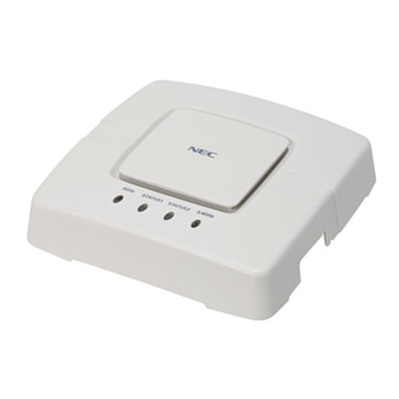
802.11a and two 802.11b/g) high-gain antennas. WL1700-MS controls up to four APs (including the internal AP functionality in itself) in the network. One 10/100 Base-Tx port is provided on the front panel of WL1700-MS. The following is a figure of the WL1700-MS. OVERVIEW... -
Page 39: Wl Access Point
WL Access Point Chapter 1 WL Access Point When associated with a UNIVERGE WL Controllers, the UNIVERGE WL AP provides advanced 802.11a and/or 802.11b/g Access Point functions In the UNIVERGE WL System, most of the processing responsibility is removed from traditional SOHO APs and resides in the UNIVERGE WL Controllers. WL Access Points can receive electrical power from Power over Ethernet (PoE) equipment. -
Page 40: Network Topology With Wl Controllers
WL5100 is capable of connecting 12 APs. SCA-WL10 is capable of connecting up to four APs. WL1700-MS is capable of connecting up to four APs (including an internal AP functionality in itself). When operating with Layer 2 (data link) mode, a WL Controller and the associated WL Access Points must be located in the same segment (subnet). -
Page 41: Data-Processing System
Network Topology with WL Controllers Chapter 1 Data-Processing System As data-processing system between WL Controller and WL Access Points, UNIVERGE WL System can be configured to perform by the following: Centralized Path When Centralized Path is used, all the packets from terminals to Access Points are transferred to WL Controller, and then the WL Controller transmits the packets to those appropriate destinations. -
Page 42: Mobility Domain
Network Topology with WL Controllers Chapter 1 Mobility Domain UNIVERGE WL System can create mobility domains, which contains multiple WL Controllers. Mobility Domain is a special domain for Mobility terminals. When the mobility user roams and connects to another Access Point that the different Controller but assigned to the Mobility Group manages, the user do not need to acquire a new IP address from the Controller again;... - Page 43 Controller in the Mobility Domain. In the case of WL5100 and SCA-WL10, Mobility Domain constitutes a maximum of 32 WL Controllers. In the case of WL1700-MS, Mobility Domain constitutes a maximum of six WL Controllers For example: Using WL5100 or SCA-WL10 as a seed, up to 32 WL Controllers (31 WL Controllers...
-
Page 44: Voice Extension
Chapter 1 function as members) can be accommodated per Mobility Domain. Using WL1700-MS as a seed, up to six WL Controllers (five WL Controllers function as members) can be accommodated per Mobility Domain. However, when using WL1700-MS, Mobility Domain configured with only WL1700-MSs is available. -
Page 45: About Wlms
About WLMS Chapter 1 Note. To perform this function, the Wireless IP terminals must be compatible with voice extension function. About WLMS UNIVERGE WL Management System UNIVERGE WL Management System (WLMS) is network management software that assigns data to WL Controllers and WL Access Points in the network and supervises them. -
Page 46: Specifications
Chapter 1 Specifications Specifications for UNIVERGE WL System are described below: Network Specifications Available* : Available with some restrictions – : Not Applicable Item Details WL5100 SCA-WL10 WL1700-MS Data Centralized Path Available Processing System Radio Resource DCA (Dynamic Channel Available... - Page 47 Specifications Chapter 1 Item Details WL5100 SCA-WL10 WL1700-MS Security Broadcast SSID Disable (Stealth Available Mode) Broadcast SSID ON/OFF per SSID Available Rogue AP Detection Available Rogue AP Containment Available Available* Rogue AP Location Detection Available Available* Rogue AP Location Discovery...
- Page 48 Specifications Chapter 1 Item Details WL5100 SCA-WL10 WL1700-MS Authentication IEEE Available 802.1X TTLS Available (Not supported for Internal RADIUS Server) Available PEAP (Microsoft) Available PEAP (Cisco) Available Available WPA-PSK Available WPA2-PSK Available RADIUS Accounting Server Available Server Authentication Server Available...
- Page 49 Specifications Chapter 1 Item Details WL5100 SCA-WL10 WL1700-MS Virtual Access A maximum of SSIDs Point Multiple Authentication Policy *Per SSID, Available (SSIDs L2/L3 Individual Setting available configuration) Radio Standard IEEE802.11a/b/g Network Policy Configuration Available Security Policy Configuration Available QoS Policy Configuration *Per...
- Page 50 Specifications Chapter 1 Item Details WL5100 SCA-WL10 WL1700-MS IEEE802.11b Voice QoS Downlink QoS Available Extension * It depends on the Function (by terminals Wi-Fi Phone) Bandwidth Call Admission Available Manageme Control Automatic Bandwidth Available Release Bandwidth Available Configuration Sharing Bandwidth...
- Page 51 Specifications Chapter 1 Item Details WL5100 SCA-WL10 WL1700-MS Others Layer3 Tunneling Function Available Available* AP Static-IP Address Configuration Available (L3 Mode) Basic Rate Set (1/2Mbps Disable) Available Tunneling Release by DHCP Available* Discover Site Survey mode Available* Maintenance Network Available...
-
Page 52: Specifications For Wl Controllers
Specifications Chapter 1 Specifications for WL Controllers Category/Function WL5100 SCA-WL10 Wired Interface AP Connection Appliance Mode Available Available Mode Direct Mode Unavailable Unavailable Fixed 10/100Base-TX Physically two ports; – however, only Port 1 is available. 10/100/ Physically two ports; 1000Base-T however, only Port 1 is –... -
Page 53: Specifications For Intelligent Access Points
Specifications Chapter 1 Specifications for Intelligent Access Points Category/Function WL1700-MS AP Connection Mode Appliance Mode Available Direct Mode Unavailable Wired Interface 10/100Base-TX Antenna Built-in (compliance to diversity) Available External Terminals – Physical Layer/MAC Standard. IEEE 802.11a Available IEEE 802.11b Available IEEE 802.11g... -
Page 54: Specifications For Access Points
Specifications Chapter 1 Specifications for Access Points Category/Function WL1500-AP Wired Interface 10/100Base-Tx Antenna Embedded Available (for diversity) External Terminals R-SMA Physical Layer/MAC IEEE802.11a Available IEEE802.11b Available IEEE802.11g Available Modulation Method 5GHz OFDM 2.4GHz OFDM, DSSS Wi-Fi IEEE802.11a Unavailable Available Available IEEE802.11b Available IEEE802.11g... -
Page 55: Specifications For Wlms (Network Management System)
Specifications Chapter 1 Specifications for WLMS (Network Management System) Category/Function WLMS Recommended CPU Intel Pentium 4 – 3.6 GHz or equal 2 GB Recommended Memory Size Microsoft Windows Server 2003 Microsoft Windows XP with Service Pack 1 or higher Microsoft Windows 2000 with Service Pack 4 or higher Number of WL Controllers to be managed by WLMS Number of WL Access Points to be... -
Page 56: Names And Functions Of Each Part Of Wl5100
Names and Functions of Each Part of WL5100 Chapter 1 Names and Functions of Each Part of WL5100 This section describes LEDs, external interface, and external view of WL5100. External View The following is the external views of WL5100. Front View USB Connector Non-use Ether1 Connector... -
Page 57: Led Indication
Names and Functions of Each Part of WL5100 Chapter 1 LED Indication The following explains LEDs of WL5100. Indication Status PWR Lamp Lights green Indicates DC output power is used. Lights off Indicates DC output power is not used. ALM Lamp Lights red Indicates critical alarm Lights off... -
Page 58: Topology
Names and Functions of Each Part of WL5100 Chapter 1 External Interface Remarks Ether1 Connector RJ45 Port is attached on the front. Either 10BASE-T, 100BASE-TX, or 1000BASE-T is available. Ether2 Connector This is for future use. Reset Switch This is attached on the inside of the front cover. This switch is used to reset the WL5100. -
Page 59: Names And Functions Of Each Part Of Sca-Wl10
Names and Functions of Each Part of SCA-WL10 Chapter 1 Names and Functions of Each Part of SCA-WL10 This section describes LEDs, external interface, and external view of SCA-WL10. External View The following is the external view of SCA-WL10. SCA-WL10 is a built-in card, which can be inserted into Multi Purpose Chassis (MPC) module or SV7000 Multi Purpose System (MPS). -
Page 60: Led Indication
Names and Functions of Each Part of SCA-WL10 Chapter 1 Rear View Power Switch AC Power Inlet Cooling FAN PACT Lamp PACT Power Unit Note2 Stopper for AC Power Cable Note1 Note 1: To prevent AC cord from being removed, secure the AC code with the stopper attached on the WL Controller. -
Page 61: External Interface
Names and Functions of Each Part of SCA-WL10 Chapter 1 Note. ALM lamp lights ON when FAN alarm or power failure occurs. Note. LINK lamp lights ON while WL Controller is making connections.When the Controller established a high-speed connection, the blinking lamp might be difficult to see;... -
Page 62: Topology
Names and Functions of Each Part of SCA-WL10 Chapter 1 Topology Topology with SCA-WL10 is as follows: 100M LINK 100M LINK 100M LINK 100M LINK LOAD LOAD Ether1 Ether2 Ether1 Ether2 Connect Ether1 Connector 10BASE-T/100BASE-TX OVERVIEW... -
Page 63: Names And Functions Of Each Part Of Wl1700-Ms
Names and Functions of Each Part of WL1700-MS Chapter 1 Names and Functions of Each Part of WL1700-MS This section describes LEDs, external interface, and external view of WL1700-MS. External View The following is the external views of WL1700-MS. Reset Switch 2.4GHz... - Page 64 Names and Functions of Each Part of WL1700-MS Chapter 1 Back Face View Ether Connector OVERVIEW...
-
Page 65: Leds
Names and Functions of Each Part of WL1700-MS Chapter 1 LEDs The following explains LEDs of WL1700-MS. Indication Status Cont Status Lamp Lights green In normal operation (Indicates status of Lights red - Hardware is in abnormal state (system start-up is incapable). -
Page 66: External Interface
One RJ45 Ports are attached on the back face. Either 10BASE-T or 100BASE-TX is available Reset Switch Used to reboot WL1700-MS. Pressing it for a long time returns WL1700-MS to its factory-set condition. For more information, refer to “In the case of WL1700-MS” on page 174. -
Page 67: Names And Functions Of Each Part Of Access Point
Names and Functions of Each Part of Access Point Chapter 1 Names and Functions of Each Part of Access Point This section describes LEDs, external interface, and external view of WL1500-AP. External View The following is an external view of Access Point. WL1500-AP is a built-in card. 2.4GHz STATUS 5GHz... - Page 68 Names and Functions of Each Part of Access Point Chapter 1 Side View 11B/G 2.4GHz External Antenna Connector 5GHz External Antenna Connector Back Face View Ether1 Connector Ether2 Connector OVERVIEW...
-
Page 69: Leds
Names and Functions of Each Part of Access Point Chapter 1 LEDs The following explains LEDs of WL1500-AP. Indication Status Status Lamp Lights green Indicates normal operation in the following: - Access Point has booted normally - Access Point is making connection with a WL Controller - One of radios is valid, or multiple radios are invalid but the scanning is active (sentry mode). -
Page 70: External Interface
Names and Functions of Each Part of Access Point Chapter 1 External Interface The following explains the external interface. External Interface Remarks Ether1 Connector Two RJ45 Ports are attached on the back face. Either 10BASE-T or 100BASE-TX is available Ether2 Connector 5GHz External Antenna R-SMA connector for 5GHz (802.11a) external antenna Connector... -
Page 71: Check Packages
BEFORE INSTALLATION This chapter explains important instructions before starting to install equipment. Check Packages Check to see whether all of the items are included in the package. For more information, refer to “Confirm Contents of The Package” on page xxiii. Check Mounting Locations Location for WL Controller WL Controller can be placed anywhere, however, in the terms of safety and... - Page 72 Check Mounting Locations Chapter 2 Make sure that length of cables (10Base-T/100Base-TX/1000Base-T) between WL Controller and equipment is less than 100 meters/328`1ft. When mounting WL Controller into a rack, you need to check the following: When mounting a single WL Controller into a rack, put it in the lowest level.
-
Page 73: Location For Wl Access Point
Check Mounting Locations Chapter 2 Note. Connect the Controller’s electric cable to the AC inlet (AC100–240V) with ground connection. Location for WL Access Point Since suitable locations for APs and the required number of APs vary depending on the environment of the site, to provide the overall coverage, you need to perform site survey to figure out how many Access Points are necessary and where they are supposed to be located. -
Page 74: Installation Procedures
Installation Procedures Chapter 2 Installation Procedures WL5100/SCA-WL10 The following are installation procedures in the case of WL5100 and SCA-WL10. START For WL5100 For SCA-WL10 Insert it to Insert SCA-WL10 into the expansion slot of SV7000 MPS / SV7000MS/MPC module (page Mount it into 19-inch rack Mounting the WL Controller into 19-inch rack (page... -
Page 75: Wl1700-Ms
Installation Procedures Chapter 2 WL1700-MS The following are installation procedures in the case of WL1700-MS. Start Assign data for the WL1700-MS and Access Points – When using Command Line Interface (page Data Settings for WL1700-MS – When using WebView (page 109) –... - Page 76 Installation Procedures Chapter 2 BEFORE INSTALLATION...
-
Page 77: Mounting
INSTALLATION This chapter explains the mounting procedures and cable connection. Mounting WL5100 Mounting WL5100 can be mounted into 19-inch rack. For more information, refer to “Mounting Into 19-Inch Rack” on page SCA-WL10 Inserting SCA-WL10 is inserted into the expansion slot of SV7000 MPS/MPC, then mounted into 19-inch rack. -
Page 78: Mounting Into 19-Inch Rack
Mounting Chapter 3 Screw the right and left sides of SCA-WL10 to fix it. Phillips driver Note. For more information about mounting into 19-inch rack, refer to “Mounting Into 19-Inch Rack” on page Mounting Into 19-Inch Rack The following explains the procedures for mounting into 19-inch rack. Ask several installers to do this task for safety purposes. - Page 79 Mounting Chapter 3 Screwing the rack mounting brackets to the sides (When recommended rack is used) M5 screw M4 screw M5 screw M4 screw Bracket-B M4 screw Bracket-A (407 433 mm) M4 screw Bracket-B M4 screw M4 screw M4 screw Bracket-A * When WL Controllers are shipped, rack mount brackets are attached to the Controllers.
- Page 80 Mounting Chapter 3 Screwing the rack mounting brackets to the sides (Using open rack) Rack Mounting Bracket (Attachment on the module) M4 Screw Front (Attachment on the module) Rack Mounting Bracket Attachment on the module Rear M4 Screw Attachment on the module Mount WL Controller into 19-inch rack.
- Page 81 Mounting Chapter 3 The following is an example when WL Controller is mounted in standard EIA19-inch rack. After Mounting 19-inch rack (inch type) In the case of standard JIS 19-inch rack, fix WL Controller with M5 screws. Attachment on 1U BRACKET (E) M5 Screw INSTALLATION...
-
Page 82: Cable Connection
Cable Connection Chapter 3 Cable Connection This section explains how to connect PC/Network Equipment with WL Controller. The following is an example using SCA-WL10. Front View 100M LINK 100M LINK LOAD Ether1 Ether2 Connect to Ether1 Connector 10BASE-T/100BASE-TX (Straight cable) 10BASE-T/100BASE-TX (Cross-over cable) Network Equipment (such as SW HUB) -
Page 83: Power Cable Connection
Cable Connection Chapter 3 Power Cable Connection Insert an AC power cable into AC socket located on the rear side. Before doing this, make sure the power of the Controller is set to OFF. Note. For ground connections, Class A grounding is required for SCA-WL10, and Class D grounding is required for WL5100. - Page 84 Cable Connection Chapter 3 In the case of installing SCA-WL10 Make sure the power is set to OFF. Rear AC power cable INSTALLATION...
- Page 85 Cable Connection Chapter 3 Fasten the AC power cable by tightening the stopper. The following are an example of SCA-WL10. Tightening Stopper to Prevent AC Power Cable from Being Removed Rear Stopper AC power cable *To unplug AC power cable from the Controller, push the hook toward the outside to remove the fix belt, and slide the belt by pushing lug toward the outside.
- Page 86 Cable Connection Chapter 3 Connect the other side of the AC power cable to an AC Power inlet. This is an example when connected to power unit in the lower level. The following is an example of SCA-WL10. Connect the other side of connector into an appropriate inlet AC power cable Power Unit (Example) 19-inch rack (mm type)
-
Page 87: Connecting Pc With Wl Controller
Cable Connection Chapter 3 Connecting PC with WL Controller Use a cross-over cable to connect PC with WL Controller. In the case of WL5100 Connect to Ether1 connector 10BASE-T/100BASE-TX/1000BASE-TX (Cross-over cable) Maintenance Console INSTALLATION... - Page 88 Cable Connection Chapter 3 In the case of SCA-WL10 Connect to Ether1 connector 10BASE-T/100BASE-TX (Cross-over cable) Maintenance Console INSTALLATION...
-
Page 89: Powering On
Cable Connection Chapter 3 Powering On Turn on the power of WL Controller. Turn on the power of AC power source such as Power Unit. This is an example of SCA-WL10 mounted in a 19-inch rack. Power Unit INSTALLATION... - Page 90 Cable Connection Chapter 3 Turn on the power of WL Controller. In the case of WL5100 Loosen the screw on the front cover, and open it. Phillips Driver Turn on the power. ON(UP) Power Switch Put the front cover on and screw it. INSTALLATION...
- Page 91 Cable Connection Chapter 3 In the case of SCA-WL10 Turn on the power. ON(Up) Power Switch Rear View Check to see the PWR lamp lights green on the front cover. INSTALLATION...
-
Page 92: Access Point Installation
For single configuration in WL1500-AP, use ETHER1 connector or ETHER2 connector either. Connecting PC with WL1700-MS When using WL1700-MS, data must be assigned to the WL1700-MS before you attach it to the appropriate position. For more information, refer to “Data Assignment For Intelligent AP (Using Initial Setup)”... -
Page 93: Attaching Aps To Ceiling (Flush Ceiling Tiles)
Note. The following steps are explained using WL1500-AP. In the case of installing WL1700-MS, follow the same steps as explained below. To attach an AP to ceiling, make holes in the appropriate parts of the ceiling by using the mounting template. - Page 94 Access Point Installation Chapter 3 Put a T bar on the surface (with no-letters) of mounting bracket, and fit the mounting bracket to the T bar. Mounting Bracket Port Connecting Hole Mounting Bracket T Bar T Bar Port Connecting Hole Put a LAN cable through the port connecting hole of the mounting bracket, and connect it to WL Access Point.
- Page 95 Access Point Installation Chapter 3 Match the positions of WL Access Point and Mounting bracket, and insert a Phillips driver into the driver slot labelled Unlock. And then push it until a click is heard. Fixed T Bar Note. Please leave 20cm (7.9 inch) or more between AP and external antenna when connecting an external antenna to WL1500-AP.
-
Page 96: Attaching Aps To Ceiling (Drrp Ceiling Tiles)
Note. The following steps are explained using WL1500-AP. In the case of installing WL1700-MS, follow the same steps as explained below. To attach an AP to ceiling, make holes in the appropriate parts of the ceiling by using the mounting template. - Page 97 Access Point Installation Chapter 3 Insert a Phillips driver into the driver slot labelled Unlock, and push it until a click is heard. Remove the mounting brackets from WL Access Point. Put a T bar on the surface (with no letters) of mounting bracket, and fit the mounting bracket to the T-type mounting bracket.
- Page 98 Access Point Installation Chapter 3 Put a LAN cable through the port connecting hole of the mounting bracket, and connect it to WL Access Point. Match the positions of WL Access Point and Mounting bracket, and insert a Phillips driver into the driver slot labelled Lock. And then push it to fix the AP until a click is heard.
-
Page 99: Attaching Aps To Rigid Wall Or Ceiling
Note. The following steps are explained using WL1500-AP. In the case of installing WL1700-MS, follow the same steps as explained below. To attach an AP to ceiling, make holes in the appropriate parts of the ceiling by using the mounting template. - Page 100 Access Point Installation Chapter 3 Position the bracket on wall or ceiling, seeing letters on its surface. If the wall or the ceiling is made from soft material such as gypsum board, position the mounting template at the appropriate part and make holes (5 mm) by using a drill, and then hammer wall anchors to the holes and fix it by screwing them.
- Page 101 Access Point Installation Chapter 3 Match the positions of WL Access Point and mounting bracket, and insert a Phillips driver into the driver slot labelled Lock. And then push it until a click is heard. Make sure the Access Point is locked in the mounting bracket. Cable Mounting Bracket Fixed...
-
Page 102: Tabletop Mounting
Note. The following steps are explained using WL1500-AP. In the case of installing WL1700-MS, follow the same steps as explained below. Insert a Phillips driver into the driver slot labelled Unlock, and push it until a click is heard. Remove the mounting brackets from WL Access Point. - Page 103 Access Point Installation Chapter 3 Turn the bracket over and make sure the letters on its surface. Match the positions of WL Access Point and mounting bracket, and insert a Phillips driver into the driver slot labelled Lock. And then push it to fix the AP until a click is heard.
- Page 104 Access Point Installation Chapter 3 Attach rubber feet to the appropriate parts of WL Access Point. Place WL Access Point on the table correctly. Note. Please leave 20cm (7.9 inch) or more space between AP and external antenna when connecting an external antenna to WL1500-AP. INSTALLATION...
-
Page 105: Connecting To Access Points
Access Point Installation Chapter 3 Connecting to Access Points After WL Controller is mounted and installed, connect the WL Access Points to a network. When UNIVERGE WL System operates with Layer 2 mode, WL Access Point will search for a WL Controller in the network, and send connection demand. In this case, you have to put APs in the same subnet (segment) with the WL Controller. - Page 106 Access Point Installation Chapter 3 INSTALLATION...
-
Page 107: Self Diagnosis
WL Controller by using CLI or WebView. In the case of WL1700-MS After WL1700-MS has started up (CONT STATUS lamp lights green), check to access the WL Controller by using CLI, WebView, or Initial Setup tool. WL Controller routinely checks the connected Access Points in a cycle of one second. -
Page 108: Data Assignment
SCA-WL10 (page 109) In the case of using this setup tool, Internet Explorer 6.0 is required. Initial Setup WL1700-MS Provides easy data setup from an initial state by Web (page 146) Browser. In the case of using this setup tool, Internet Explorer 6.0 is required. -
Page 109: Setup Data Assignment Using Cli
Data Assignment Chapter 4 Setup Data Assignment Using CLI This section describes data assignment for WL Controller and WL Access Points by using Command Line Interface (CLI). Before Doing This Task When you perform data assignment using CLI, the following information are required: IP address and subnet mask for a WL Controller Default Gateway’s IP address and subnet mask... -
Page 110: Text And Syntax Conventions
Chapter 4 The following is an example when connecting a PC to the Ethernet connector on the WL1700-MS. WL1700-MS must be provided electricity from PoE Feeding Adaptor or PoE Hub. Use straight cables to connect to the Ether connector of WL1700-MS. - Page 111 Data Assignment Chapter 4 Table 1. Text and Syntax Conventions Convention Meaning [ ] (square Enclose optional You must enter dynamic or port brackets) parameters in command and a port list in the following syntax. command, but a VLAN ID is optional: { } (curly Enclose mandatory...
-
Page 112: About Cli
Data Assignment Chapter 4 About CLI The two types of the command mode exist in WL Controllers: Network Access Mode and Administrative Access Mode. When you log in to a Controller, you automatically enter Network Access Mode. To configure the Controller settings, type enable to enter Administrative Access Mode. -
Page 113: Error Messages For Command Input
Data Assignment Chapter 4 The CLI provides online help for CLI command. To see the full range of commands available at your access level, type the help command or question mark (?) help WL111111> Command: -------------------------------------------------------------- Clear Clear aaa accounting parameters dir____________________Show list of files on flash device _:____________________________________: WL111111>? -
Page 114: Overview For Basic Data Assignment Using Cli
Data Assignment Chapter 4 Overview for Basic Data Assignment Using CLI The following is an overview for basic data assignment using CLI, which is labelled in “Procedures for Data Assignment Using CLI” on Basic Settings page 83. START Log in to Controller via telnet From step 1 on page 83 Enter Administrative access mode... - Page 115 Data Assignment Chapter 4 PREVIOUS PAGE Create Radio Profiles From step 30 on page 98 Specify RF Setting From step 36 on page 100 Save Configuration File From step 41 on page 103 Restart System From step 42 on page 103 Connect to Network From step 43 on page 104...
- Page 116 Data Assignment Chapter 4 Completing the procedures with can create a WL network with the Basic Settings minimum settings. The following is an example of network configurations when you proceed the basic settings. RADIUS Server DHCP Server IP Address 192.168.10.100 Ch=11 Default Gateway Tx=10...
-
Page 117: Procedures For Data Assignment Using Cli
192.168.100.10 to connect to the WL Controller. C:\Documents and Settings\NEC>telnet 192.168.100.10 The following message appears and asks you to input a user name and a password. At initial setting, user name (nec) and password (nec) are assigned. Type those ones in the prompt. User name:nec Password: Note. - Page 118 If the option (encrypted) is typed after the command, the password will be displayed with plain text. The following is an example when a user name (tom) and a password (nec) is specified in the command.
- Page 119 Data Assignment Chapter 4 Setting of Date Type set timedate date {January| February| March| April | May | June | July | August | September | October | November | December} {1-31 (day)} {1970-2037 (year)} time {00-23 (time)}:{00-59 (minute)}: {00-59 (second)}.
- Page 120 Data Assignment Chapter 4 Country Country Code Country Code Country Code India Switzerland Ireland Taiwan Israel Thailand Italy United Arab Emirates Japan United Kingdom Liechtenstein United States Luxembourg – – Note. Under no circumstances should you specify a country code that does not match the country of operation.
- Page 121 If you want to include a space in the system name, you have to enclose the system name with quotation marks (“ ”). The following is an example when system name (nec) are specified in the command. Check to see the next prompt is changed to characters you just entered.
- Page 122 Data Assignment Chapter 4 Type set ap {ap number} serial-id {AP Serial ID} model {AP Model } radiotype {11b (802.11b) | 11g (802.11b/g)}. At default, 11g (802.11b and 802.11g are available) is selected. If you want to use 802.11b only, set 11b as radio type.
- Page 123 Data Assignment Chapter 4 Create Mobility Domain. Mobility Domain consists of two types of Controllers: seed and member. In a mobility domain, a single seed distributes the mobility domain information to the members, and make a particular domain network across multiple networks.
- Page 124 Data Assignment Chapter 4 Enable/Disable Secure Shell (SSH) service for the purpose of maintenance. Type set ip ssh server {enable | disable} to enable/disable SSH service. This function is enabled at default. The following is an example when SSH service is enabled in the command. WL111111#set ip ssh server enable Enable/Disable Web Interface (WebView) for the purpose of maintenance.
- Page 125 Data Assignment Chapter 4 Type set interface {VLAN ID:1–4093} ip {IP Address} {Subnetmask} to assign IP addresses to Interfaces on the Controller. The following is an example when vlan ID (2), IP address (192.168.20.10), and Subnet mask (255.255.255.0) are specified in the command. WL111111#set interface 192.168.20.10 255.255.255.0 Specify the Remote Authentication Dial In User Service (RADIUS) Server.
- Page 126 Data Assignment Chapter 4 Enable/Disable Web Authentication. Type set web-portal {enable | disable} to enable/disable Web Authentication. This function is enabled at default. The following is an example when Web Authentication is enabled in the command. WL111111#set web-portal enable Enable/Disable Simple DHCP Server function. Type set interface {Interface Number} ip dhcp-server {enable | disable} start {Start IP Address} stop {End IP Address}.
- Page 127 Data Assignment Chapter 4 Assign RF Security. Basic Settings Profile for ESSID (B1) The following is an example when 802.1X is set to Service Profile (Dot1x-B) in ESSID (B1) WL111111#set service-profile Dot1x-B attr vlan-name default Profile for ESSID (B2) The following is an example when WPA (TKIP) is set to Service Profile (WPA-B) in ESSID (B2) WL111111#set service-profile WPA-B...
- Page 128 Data Assignment Chapter 4 Required Data Assignment Security WPA-PSK set service-profile {Service Profile Name} wpa-ie enable (TKIP) set service-profile {Service Profile Name} auth-psk enable set service-profile {Service Profile Name} auth-fallthru last-resort set service-profile {Service Profile Name} psk-phrase {PSK shared key: 8–63characters} set service-profile {Service Profile Name} auth-dot1x disable set service-profile {Service Profile Name} attr vlan-name {VLAN name} WPA2-PSK...
- Page 129 Data Assignment Chapter 4 Combining parameters related to Service Profiles can create a various of Security Modes. Detailed information for each Security Mode are as follows. The detailed information can be displayed by the show service-profile {Profile Name} command. Table 3. Parameters for Security Modes Security Mode...
- Page 130 Data Assignment Chapter 4 Specify Transmitted Speed in Access Point. Type set service-profile {Service Profile Name} transmit-rate {11a (802.11a) | 11b (802.11b) | 11g (802.11g)} mandatory {data transmission rate to be used <Mbps>} disabled {disabled data transmission rate <Mbps>} beacon-rate {beacon rate:1.0 | 2.0 <Mbps>) | Auto} multicast-rate {multicast rate<Mbps>}.
- Page 131 Data Assignment Chapter 4 Specify Voice Session Reserve Time for moving out of RF range (Voice Extension Function). If no respond occurs between a terminal and a Controller, and a certain period of time defined as active-call-idle-timeout elapses, the Controller releases VoIP bandwidth.
- Page 132 Data Assignment Chapter 4 number of sessions per ESSID:0 100}. – The following is an example when the available number of sessions (10) per ESSID is assigned to Service Profile (Dot1x-B) in the command. WL111111#set service-profile Dot1x-B cac-session Enable/Disable Proxy ARP (Voice Extension Function). Using this function make it available to respond to the ARP request from terminals located in different segments.
- Page 133 Data Assignment Chapter 4 Enable/Disable Automatic Channel Assignment function of Access Points. Basic Settings UNIVERGE WL manages items available on a Radio Frequency (RF) basis by using a profiles called Radio Profile. Enable/Disable the Automatic Channel Assignment function, which can enable/disable all the channels assigned to a Radio Profile.
- Page 134 Data Assignment Chapter 4 Specify QoS settings (Voice Extension Function). This Quality of Service (QoS) function is to distinguish Layer 3 from Layer 2, to track marking, to set transferring queue of APs. Type set radio-profile {Radio Profile Name} qos-mode {svp (SpectraLink Voice Priority) | wmm (Wi-Fi Multi-Media) | voice-extension (Voice Extension Function)} to specify QoS.
- Page 135 Data Assignment Chapter 4 To customize auto-tuning power configurations, type set ap {AP Number} radio {RF Number:1-2} channel {channel number}. The following is an example when a channel (6) is specified in AP Number (1)’s RF Number (1), a channel (36) is specified in AP Number (1)’s RF Number (2), and a channel (11) is specified in AP Number (2)'s RF Number (1).
- Page 136 Data Assignment Chapter 4 The relationships between Service Profiles and Radio Profiles, Radio Profiles and RF Modules are as follows: Map two types of RF modules (IEEE802.11a and IEEE802.11b/ g) to an AP. Map Service Profiles (up to 32 profiles) to step 39 a Radio Profile RF Module (802.11a/b/g)
- Page 137 Data Assignment Chapter 4 Enable AP’s RF modules. Basic Settings Type set ap {AP Number} radio {RF Number:1 2} mode enable. The – following is an example when AP Number (1)’s RF Numbers (1 and 2) and AP Number (2)’s RF Number (1) are enabled. WL111111#set ap radio mode enable...
- Page 138 Connect the LAN cable to Ether1 Connector. 10BASE-T/100BASE-TX LAN/WAN Network Equipment (SW HUB,etc) Maintenance Console The following is an example when connecting WL1700-MS to LAN/WAN. Connect the LAN cable to Ether connector of WL1700-MS. Rear Connect a LAN cable to the Ether Connector. 10BASE-T/100BASE-TX...
- Page 139 “Check Configurations/Network Status” on page 106. When WL1700-MS is used, after confirming that the Controller is in normal state, attach the WL Intelligence Access Point to an appropriate location. For more information, refer to “Access Point Installation” on page...
-
Page 140: Check Configurations/Network Status
Data Assignment Chapter 4 Check Configurations/Network Status Use the following show commands to check the status of Controllers and APs. For more information about other commands, refer to the Command Guide. <Setting Readout Command> To show current configurations To show only difference data from default settings WL111111# show configuration To show all the data WL111111# show configuration all... - Page 141 Data Assignment Chapter 4 <Status Readout Command> To show terminals associated with a Controller WL111111# show sessions network User Sess IP or MAC VLAN Port/ Name Address Name Radio ------------------------- ----- ------------- ------- ----- last-resort-EB-Evaluation 192.168.10.113 default AP2/1 *2*3 1 sessions total *1: VLAN name that the terminal belongs to.
- Page 142 Data Assignment Chapter 4 test# show arp ARP aging time: 1200 seconds Host HW Address VLAN State Type ------------------ ---------------- --------- ------- 192.168.10.114 00:10:ec:80:9b:ba RESOLVED DYNAMIC 192.168.10.113 00:02:c7:bc:a3:92 RESOLVED DYNAMIC 192.168.10.127 00:02:c7:9a:d7:c4 RESOLVED DYNAMIC 192.168.10.150 00:0b:0e:31:08:7c RESOLVED DYNAMIC To show status of Ports WL111111# show port status Port Name Admin Oper Config Actual...
-
Page 143: Setup Data Assignment Using Webview
Data Assignment Chapter 4 Setup Data Assignment Using WebView This section describes data assignment for WL Controller and WL Access Points by using WebView. Before Doing This Task When you perform data assignment using WebView, PC and Controller must be connected directly. - Page 144 Chapter 4 The following is an example when connecting a PC to the Ethernet connector on the WL1700-MS. WL1700-MS must be provided electricity from PoE Feeding Adaptor or PoE Hub. Use straight cables to connect to the Ether connector. Rear...
- Page 145 Chapter 4 WebView is open, and the following dialog appears. Log in to the controller by entering the user name (nec) and password (nec). The following dialog appears. User name and password are not set at initial setting, just leave blank and click the OK button.
-
Page 146: About Webview
Data Assignment Chapter 4 About WebView This section describes an overview of WebView functions. WebView has the left menu and the top right menu. The left menu (main menu) are in the following: [Monitoring]: Network Equipment Supervision [WLANs]: Logical Settings for Wireless LAN [Controller]: Settings for WL Controllers (VLANs and Ports) [Wireless]: Settings for WL Access Points (Field Intensity and Channels) [Security]: Settings for Security (RADIUS Servers and MAC filters) - Page 147 Data Assignment Chapter 4 The top right menu are in the following: [Refresh] : Refreshes the current screen. [Save Configuration]: Saves the configuration. [Ping] : Performs ping to a specified device. [Logout] : Terminates WebView. INITIAL SETUP...
-
Page 148: Overview For Basic Data Assignment Using Webview
Data Assignment Chapter 4 Overview for Basic Data Assignment Using WebView The following is an overview for data assignment using WebView, which is labelled in “Procedures for Data Assignment Using WebView” on Basic Settings page 118. START Specify a System Name Controller From step 1 on page 118... - Page 149 Data Assignment Chapter 4 PREVIOUS PAGE Assign Data to RF of Access Point From step 15 on page 136 Use Authentication? (802.1X, WPA,etc) Security Setting Controller From step 16 on page 138 Save the Configuration From step 19 on page 142 Restart the System From step 20 on page 143...
- Page 150 Data Assignment Chapter 4 Performing the following steps with marks (minimum settings) can Basic Settings create a WL network. The following is a network configuration when you perform the basic settings. RADIUS Server DHCP Server IP Address 192.168.10.100 Ch=11 Default Gateway Tx=10 ESSID=B1(802.11x) IP Address 192.168.10.25...
-
Page 151: Text And Syntax Conventions
Data Assignment Chapter 4 Text and Syntax Conventions The following Text and Syntax Conventions are used in this guide. Table 4. Text and Syntax Conventions Convention Meaning Indicates necessary steps to create a WL network. Basic Settings [Basic Setting] Indicates a parameter required for creating WLAN network. -
Page 152: Procedures For Data Assignment Using Webview
Data Assignment Chapter 4 Procedures for Data Assignment Using WebView Specify a system name. Basic Settings Select [Controller] - [System] on the main menu, and specify the following: ITEMS REMARKS System Name of WL Controller System Name [Basic Setting : system1] Note. - Page 153 Data Assignment Chapter 4 Assign the current date and time to WL Controller. Basic Settings Select [Controller] - [Set Time] on the main menu, and specify the information and then click the Apply button. Timezone: Specify appropriate timezone. ITEMS REMARKS Timezone To specify a timezone, select Enable.
- Page 154 Data Assignment Chapter 4 INITIAL SETUP...
- Page 155 Data Assignment Chapter 4 Assign an IP address to each interface. Basic Settings Select [Controller] - [Interfaces] on the main menu. Click the Edit button to display the Edit Interface screen, which can edit interface settings on the vlan (default). Specify the following items and click the Apply button.
- Page 156 Data Assignment Chapter 4 Assign VLANs. Select [Controller] - [Interfaces] on the main menu. Select a vlan from VLAN Table, and click the Edit button to display the Edit VLAN screen. Specify the following items and click the Add button. ITEMS REMARKS Port...
- Page 157 Data Assignment Chapter 4 Specify a system IP address for WL Controller. Basic Settings Select [Controller] - [System] on the main menu. Specify the following and click the Apply button. ITEMS REMARKS System IP Address Assign a system IP address for WL Controller. [Basic Setting: 192.168.10.10] Changing the system IP address of WL Controller will cause all the related APs to reset.
- Page 158 Data Assignment Chapter 4 Specify the default route information. Basic Settings Select [Controller] - [Interfaces] on the main menu. Click the New button in Router Table to display New IP Route screen. Specify the following and click the Add button. ITEMS REMARKS Destination...
- Page 159 Data Assignment Chapter 4 Create Mobility Domain. Select [Controller] - [Mobility Domains] on the main menu. Click the Edit Group button to display the Edit Mobility Domain screen. Specify the following and click the Apply button. These may be set when the State/Mode is in Seed. ITEMS REMARKS Mobility Domain Name...
- Page 160 Data Assignment Chapter 4 Enable/Disable telnet and SSH services for the purpose of WL Controller management. Select [Management] - [Telnet/SSH] on the main menu. Specify the following and click the Apply button. ITEMS REMARKS Allow New Telnet Sessions Enable/Disable telnet service. This function is enabled at default.
- Page 161 Data Assignment Chapter 4 Enable/Disable SNMP services for the purpose of WL Controller management. Select [Management] - [SNMP General] on the main menu. Specify the following and click the Apply button. This service must be enabled if you will use UNIVERGE WL Management System (WLMS). ITEMS REMARKS SNMP Service...
- Page 162 Data Assignment Chapter 4 Assign VLANs. Select [Controller] - [Interfaces] on the main menu. Click the New button to display the New VLAN screen. Specify the following and click the Add button. ITEMS REMARKS VLAN-ID Specify a VLAN ID. VLAN Name Specify a VLAN name.
- Page 163 Data Assignment Chapter 4 Create Interfaces. Select [Controller] - [Interfaces] on the main menu. Click the New button to display the New Interface screen. Specify the following and click the Add button. ITEMS REMARKS VLAN-ID Select a VLAN ID from the list. Admin Status Select Enabled.
- Page 164 Data Assignment Chapter 4 Create Service Profiles. Basic Settings In UNIVERGE WL system, a set of data assignment for Security (Security Policy), which can be specified per ESSID, is managed as a Service Profile. To create the Service Profile, select [WLANs] - [Service Profiles] on the main menu.
- Page 165 Data Assignment Chapter 4 ITEMS REMARKS Authentication Method Assign Authentication Method (available when WPA or WPA2 is selected in the Security Type). - 802.1X - PSK PSK Passphrase Assign a Phase Shift Keying (PSK) value as option (available when WPA or WPA2 is selected in the Security Type).
- Page 166 Data Assignment Chapter 4 INITIAL SETUP...
- Page 167 Data Assignment Chapter 4 Create Radio Profiles. Basic Settings In UNIVERGE WL System, a set of Radio Frequency, which can be specified per RF module, is managed as a Radio Profile. To create the Radio Profile, select [WLANs] - [Radio Profiles] on the main menu.
- Page 168 Data Assignment Chapter 4 INITIAL SETUP...
- Page 169 Data Assignment Chapter 4 Assign data to Access Points. Basic Settings Select [Wireless] - [Access Points] on the main menu. Click the New AP button to display the New AP screen. Specify the following and click the Add button. ITEMS REMARKS AP No Specify the Access Point Number.
- Page 170 Data Assignment Chapter 4 Assign data to RF of Access Point. Basic Settings Select [Wireless] - [Access Point Radios] on the main menu. Click the Edit button to display Edit AP Radio screen. Specify the following and click the Apply button. [Basic Setting 1: AP802.11b/g Radios AP No=1] [Basic Setting 2: AP802.11a Radio AP No=1] [Basic Setting 3: AP802.11b/g Radios AP No=2]...
- Page 171 Data Assignment Chapter 4 INITIAL SETUP...
- Page 172 Data Assignment Chapter 4 Specify the Remote Authentication Dial In User Service (RADIUS) Server. Basic Settings Select [Security] - [Authentication] on the main menu. Click the New button to display the New RADIUS Server screen. Specify the following and click the Add button.
- Page 173 Data Assignment Chapter 4 Assign RADIUS Server Group. Basic Settings Select [Security] - [Authentication] on the main menu. Click the New button on the RADIUS Server Groups to display the New RADIUS Server Group screen. Specify the following and click the Add button. ITEMS REMARKS Group Name...
- Page 174 Data Assignment Chapter 4 Assign AAA. Basic Settings Select [Security] - [AAA] on the main menu. Click the New button to display New AAA screen. Specify the following and click the Add button. ITEMS REMARKS Auth or Account Select Authentication. [Basic Setting 1/2/3: Authentication] Command Select the Dot1X.
- Page 175 Data Assignment Chapter 4 INITIAL SETUP...
- Page 176 Data Assignment Chapter 4 Save the configuration. Basic Settings Select [Commands] - [Save Configuration] on the main menu. Or select [Save Configuration] on the top right menu. Click the Save Configuration button to save the configuration. INITIAL SETUP...
- Page 177 Data Assignment Chapter 4 Restart the system. Basic Settings This will restart the WL Controller. Select [Commands] - [Save Configuration] on the main menu. Click the Reset button to restart the WL Controller. Confirmation screen is displayed. Click the Save and Reset button to save the configurations. When WL Controller restarts, it reads the new configuration.
- Page 178 Data Assignment Chapter 4 After restart has been completed, connect the Controller to your network (LAN/WAN). The following is an example when PC is connected to SCA-WL10. In the case of WL5100, WL5100 is also connected through Ether 1 connector. Front 100M LINK 100M LINK LOAD...
- Page 179 Data Assignment Chapter 4 The following is an example when connecting WL1700-MS to LAN/WAN. Connect the LAN cable to Ether connector of WL1700-MS. Rear Connect a LAN cable to the Ether Connector. 10BASE-T/100BASE-TX PoE HUB PoE Feeding Adaptor/ PoE HUB Setup PC Check to see if the Controller is operating normally in your network.
-
Page 180: Data Assignment For Intelligent Ap (Using Initial Setup)
Initial Setup tool. Note. This tool can be used on condition that WL1700-MS is in an initial state. If data setting on the WL1700-MS have been changed from the initial state, it is required to return to the factory-set condition before data assignment. For more information about how to return to factory-set condition, refer to “Return to factory-set condition”... -
Page 181: Before Doing This Task
WL1500-AP WL1500-AP RF settings of WL1500-APs are the same with those of WL1700-MS. Before Doing This Task When you perform data assignment using Initial Setup tool, PC and Intelligent Access Point must be connected directly. The following are network settings at initial state. - Page 182 Chapter 4 The following is an example when connecting a PC to the Ethernet connector on the WL1700-MS. WL1700-MS must be provided electricity from PoE Feeding Adaptor or PoE Hub. Use straight cables to connect to Ether connector of WL1700-MS.
-
Page 183: Procedures For Data Assignment Using Initial Setup
Data Assignment Chapter 4 Procedures for Data Assignment Using Initial Setup Connecting to WL1700-MS, the following screen is displayed. Perform the following data assignment: INITIAL SETUP... - Page 184 Admin User Name Specify an account name for administrative privilege[A maximum of 31 alphanumeric characters, no space]. By default, nec is assigned. Admin Password Specify a password for the above [A maximum of 38 alphanumeric characters, no space]. By default, nec is assigned.
- Page 185 When you specify a range of IP addresses by “Start IP Address” and “Stop IP Address” (including an IP address for WL1700-MS), avoid overlapping IP addresses already used in a network. Note. Same IP address of WL1700-MS must not be assigned for Internal AP of WL1700-MS as well. INITIAL SETUP...
- Page 186 WL Controller by tunnelling through mobility domain. Thereby, the terminal will be able to move from a network to another network, maintaining sessions and the same IP address on the same VLAN ID. Note. When using WL1700-MS, Mobility Domain configured with only WL1700-MSs is available. INITIAL SETUP...
- Page 187 Data Assignment Chapter 4 Table 6. Configure Mobility Domain, when multiple controllers (such as WL1700-MS) are used. PARAMETERS REMARKS This controller will act as Assign a role (seed or member) to a Controller. By default, None is assigned. – None: Assigned when mobility domain is not created.
- Page 188 Data Assignment Chapter 4 Configure WLAN Network INITIAL SETUP...
- Page 189 Data Assignment Chapter 4 Table 7. Configure WLAN Network PARAMETERS REMARKS Network Name (ESSID) Assign an Extended Service Set Identifier (ESSID) to 802.11b/g and 802.11a each. ESSID is a network identifier of Wireless LAN [A maximum of 32 alphanumeric characters, no space].
- Page 190 Data Assignment Chapter 4 Table 7. Configure WLAN Network PARAMETERS REMARKS WEP-Key/Psk-Phrase Type characters for WEP-Key or Psk-Phrase. This parameter becomes available to input when one of the following is selected in Security: – WPA-PSK(TKIP) – WPA2-PSK(TKIP) – WPA2-PSK(AES/CCMP) – Static-WEP When Static-WEP is selected (WEP-Key): When using alphanumeric...
- Page 191 Data Assignment Chapter 4 Table 7. Configure WLAN Network PARAMETERS REMARKS Server Specify an external Remote Hostname Authentication Dial In User Service (RADIUS) Server name [A maximum of 32 alphanumeric characters, no space]. If no character is assigned, default will be applied.
- Page 192 Intelligent Access Point [10 alphanumeric characters]. Model Select a model to be used. In the case of using APs in Japan, select WL1700-MS(AP)-JP. In the case of other than Japan, select WL1700-MS(AP). External AP1 to AP3 Select this box and specify the...
- Page 193 Data Assignment Chapter 4 Click the Apply button to apply the settings to the AP When no error occur: “Success! You have completed configuration of this device” is displayed. Click the OK button to apply the setting to the system. Then, the configuration data is automatically saved and the system will be restarted.
- Page 194 Data Assignment Chapter 4 INITIAL SETUP...
-
Page 195: Cleaning The Site
AFTER INITIAL SETUP This chapter describes the procedure for cleaning sites. Cleaning The Site When the tasks described in Chapter 2 and Chapter 3 are completed, execute or confirm the following items. Clean inside of the frame, specially around ventilation, FAN, and the bottom of the frame. - Page 196 Cleaning The Site Chapter 5 AFTER INITIAL SETUP...
-
Page 197: Configuration Management
SYSTEM MAINTENANCE This chapter describes the procedure for copying (backup) the data assigned in WL Controller, restoring the backup data, and Power Unit replacement. CLI descriptions in this chapter follows “Text and Syntax Conventions” on page Configuration Management This section describes the procedures for copying (backup) configurations. TFTP Running-Config Flash Card... -
Page 198: Copy
Configuration Management Chapter 6 Copy Use the Copy command to perform the following: Back up data to TFTP Server Restore data from TFTP Server Duplicate data in Flash Card In normal state, WL Controller is activated in the following way. configuration When system restarts,it reads configuration data saved in flash card (default: configuration). - Page 199 Configuration Management Chapter 6 Example 1) When copying the configuration file (file name: configuration) into TFTP Server (192.168.0.1). WL111111#copy configuration tftp://192.168.0.1/configuration Note. The procedures for backup can take the same result. For more information, refer to “Backup” on page 168. Copy configuration stored in flash card into TFTP Server.
- Page 200 Configuration Management Chapter 6 Example 2) Restore data (file name: newconfig) to WL Controller from TFTP Server (192.168.0.1) WL111111#copy tftp://192.168.0.1/newconfig newconfig WL111111#set boot configuration-file newconfig Copy a configuration file stored in TFTP Server into the flash card. It cannot be overwritten to the configuration file stored in the flash card . configuration TFTP Running-Config...
- Page 201 Configuration Management Chapter 6 Configuration files are indicated after “file:”. Software image is indicated after “Boot:” and log file or others are indicated after “temporary files:”. Besides, when subdirectories exists under “file:” area, use dir [directory name] to list the subdirectories. (To display subdirectory “old”, type dir old.) Besides, select an appropriate one of the configuration files saved in the Flash Card.
-
Page 202: Backup
Configuration Management Chapter 6 Backup While you are configuring data, the data is being written into running-config data on memory. Data in the running-config will be lost if the system restarts or is powered off. To retain the configuration after those events, save the data into a Flash Card or TFTP Server. -
Page 203: Backup Into Tftp Server
Configuration Management Chapter 6 Using WebView Select [Monitoring] - [Summary] to display information on the Booted Configuration area. Backup into TFTP Server WL Controller can copy the configuration file into TFTP Server by using TFTP Client function. To back up the configuration file into TFTP Server, use the following: Using CLI Use backup system {TFTP Sever address and file name}. -
Page 204: Delete Configuration Files
Configuration Management Chapter 6 Restore backup configuration file saved in TFTP Server To restore configuration file saved in TFTP Server, type the following command. Using CLI Use restore system {TFTP Sever address and file name}. For example, save it as System-backup in TFTP Server (192.168.0.1). WL111111# restore system tftp://192.168.0.1/System-backup... -
Page 205: Return To Factory-Set Condition
Configuration Management Chapter 6 Return to factory-set condition This section describes the procedures for returning to its factory-set condition. This task can be performed by using CLI, WebView, or Switch on WL Controller. Using CLI Apply factory setting to the configuration file running on the system. Type clear boot config to apply the factory setting. -
Page 206: Using Webview
Configuration Management Chapter 6 Using WebView Select [Command] - [Reset to Factory Default]. Click the Reset to Factory Default button and click the OK button. WL Controller will be set to factory default settings at restart. Log in to the WL Controller by using the factory settings. -
Page 207: Using Switch
Configuration Management Chapter 6 Using Switch In the case of WL5100/SCA-WL10 The following explains procedures for returning WL5100 and SCA-WL10 to factory-set condition. Turn OFF the power of WL Controller, and flip down all the four switches (ON) of the DIP Switch. In the case of SCA-WL10 DIP Switch U S B... - Page 208 In the case of WL1700-MS The following explains procedures for returning WL1700-MS to factory-set condition. Insert an elongated slender rod object into the reset switch of WL1700-MS. Reset Switch Keep pressing the reset switch for 15 seconds, using the rod.
-
Page 209: Power Unit Replacement
Power Unit Replacement Chapter 6 Power Unit Replacement This section describes the procedures for replacing power unit in the WL Controller. Power Unit Replacement for WL5100 Power unit mounted in WL5100 is to be replaceable with one provided as an option. - Page 210 Power Unit Replacement Chapter 6 Loosen the screw on the front cover, and open it. Phillips Driver Turn off the power. DESCRIPTION ISSUE PZ-PW137 Ether 1 LOAD 1 2 3 4 Ether 2 PCCARD RESET LINK/ACT SPEED SYSTEM MAINTENANCE...
- Page 211 Power Unit Replacement Chapter 6 Loosen the screw on the power unit, and pull it. DESCRIPTION ISSUE PZ-PW137 Ether 1 LOAD 1 2 3 4 Ether 2 PCCARD RESET SPEED LINK/ACT SYSTEM MAINTENANCE...
- Page 212 Power Unit Replacement Chapter 6 Insert a new power unit into the slot, and screw it. ISSUE DESCRIPTION PZ-PW137 Ether 1 Ether 2 RESET LINK/ACT SPEED Note. If you will operate it with dual power units (redundant system), insert a power unit into the other side.
- Page 213 Power Unit Replacement Chapter 6 Attach the front cover and screw it. Phillips Driver <Test after replacement> Check to see ACT lamp lights green, and make sure if you are able to access the Controller via CLI or WebView. Power unit replacement is completed. SYSTEM MAINTENANCE...
-
Page 214: Power Unit Replacement For Sca-Wl10
Power Unit Replacement Chapter 6 Power Unit Replacement for SCA-WL10 Power unit of SCA-WL10 mounted in the SV7000 MPS is to be replaceable. The following describes the procedures for replacing the faulty power unit with a new one. Turn off the power. PACT Remove the screws. - Page 215 Power Unit Replacement Chapter 6 Insert a new power unit into the slot, and screw it. P A C T Turn on the power. PACT <Test after replacement> Check to see the replaced power unit is properly working and the ACT lamp lights green, and make sure if you are able to access the Controller via CLI or WebView.
- Page 216 Power Unit Replacement Chapter 6 SYSTEM MAINTENANCE...
-
Page 217: Examples Of System Configurations
APPENDIX This chapter describes examples according to the purpose of functions to be used. Examples of System Configurations The following are examples explained in this chapter. Pattern 1: System Configurations for VLANs (Centralized Path) Pattern 2: System Configuration for Mobility Group Pattern 3: System Configuration for Voice Extension If you want to create a WL network using other functions, refer to the Configurations Guide or the Command Reference. -
Page 218: Pattern 1: System Configurations For Vlans (Centralized Path)
Examples of System Configurations Appendix A Pattern 1: System Configurations for VLANs (Centralized Path) The following is an example using VLANs. This operates in Centralized Path. Key=pon Registered User= VoIP-Group VLAN20 Pass:voip Data-Group VLAN30 Pass:data EAP-Pase2 EAP-Pase2 RADIUS Server SIP Server ID=VoIP-Group ID=Data-Group Pass=voip... - Page 219 Examples of System Configurations Appendix A Table 1. Data Assignment Using CLI Controller 1 CLI Settings Reference System Config Country Code set system countrycode step 6 on page 85 step 8 on System IP set system ip-address 192.168.10.10 page 86 step 9 on Default Gateway set ip route default...
- Page 220 Examples of System Configurations Appendix A Table 2. Data Assignment Using WebView Controller 1 WebView Settings Reference System Config Country Code To specify the country code, refer to CLI. WebView does not step 6 on support to change this information. page 85 step 5 on System IP...
- Page 221 Examples of System Configurations Appendix A Controller 1 WebView Settings Reference Service Profile Config ESS=B1 Profile [WLANs]-[Service Profiles]-[New Service Profile] screen step 12 on -[Profile Name] (Dot1x-B) page 130 -[SSID Name] (B1) ESS=A1 Profile [WLANs]-[Service Profiles]-[New Service Profile] screen -[Profile Name] (Dot1x-A) -[SSID Name] (A1) Radio Profile Config RF1 Profile of AP1...
-
Page 222: Pattern 2: System Configuration For Mobility Group
Examples of System Configurations Appendix A Pattern 2: System Configuration for Mobility Group The following is an example using Mobility Group. ROUTER xxxx HUB xxxxxx HUB xxxxxx Data Assignment Using CLI Controller 1 CLI Settings Reference step 13 on System Config Mobility Config set mobility-domain mode seed... - Page 223 Assign IP address of all members for seed. For each member, assign IP address of seed. Note. In the case of WL5100 and SCA-WL10, a maximum of 31 members can be added per Mobility Domain. In the case of WL1700-MS, a maximum of five members can be added per Mobility Domain. APPENDIX...
-
Page 224: Pattern 3: System Configuration For Voice Extension
Examples of System Configurations Appendix A Pattern 3: System Configuration for Voice Extension The following is an example using Voice Extension function. Codec=G.711 RTP Transmission Cycle=40msec ESSID=VoIP(802.1X) ESSID=VoIP(802.1X) RADIUS Server SIP Server RF1(802.11b) Default Gateway SW-HUB Voice Extension: Enabled (PoE) Active Call TImeout in Out of Area: 120sec ROUTER xxxx HUB xxxxxx... - Page 225 UNIVERGE WL Installation Guide (V1) NWA-027515-001 May, 2007 ISSUE 1.0 Publishing Office Infrontia Corporation Data Wireless Networks Division 2007 NEC Infrontia Corporation Notice All right reserved. The contents of this manual is subject to change without notice. Printed in Japan 0705-010...
Need help?
Do you have a question about the WL1700-MS and is the answer not in the manual?
Questions and answers