Icom IC-FR5100 Instruction Manual
Vhf/uhf dpmr repeater
Hide thumbs
Also See for IC-FR5100:
- Service manual addendum (181 pages) ,
- Service manual (44 pages) ,
- Instruction manual (16 pages)
Table of Contents
Advertisement
Quick Links
Download this manual
See also:
Service Manual
Advertisement
Table of Contents

Subscribe to Our Youtube Channel
Related Manuals for Icom IC-FR5100


Summary of Contents for Icom IC-FR5100
- Page 1 INSTRUCTION MANUAL VHF dPMR REPEATER iFR5100 iFR5100H UHF dPMR REPEATER iFR6100 iFR6100H...
-
Page 2: Important
Thank you for purchasing this Icom repeater. The IC- Handles For handle attachment FR5100/H and the IC-FR6100/H are designed and built with Icom’s state of the art technology and crafts- Spacers Screws manship. With proper care, this product should provide you with years of trouble-free operation. -
Page 3: Table Of Contents
■ Troubleshooting ..........9 ■ Fuse replacement ..........9 D Line fuse replacement ........9 Icom, Icom Inc. and the Icom logo are registered trademarks 5 OPTIONS ............10 of Icom Incorporated (Japan) in Japan, the United States, 6 ABOUT CE ........... 11–12 the United Kingdom, Germany, France, Spain, Russia and/or other countries. -
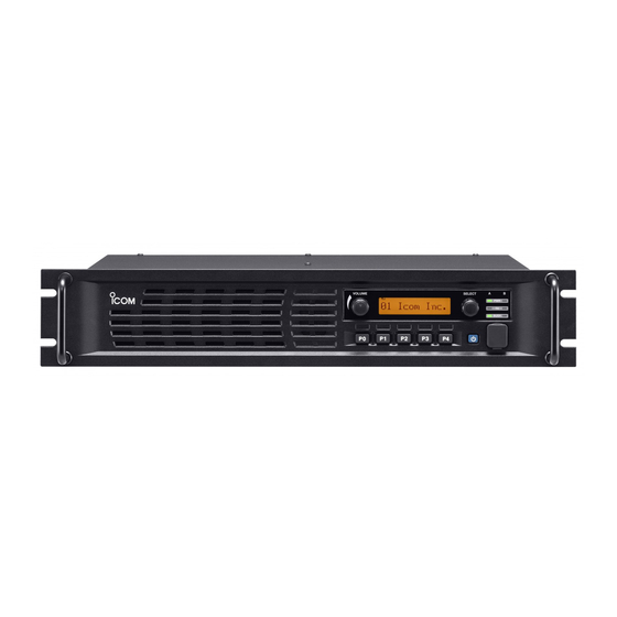
Page 4: Panel Description
ON. When a channel extension module is installed i POWER SWITCH [POWER] (For IC-FR5100/IC-FR6100): ➥ Push to turn ON the repeater power. ➥ Lights green on the selected module indicator, ➥ Hold down for 3 seconds to turn OFF the re- ‘A’... -
Page 5: D Function Display
Shows a variety of text and code information. ■ Rear panel Repeater unit* PA unit * For the IC-FR5100/IC-FR6100, the repeater unit is installed in the right side (back view). q EXTERNAL SPEAKER JACK [SP] y TRANSMIT ANTENNA CONNECTOR [TX] (For IC-FR5100/IC-FR6100) Connects to the optional external speaker. -
Page 6: D Accessory Connector
PANEL DESCRIPTION ■ Rear panel (Continued) D Accessory connector Pin No. Pin Name Description Specification No connection — Output terminal for serial communication data. — Input terminal for serial communication data. — Output terminal for request-to-send data. — Input terminal for clear-to-send data. —... -
Page 7: D I/O Connector (For The Pa Unit)
PANEL DESCRIPTION The list shows the default functions that are assigned to the pins 10, 12, 15, 16, 17, 18, 19, 21, 23, 24 and 25. Default Pin No. Pin Name IC-FR5100/IC-FR6100 IC-FR5100H/IC-FR6100H EXT. D/A Null Null Null UR-PA5000 Temperature Input* EXT. -
Page 8: Installation And Connections
INSTALLATION AND CONNECTIONS ■ Unpacking ■ Grounding After unpacking, immediately report any damage to To prevent electrical shock, television interference the delivering carrier or your dealer. Keep the shipping (TVI), broadcast interference (BCI) and other problems, cartons. ground the transceiver using the GROUND terminal on the rear panel. -
Page 9: Front Panel Connection
CAUTION: DO NOT short pin 1 to ground as this can damage the internal 8 V regulator. DC voltage is applied to pin 1 for microphone operation. Only Icom micro- phones are recommended. ■ Rear panel connection— For the IC-FR5100H/IC-FR6100H... -
Page 10: Rear Panel Connection-For The Ic-Fr5100/Ic-Fr6100
INSTALLATION AND CONNECTIONS ■ Rear panel connection— For the IC-FR5100/IC-FR6100 Connects to a dPMR control unit, if used. ACC CONNECTOR (p. 3) Connects to an Connects to a TX antenna Used for external RX antenna (p. 5) (p. 5) equipment control. -
Page 11: Operation
OPERATION ■ Receiving and transmitting D Base station operation D Repeater operation Receiving Ask your dealer for details of the repeater’s program- q Push [POWER] to turn ON the power. ming. w Set the audio and squelch levels. ➥ Rotate [SELECT]* fully counterclockwise first. -
Page 12: Maintenance
If you are unable to locate the cause of a problem or The following chart is designed to help correct prob- solve it through the use of this chart, contact the near- lems which are not equipment malfunctions. est Icom Dealer or Service Center. PROBLEM POSSIBLE CAUSE SOLUTION REF. -
Page 13: Options
Connects between the repeater unit, the PA unit and ceiver. Icom is not responsible for the destruction or the dPMR control unit. damage to an Icom transceiver in the event the Icom transceiver is used with equipment that is not manu- factured or approved by Icom. -
Page 14: About Ce
ABOUT CE INSTALLATION NOTES • Compliance of base station transmitter installa- • Installation with a vertical type antenna at VHF- tions with EN50385 The installation of this equipment and it’s associated You need to consider the distances between the an- antenna should be made in such a manner as to re- tenna and any point where persons may have access. - Page 15 ABOUT CE • Typical installation example • Operating Notes A UHF base station transmitter is to be installed on the All of the above comments on RF safety assume that roof of an office. the radio is transmitting continuously in a constant car- rier mode such as FM or RTTY et c.
- Page 16 < Intended Country of Use > A-7004H-1EU-r Printed in Japan 1-1-32 Kamiminami, Hirano-ku, Osaka 547-0003, Japan © 2012–2013 Icom Inc.
-
Page 17: Rear Panel Connection
ADDENDUM The new optional OPC-2311 is now available for various connections to a dPMR control unit. ■ Rear panel connection For the IC-FR5100/IC-FR6100: OPC-2311 Connects to a dPMR (Option) control unit. Connects to Connects to an RX antenna. a TX antenna...
Need help?
Do you have a question about the IC-FR5100 and is the answer not in the manual?
Questions and answers