Kyocera TASKalfa 420i Service Manual
Hide thumbs
Also See for TASKalfa 420i:
- Operation manual (428 pages) ,
- User manual (93 pages) ,
- Service manual (11 pages)

Related Manuals for Kyocera TASKalfa 420i


Summary of Contents for Kyocera TASKalfa 420i
-
Page 1: Service Manual
TASKalfa 420i TASKalfa 520i SERVICE MANUAL Published in May 2010 842KS113 2KSSM063 Rev. 3... - Page 2 CAUTION RISK OF EXPLOSION IF BATTERY IS REPLACED BY AN INCORRECT TYPE. DISPOSE OF USED BATTERIES ACCORDING TO THE INSTRUCTIONS. It may be illegal to dispose of this battery into the municipal waste stream. Check with your local solid waste officials for details in your area for proper disposal. ATTENTION IL Y A UN RISQUE D’EXPLOSION SI LA BATTERIE EST REMPLACEE PAR UN MODELE DE TYPE INCORRECT.
-
Page 3: Revision History
Revision history Revision Date Replaced pages Remarks December 14, 2009 1-3-4, 1-3-5, 1-3-10, 1-3-12 to 1-3-16, 1-3-22, 1-3-23, 1-3-38, 1-3-41 to 1-3-43, 1-3-58, 1-3-59, 1-3-60, 1-3-74, 1-3-81, 1-3-84, 1-3-94 to 1-3-97, 1-3-100, 1-3-101, 1-4-3, 1-4-4, 1-4-8, 1-5-24, 1-5-25, 1-5-28, 1-6-1, 2-3-6, 2-3-7, 2-3-15 to 2-3-17, 2-4-1, 2-4-3 to 2-4-6 February 4, 2010 1-2-4, 1-2-11, 1-3-2, 1-3-3, 1-3-5, 1-3-25, 1-3-26, 1-3-50 to... - Page 4 This page is intentionally left blank.
-
Page 5: Safety Precautions
Safety precautions This booklet provides safety warnings and precautions for our service personnel to ensure the safety of their customers, their machines as well as themselves during maintenance activities. Service personnel are advised to read this booklet carefully to familiarize themselves with the warnings and precautions described here before engaging in maintenance activities. - Page 6 Safety warnings and precautions Various symbols are used to protect our service personnel and customers from physical danger and to prevent damage to their property. These symbols are described below: DANGER: High risk of serious bodily injury or death may result from insufficient attention to or incorrect compliance with warning messages using this symbol.
-
Page 7: Installation Precautions
1.Installation Precautions WARNING • Do not use a power supply with a voltage other than that specified. Avoid multiple connections to one outlet: they may cause fire or electric shock. When using an extension cable, always check that it is adequate for the rated current....................•... - Page 8 2.Precautions for Maintenance WARNING • Always remove the power plug from the wall outlet before starting machine disassembly....• Always follow the procedures for maintenance described in the service manual and other related brochures............................• Under no circumstances attempt to bypass or disable safety features including safety mechanisms and protective circuits.
- Page 9 • Do not remove the ozone filter, if any, from the copier except for routine replacement..... • Do not pull on the AC power cord or connector wires on high-voltage components when removing them; always hold the plug itself...................... •...
- Page 10 This page is intentionally left blank.
- Page 11 2KR/2KS CONTENTS 1-1 Specifications 1-1-1 Specifications............................1-1-1 1-1-2 Parts names............................1-1-4 (1) Machine.............................1-1-4 (2) Operation panel..........................1-1-7 1-1-3 Machine cross section ..........................1-1-8 1-2 Installation 1-2-1 Installation environment .........................1-2-1 1-2-2 Unpacking and installation ........................1-2-2 (1) Installation procedure ........................1-2-2 (2) Setting initial copy modes........................1-2-10 1-2-3 Installing the key counter (option) ......................1-2-11 1-2-4 Replacing the expanded memory ......................1-2-16 1-3 Maintenance Mode 1-3-1 Maintenance mode ..........................1-3-1...
- Page 12 (1) Precautions ............................1-5-1 (2) Drum..............................1-5-1 (3) Toner ..............................1-5-1 (4) How to tell a genuine Kyocera Mita toner container................1-5-2 1-5-2 Paper feed section ..........................1-5-3 (1) Detaching and refitting the forwarding, paper feed and separation pulleys ........1-5-3 (2) Detaching and refitting the MP separation, MP paper feed and MP forwarding pulleys ....1-5-5 (3) Detaching and refitting the left and right registration cleaner ............1-5-10...
- Page 13 2KR/2KS 2-1-2 Optical section ............................2-1-5 (1) Image scanner section ........................2-1-5 (2) Laser scanner section ........................2-1-7 2-1-3 Drum section............................2-1-9 2-1-4 Developing section..........................2-1-11 (1) Single component developing system.....................2-1-13 2-1-5 Transfer and separation sections......................2-1-14 2-1-6 Fuser section ............................2-1-15 2-1-7 Eject and switchback sections ......................2-1-17 2-1-8 Duplex section ............................2-1-19 2-2 Electrical Parts Layout 2-2-1 Electrical parts layout..........................2-2-1...
- Page 14 2KR/2KS This page is intentionally left blank.
-
Page 15: Specifications
2KR/2KS-3 1-1 Specifications 1-1-1 Specifications Machine Type ..........Desktop Printing method....... Electrophotography by semiconductor laser, tandem drum system Supported original types ....Sheets, books and three-dimensional objects Maximum original size: A3/Ledger Original feed system ....... Fixed Paper weight........Cassette : 60 to 105 g/m MP tray : 45 to 200 g/m Paper type ........ - Page 16 2KR/2KS Transfer system ......Transfer roller Separation system ......Curvature separation and separation electrode Cleaning system ......Cleaning blade and roller Charge erasing system....Exposure by cleaning lamp Fusing system......... Heat roller Heat source: halogen heaters Abnormally high temperature protection devices: thermostats Main memory ........
- Page 17 2KR/2KS Scanner functions Operating system......Windows 2000 (Service Pack 2 or later), Windows XP, Windows Vista System requirements ...... CPU 600 MHz or higher RAM 128 MB or more Resolution........600 dpi, 400 dpi, 300 dpi, 200 dpi, 200 x 100 dpi, 200 x 400 dpi File format........
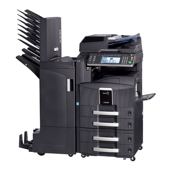
- Page 18 2KR/2KS 1-1-2 Parts names (1) Machine Figure 1-1-1 Original cover (option) Original size indicator plates Clip holder Slit glass Attention indicator Receive indicator Left cover 1 Left cover 1 lever Left cover 2 10. Left cover 2 handle 11. Contact glass 12.
- Page 19 2KR/2KS Figure 1-1-2 15. Toner container stopper 16. Toner container 17. Waste toner box 18. Paper feed unit (A2) 19. Paper feed unit cover (A3) 20. Knob 1-1-5...
- Page 20 2KR/2KS OPT2 OPT1 Figure 1-1-3 21. USB memory slot (A1) 22. Front cover 23. Paper width adjusting tab 24. Paper length guide 25. Top tray 26. Main power switch 27. Paper width guide 28. MP tray (multi purpose tray) 29. Optional interface slot (OPT2) 30.
- Page 21 2KR/2KS (2) Operation panel 13 14 15 18 19 22 23 25 26 Figure 1-1-4 System menu key/indicator 14. Program key/indicator Counter key/indicator 15. Application key/indicator Help key/indicator 16. Document box key/indicator Print indicator 17. Accessibility key/indicator Send indicator 18. Send key/indicator Receive indicator 19.
- Page 22 2KR/2KS 1-1-3 Machine cross section Light path Paper path Figure 1-1-5 Machine cross section Cassette paper feed section Toner container section MP tray paper feed section Transfer and separation sections Image scanner section Fuser section Laser scanner section 10. Eject and switchback sections Drum section 11.
-
Page 23: Installation Environment
2KR/2KS 1-2 Installation 1-2-1 Installation environment ° ° Temperature: 10 to 32.5 C/50 to 90.5 Humidity: 15 to 80%RH Power supply: 120 V AC, 12 A 220 to 240 V AC, 6.3 A ± ± Power source frequency: 50 Hz 0.3%/60 Hz 0.3% Installation location... -
Page 24: Unpacking And Installation
2KR/2KS 1-2-2 Unpacking and installation (1) Installation procedure Start Unpack. Connect the power cord. Remove the tapes and pad. Installing toner. Install the optional paper feeder. Setting the delivery date Release the lever holding mirror 1 and 2 frames. (maintenance item U278). Output an own-status report Release of cassette lift plate. - Page 25 2KR/2KS Moving the machine When moving the machine, pull out the four handles on the right and left sides and hold them. Handle Handle Handle Handle Figure 1-2-2 1-2-3...
- Page 26 2KR/2KS-2 Unpacking. Figure 1-2-3 Unpacking Machine 11. Document tray Outer case 12. Power cord Inner frame 13. Plastic bag Skid 14. Operation guide Bottom left pad 15. Paper size plates Bottom right pad 16. Plastic bag Upper left pad 17. Cursor pins Upper right pad 18.
- Page 27 2KR/2KS Remove the tapes and pad. 1. Remove two tapes. 2. Remove the pad. O PT Tape Tape Figure 1-2-4 Install the optional paper feeder. 1. Install the optional paper feeder as necessary. 2. Verify levelness at the four corners of the platen using a level gauge, and adjust the level bolts at the bottom of the machine to optimize levelness.
- Page 28 2KR/2KS Release of cassette lift plate. Cassette 1. Pull cassette 1 and 2 out. Lift plate stopper Remove the lift plate stopper from each cas- sette and attach it to the storage location. When moving the machine, attach the lift plate in original position.
- Page 29 2KR/2KS 4. Align the paper flush against the left side of the cassette. Figure 1-2-9 Install the toner container. 1. Open the front cover. Toner container 2. Tap the top of the toner container five to six times. Figure 1-2-10 3.
- Page 30 2KR/2KS 4. Gently push the toner container into the machine along the rails. Toner container Push the container all the way into the machine until it locks in place. Figure 1-2-12 Install the waste toner box. 1. Install the waste toner box in the machine. 2.
- Page 31 2KR/2KS Installing toner. 1. Turn the main power switch on. Toner installation is started. 2. The drive chain is disengaged when toner installation is completed. Run maintenance mode U130 if [Add Toner] remains displayed even after the drive chain is disengaged. Setting the delivery date (maintenance item U278).
- Page 32 2KR/2KS (2) Setting initial copy modes Factory settings are as follows: Maintenance Contents Factory setting item No. U253 Switching between double and single counts DOUBLE COUNT(A3/LEDGER) U260 Selecting the timing for copy counting After ejection U285 Setting service status page U326 Setting the black line cleaning indication ON/8...
- Page 33 2KR/2KS-2 1-2-3 Installing the key counter (option) Installing the key counter requires the following component: Key counter (P/N 3025418011) Key counter set (P/N 302A369708) Supplied parts of key counter set: Key counter socket assembly (P/N 3029236241) Key counter cover (P/N 3066060011) Key counter mount (P/N 3066060041) Key counter retainer (P/N 302GR03020) Key counter cover retainer (P/N 302GR03010)
- Page 34 2KR/2KS 5. Remove the ISU filter cover. 6. Remove ten screws and then remove the ISU filter cover rear cover. Screws Screws Screw Rear cover Screws Figure 1-2-15 7. Remove two screws and then remove the scanner right cover. Screw Scanner right cover Screw Figure 1-2-16...
- Page 35 2KR/2KS 8. Remove three screws and then remove the right upper cover. 9. Cut out the aperture plate on the right upper cover using nippers. Screw Right upper cover Aperture Screw Screw Figure 1-2-17 10. Release the wire saddle and then stretch the key counter wire.
- Page 36 2KR/2KS 12. Refit the rear cover and ISU filter cover. 13. Pass the key counter wire through the aper- ture and then refit the upper right cover. Aperture Upper right cover Key counter wire Figure 1-2-19 14. Pass the connector of the key counter wire Right upper cover through the aperture in the key counter cover retainer.
- Page 37 2KR/2KS 18. Connect the connector of the key counter Key counter signal cable to the connector of the key cover retainer counter wire. 19. Fit the key counter cover with the key counter socket assembly inserted to the key counter cover retainer using the M4 x 6 screw.
- Page 38 2KR/2KS 1-2-4 Replacing the expanded memory Procedure Clamp 1. Press the power key on the operation panel Protrusion to off. Make sure that the main power indica- tor and the memory indicator are off before turning off the main power switch. And then Memory socket unplug the power cable from the wall outlet.
-
Page 39: Maintenance Mode
2KR/2KS 1-3 Maintenance Mode 1-3-1 Maintenance mode The machine is equipped with a maintenance function which can be used to maintain and service the machine. (1) Executing a maintenance item Start Enter 10871087 using Maintenance mode is entered. the numeric keys. Enter the maintenance item number using the cursor up/down keys The maintenance item is... - Page 40 2KR/2KS-2 (2) Maintenance modes item list Item Initial Section Content of maintenance item setting* General U000 Outputting an own-status report U001 Exiting the maintenance mode U002 Setting the factory default data U003 Setting the service telephone number *************** U004 Displaying the machine number U019 Displaying the ROM version Initialization...
- Page 41 2KR/2KS-2 Item Initial Section Content of maintenance item setting* Optical U099 Adjusting original size detection 40/30/20/40/30/20/40/30/20/ 19/19/19/150 (DP not installed) 50/50/50/50/50/50/50/50/50/ 49/49/49/150 (DP installed) High voltage U100 Setting the main high voltage U101 Setting the other high voltages Developing bias AC component frequency at image formation Developing shift bias potential at image formation Developing bias AC component duty at image formation Transfer control voltage...
- Page 42 2KR/2KS-1 Item Initial Section Content of maintenance item setting* Operation U208 Setting the paper size for the paper feeder Inch specifications: Letter panel and Metric specifications: A4 support U221 Setting the USB host lock function equipment U222 Setting the IC card type U223 Operation panel lock Unlock...
- Page 43 2KR/2KS-2 Item Initial Section Content of maintenance item setting* Image U425 Setting the target processing U470 Setting the JPEG compression ratio System 90/90 Copy 90/90/90/90 Send 30/40/51/70/90 30/40/51/70/90 30/40/51/70/90 30/40/51/70/90 15/25/60 15/25/60 U473 Adjusting laser power output U485 Setting the image processing mode Network U510 Setting the enterprise mode...
- Page 44 2KR/2KS (3) Contents of the maintenance mode items Maintenance Description item No. Outputting an own-status report U000 Description Outputs lists of the current settings of the maintenance items, and paper jam and service call occurrences. Outputs the event log or service status page. Also sends output data to the USB memory. Printing a report is disabled either when a job is remaining in the buffer or when [Pause All Print Jobs] is pressed to halt printing.
-
Page 45: Event Log
2KR/2KS Maintenance Description item No. U000 Event log Event Log Firmware version 2KS_2000.001.001 2009.06.17 Paper Jam Log Service Call Log Count. Event Count. Service Code Descriprions 1881214 F0.0030 1876543 178944 01.1010 10.01.08.01.01 166554 10.01.08.01.02 5296 F0.4000 4988 10.01.08.01.01 5295 F0.3100 4988 10.01.08.01.02 2099... - Page 46 2KR/2KS Maintenance Description item No. U000 Detail of event log Items Description System version System date Paper Jam Log Count. Event Remembers 1 to 16 of The total page count at Log code (2 digit, hexa- occurrence. If the the time of the paper decimal, 5 categories) occurrence of the previ- jam.
- Page 47 2KR/2KS Maintenance Description item No. U000 Items Description Paper Jam Log 82: Jam in stapler cont. 83: Exit sensor stay jam 84: Jam in eject section of right sub tray (3000-sheet document finisher) 85: Jam in eject section of left sub tray (3000-sheet document finisher) 86: Jam in eject section of internal tray 1 (3000-sheet document finisher) 87: Jam in eject section of internal tray 2 (3000-sheet document finisher) 88: Jam in eject section of main tray (3000-sheet document finisher)
- Page 48 2KR/2KS-1 Maintenance Description item No. U000 Items Description Paper Jam Log (e) Detail of paper exit location (Hexadecimal) cont. 01: Face down (FD) 02: Face up (FU)/ Document finisher face up (FU)/ 3000-sheet document finisher left sub tray (FU) 03: Document finisher face down (FD) 04: Reserved 05: Reserved 06: 3000-sheet document finisher right sub tray (FU)
- Page 49 2KR/2KS Maintenance Description item No. U000 Items Description Unknown Toner Log Count. Item Remembers 1 to 5 of The total page count at Unknown toner log occurrence of unknown the time of the [Toner code (1 byte, 2 catego- toner detection. If the Empty] error with using ries) occurrence of the previ-...
-
Page 50: Service Status Page
2KR/2KS-1 Maintenance Description item No. U000 Service status page (1) Service Status Page 17/06/2009 08:40 Firmware version 2KS_2000.000.000 2009.06.17 [XXXXXXXX] [XXXXXXXX] [XXXXXXXX] Controller Information Memory status FRPO Status (28) Total Size 1.0 GB Default Pattern Switch Default Font Number C5*10000+C2*100+C3 00000 Time Local Time Zone... -
Page 51: Engine Information
2KR/2KS-1 Maintenance Description item No. U000 Service status page (2) Service Status Page 17/06/2009 08:40 Firmware version 2KS_2000.000.000 2009.06.17 [XXXXXXXX] [XXXXXXXX] [XXXXXXXX] Engine Information Send Information (30) NVRAM Version _Bb04B29_Bb04B29 (31) Scanner Version 2KS_1200.001.089 (34) Date and Time 09/06/17 (32) FAX Slot1 (35) Address... - Page 52 2KR/2KS-1 Maintenance Description item No. U000 Detail of service status page Description Supplement System version System date Engine soft version Engine boot version Operation panel mask version Total RAM size Local time zone Report output date Day/Month/Year hour:minute NTP server name (10) Presence or absence of the optional Installed/Not Installed...
- Page 53 2KR/2KS-1 Maintenance Description item No. U000 Description Supplement (30) NV RAM version _ Bb 04B29 _ Bb 04B29 (a) (b) (d) (e) (a) Consistency of the present software version and the database _ (underscore): OK * (Asterisk): NG (b) Database version (c) The oldest time stamp of database version (d) Consistency of the present software version and the ME firmware version...
- Page 54 2KR/2KS-1 Maintenance Description item No. U000 Description Supplement (49) Fixed assets number (50) Job complete judgment timeout time setting for local interface (51) Media type attributes Weight settings 1 to 28 (Not used: 18, 19, 20) 0: Light/1: Normal 1 / 2: Normal 2 / 3: Normal 3/ 4: Heavy 1 / 5: Heavy 2 / 6: Heavy 3 / 7: Extra Heavy Fuser settings 0: High / 1: Middle / 2: Low / 3: Vellum...
- Page 55 2KR/2KS Maintenance Description item No. Setting the service telephone number U003 Description Sets the telephone number to be displayed when a service call code is detected. Purpose To set the telephone number to call service when installing the machine. Method Press the start key.
- Page 56 2KR/2KS Maintenance Description item No. Displaying the ROM version U019 Description Displays the part number of the ROM fitted to each PWB. Purpose To check the part number or to decide, if the newest version of ROM is installed. Method 1.
- Page 57 2KR/2KS Maintenance Description item No. Initializing counters and mode settings U021 Description Initializes all settings, except those pertinent to the type of machine, namely each counter, service call history and mode setting. Also initializes backup RAM according to region specification selected in maintenance item U252 Setting the destination.
- Page 58 2KR/2KS Maintenance Description item No. Checking motor operation U030 Description Drives each motor. Purpose To check the operation of each motor. Method 1. Press the start key. 2. Select the motor to be operated. 3. Press the start key. The operation starts. Display Operation MAIN...
- Page 59 2KR/2KS Maintenance Description item No. Checking clutch operation U032 Description Turns each clutch on. Purpose To check the operation of each clutch. Method 1. Press the start key. 2. Select the clutch to be operated. 3. Press the start key. The clutch turns on for 1 s. Display Clutches Paper feed clutch 1 (PFCL1)
- Page 60 2KR/2KS-1 Maintenance Description item No. Adjusting the print start timing U034 Description Adjusts the leading edge registration or center line. Purpose Make the adjustment if there is a regular error between the leading edges of the copy image and original. Make the adjustment if there is a regular error between the center lines of the copy image and original.
- Page 61 2KR/2KS-1 Maintenance Description item No. Caution U034 Check the copy image after the adjustment. If the image is still incorrect, perform the following adjustments in maintenance mode. U066 U071 U034 (P.1-3-29) (P.1-3-34) Adjustment: Center line adjustment 1. Select the item to be adjusted. Display Description Setting...
- Page 62 2KR/2KS Maintenance Description item No. Caution U034 Check the copy image after the adjustment. If the image is still incorrect, perform the following adjustments in maintenance mode. U067 U072 U034 (P.1-3-30) (P.1-3-36) Completion Press the stop key. The screen for selecting a maintenance item No. is displayed. Setting the printing area for folio paper U035 Description...
- Page 63 2KR/2KS-2 Maintenance Description item No. Adjusting the deflection in the paper U051 Description Adjusts the deflection in the paper. Purpose Make the adjustment if the leading edge of the copy image is missing or varies randomly, or if the copy paper is Z-folded.
- Page 64 2KR/2KS-2 Maintenance Description item No. Adjustment U053 1. Press the system menu key. 2. Press the start key to output an A3/Ledger VTC pattern. Correct values for an A3/Ledger output are: ± A = 350 1.4 mm ± B = 250 1.0 mm Figure 1-3-7 3.
- Page 65 2KR/2KS Maintenance Description item No. Turning the exposure lamp on U061 Description Turns the exposure lamp on. Purpose To check the exposure lamp. Method 1. Press the start key. 2. Select the item. Display Description The exposure lamp lights The CIS lights (when dual scan DP is installed) 3.
- Page 66 2KR/2KS Maintenance Description item No. Adjusting the scanner magnification U065 Description Adjusts the magnification of the original scanning. Purpose Make the adjustment if the magnification in the main scanning direction is incorrect. Make the adjustment if the magnification in the auxiliary scanning direction is incorrect. Caution Adjust the magnification of the scanner in the following order.
- Page 67 2KR/2KS Maintenance Description item No. Completion U065 Press the stop key. The screen for selecting a maintenance item No. is displayed. Adjusting the scanner leading edge registration U066 Description Adjusts the scanner leading edge registration of the original scanning. Purpose Make the adjustment if there is a regular error between the leading edges of the copy image and original.
- Page 68 2KR/2KS Maintenance Description item No. Adjusting the scanner center line U067 Description Adjusts the scanner center line of the original scanning. Purpose Make the adjustment if there is a regular error between the center lines of the copy image and original. Adjustment 1.
- Page 69 2KR/2KS Maintenance Description item No. Adjusting the scanning position for originals from the DP U068 Description Adjusts the position for scanning originals from the DP. Performs the test copy at the four scanning positions after adjusting. Purpose Used when the image fogging occurs because the scanning position is not proper when the DP is used. Run U071 to adjust the timing of DP leading edge when the scanning position is changed.
- Page 70 2KR/2KS Maintenance Description item No. Adjusting the DP magnification U070 Description Adjusts the DP original scanning speed. Purpose Make the adjustment if the magnification is incorrect in the main scanning direction or auxiliary scanning direction when the DP is used. Method 1.
- Page 71 2KR/2KS Maintenance Description item No. Adjustment: Auxiliary scanning direction of CCD/CIS U070 1. Press the system menu key. 2. Place an original on the DP and press the start key to make a test copy. 3. Press the system menu key. 4.
- Page 72 2KR/2KS Maintenance Description item No. Adjusting the DP scanning timing U071 Description Adjusts the DP original scanning timing. Purpose Make the adjustment if there is a regular error between the leading or trailing edges of the original and the copy image when the DP is used. Method 1.
- Page 73 2KR/2KS Maintenance Description item No. Adjustment: Trailing edge registration U071 1. Press the system menu key. 2. Place an original on the DP and press the start key to make a test copy. 3. Press the system menu key. 4. Change the setting value using the +/- or numeric keys. For copy example 1, increase the value.
- Page 74 2KR/2KS Maintenance Description item No. Adjusting the DP center line U072 Description Adjusts the scanning start position for the DP original. Purpose Make the adjustment if there is a regular error between the centers of the original and the copy image when the DP is used.
- Page 75 2KR/2KS Maintenance Description item No. Checking scanner operation U073 Description Simulates the scanner operation under arbitrary conditions. Purpose To check scanner operation. Start 1. Press the start key. 2. Select the item to be operated. Display Description SCANNER MOTOR Scanner operation HOME POSITION Home position operation DUST CHECK...
- Page 76 2KR/2KS-1 Maintenance Description item No. Adjusting the DP input light luminosity U074 Description Sets the luminosity correction for scanning originals from the DP. Purpose Modify the setting only if a spotted background appears when a bluish original is scanned from the DP. Setting 1.
- Page 77 2KR/2KS Maintenance Description item No. Adjusting the correct exposure U081 Description Adjusts the correct exposure in text and photo mode, text mode or photo mode. Purpose To be executed as required. Setting 1. Press the start key. 2. Select the item to be set. 3.
- Page 78 2KR/2KS Maintenance Description item No. Outputting a MIP-PG pattern U089 Description Selects and outputs the MIP-PG pattern created in the machine. Purpose To check copier status other than scanner when adjusting image printing, using MIP-PG pattern output (with- out scanning). Method 1.
- Page 79 2KR/2KS-1 Maintenance Description item No. Setting the white line correction U091 Description Sets the error detection threshold value for white line correction and displays the count result of abnormal pixels. Purpose To perform when replacing the CIS, DP driver PWB or CIS roller. Method: white line correction 1.
- Page 80 2KR/2KS-1 Maintenance Description item No. U091 3. Press the start key. The value is set. 4. After changing the Threshold(Com) value, turn the main power switch off and on. Completion Press the stop key. The screen for selecting a maintenance item No. is displayed. Setting the exposure density gradient U093 Description...
- Page 81 2KR/2KS-1 Maintenance Description item No. Setting: [MIXED] U093 1. Select the item to be set. 2. Adjust the setting using the +/- or numeric keys. Display Description Setting Initial range setting MIXED DARKER Change in density when manual density is set dark 0 to 3 MIXED LIGHTER Change in density when manual density is set light 0 to 3 Increasing the setting makes the change in density larger, and decreasing it makes the change smaller.
- Page 82 2KR/2KS Maintenance Description item No. Adjusting original size detection U099 Description Checks the operation of the original size sensor and sets the sensing threshold value. Purpose To adjust the sensitiveness of the sensor and size judgement time if the original size sensor malfunctions fre- quently due to incident light or the like.
- Page 83 2KR/2KS Maintenance Description item No. Setting the main high voltage U100 Description Performs main charging. Purpose To check main charging. Method 1. Press the start key. 2. Select the item to be operated. 3. Press the start key. The selected operation starts. Display Description Turning the main charger on...
- Page 84 2KR/2KS Maintenance Description item No. Setting the cleaning interval for the main charger U102 Description Changes the intervals at which the main charger is cleaned. Purpose To change the setting when the background is visible. Setting 1. Press the start key. 2.
- Page 85 2KR/2KS Maintenance Description item No. Setting toner refresh operation U112 Description Sets the toner refresh operation time and the developing bias on time at power on and after copying. Purpose To change the toner refresh operation time and the developing bias on time at power on and after copying if image flow level is low.
- Page 86 2KR/2KS Maintenance Description item No. Checking the drum number U117 Description Displays the drum number. Purpose To check the drum number. Method 1. Press the start key. The drum number is displayed. Completion Press the stop key. The screen for selecting a maintenance item No. is displayed. Displaying the drum history U118 Description...
- Page 87 2KR/2KS Maintenance Description item No. Initial setting for the developing unit U130 Description Replenishes toner to the developing unit to a certain level from the toner container that has been installed. Purpose To operate when installing the machine or replacing the developing unit. Method 1.
- Page 88 2KR/2KS-2 Maintenance Description item No. Setting toner disposal operation U144 Description Sets toner disposal operation after completion of copying. Purpose To set whether or not toner is disposal on the drum after low density copying. Normally no change is neces- sary from the initial setting.
- Page 89 2KR/2KS-2 Maintenance Description item No. Checking the developing drive time U157 Description Displays the developing drive time for checking, which is used as a reference when correcting the toner con- trol. Purpose To check the developing drive time after replacing the developing unit. Method 1.
- Page 90 2KR/2KS-2 Maintenance Description item No. Completion U161 Press the stop key. The screen for selecting a maintenance item No. is displayed. Resetting the fuser problem data U163 Description Resets the detection of a service call code indicating a problem in the fuser section. Purpose To prevent accidents due to an abnormally high fuser temperature.
- Page 91 2KR/2KS-2 Maintenance Description item No. Setting the fuser phase control U198 Description Enables or disables fuser-phase control. Purpose Turn to OFF to reduce the audible sound that may be generated by the power source PWB. Depending on the environment of installation, this may cause a voltage drop, potentially resulting in flickering fluorescent tubes, etc.
- Page 92 2KR/2KS Maintenance Description item No. Initializing the touch panel U201 Description Automatically correct the positions of the X- and Y-axes of the touch panel. Purpose To automatically correct the display positions on the touch panel after it is replaced. Method 1.
- Page 93 2KR/2KS Maintenance Description item No. Checking DP operation U203 Description Simulates the original conveying operation separately in the DP. Purpose To check the DP operation. Method 1. Press the start key. 2. Place an original in the DP if running this simulation with paper. 3.
- Page 94 2KR/2KS Maintenance Description item No. Setting the presence or absence of a key card or key counter U204 Description Sets the presence or absence of the optional key card or key counter. Purpose To run this maintenance item if a key card or key counter is installed. Method 1.
- Page 95 2KR/2KS Maintenance Description item No. Checking the operation panel keys U207 Description Checks operation of the operation panel keys. Purpose To check operation of all the keys and LEDs on the operation panel. Method 1. Press the start key. The screen for executing is displayed. 2.
- Page 96 2KR/2KS-1 Maintenance Description item No. Setting the USB host lock function U221 Description Specifies ON/OFF the USB host lock function. Setting this to ON causes the machine to be unable to recog- nize the device connected to the USB host. Purpose Set according to the preference of the user.
- Page 97 2KR/2KS-1 Maintenance Description item No. Operation panel lock U223 Description Sets the operation panel lock function to ON or OFF. Purpose To restrict operation in the system menu on the operation panel. Setting 1. Press the start key. 2. Select the item. Display Description Unlock...
- Page 98 2KR/2KS-1 Maintenance Description item No. Setting punch destination U234 Description Sets the destination of punch unit of 3000-sheet document finisher. Purpose To be set when installing a different punch unit from the destination of the machine. Setting 1. Press the start key. 2.
- Page 99 2KR/2KS Maintenance Description item No. Setting finisher stack quantity U237 Description Sets the number of sheets of each stack on the main tray and on the Inner tray in 3000-sheet document fin- isher. Purpose To change the setting when a stack malfunction has occurred. Method 1.
- Page 100 2KR/2KS Maintenance Description item No. Checking the operation of the finisher U240 Description Turns each motor and solenoid of the 3000-sheet document finisher ON. Purpose To check the operation of each motor and solenoid of the 3000-sheet document finisher. Method 1.
- Page 101 2KR/2KS Maintenance Description item No. Method: [FINISHER SOL] U240 1. Select the item to be operated. 2. Press the start key. The operation starts. Display Solenoid FEED IN SOL Paper entry solenoid (PESOL) REAR DOWN SOL 1 Trailing edge holder solenoid 1 (TEHSOL1) REAR DOWN SOL 2 Trailing edge holder solenoid 2 (TEHSOL2) SUB PATH SOL...
- Page 102 2KR/2KS Maintenance Description item No. Checking the operation of the switches of the finisher U241 Description Displays the status of each switch of 3000-sheet document finisher. Purpose To check the operation of each switch of 3000-sheet document finisher. Method 1. Press the start key. 2.
- Page 103 2KR/2KS Maintenance Description item No. Method: [MAIL BOX] U241 1. Turn each switch or sensor on and off manually to check the status. When the on-status of a switch or sensor is detected, that switch or sensor is displayed in reverse. Display Switches and sensors HP SW...
- Page 104 2KR/2KS Maintenance Description item No. Checking the operation of the DP motors U243 Description Turns the motors or solenoids in the DP on. Purpose To check the operation of the DP motors and solenoids. Method 1. Press the start key. 2.
- Page 105 2KR/2KS Maintenance Description item No. Checking messages U245 Description Displays a list of messages on the touch panel of the operation panel. Purpose To check the messages to be displayed. Method 1. Press the start key. 2. Select the item to be displayed. 3.
- Page 106 2KR/2KS Maintenance Description item No. Setting: Adjustment of registration stop timing U246 1. Select [PUNCH REG ADJ]. 2. Change the setting value using the cursor up/down keys. Setting Initial Change in Description range setting value per step Adjustment of registration stop timing -20 to 20 1 ms If skewed paper conveying occurs (sample 1), increase the preset value.
- Page 107 2KR/2KS Maintenance Description item No. Setting: Adjustment of front and back stapling home position U246 1. Select [STAPLE HP ADJ]. 2. Change the setting using the +/- or numeric keys. Setting Initial Change in Description range setting value per step Adjustment of front and back stapling home position -10 to 10 0.32 mm When staple positions are off toward the front side of the machine (sample 1), increase the preset value.
- Page 108 2KR/2KS Maintenance Description item No. Setting: [BOOKLET FOLDER] U246 1. Select the item to be set. Display Description WIDTH U HP ADJ Adjustment of upper side registration home position WIDTH L HP ADJ Adjustment of lower side registration home position STAPLE POS ADJ (A4R/LTR) Adjustment of booklet stapling position for A4/Letter size STAPLE POS ADJ (B4R/LGR)
- Page 109 2KR/2KS Maintenance Description item No. Setting: Adjustment of center folding position U246 1. Select [SADDLE POS ADJ (A4R/LTR)], [SADDLE POS ADJ (B4R/LGR)] or [SADDLE POS ADJ (A3/LD)]. 2. Change the setting using the +/- or numeric keys. Setting Initial Change in Description range setting...
- Page 110 2KR/2KS Maintenance Description item No. Setting the paper feed device U247 Description Turns on motors and clutches of 3000-sheet paper feeder or paper feeder. Purpose To check the operation of motors and clutches of paper feed device. Method 1. Press the start key. The value varies depending to the option furnished. 2.
- Page 111 2KR/2KS Maintenance Description item No. Setting the maintenance cycle U250 Description Changes preset values for maintenance cycle and automatic grayscale adjustment. Purpose Provides changing the time when the message to acknowledge to conduct maintenance and automatic gray- scale adjustment is periodically displayed. Setting 1.
- Page 112 2KR/2KS-2 Maintenance Description item No. Setting the destination U252 Description Switches the operations and screens of the machine according to the destination. Purpose To be executed after initializing the backup RAM, in order to return the setting to the value before replacement or initialization.
- Page 113 2KR/2KS Maintenance Description item No. Switching between double and single counts U253 Description Switches the count system for the total counter and other counters. Purpose Used to select, according to the preference of the user (copy service provider), if A3/Ledger paper is to be counted as one sheet (single count) or two sheets (double count).
- Page 114 2KR/2KS Maintenance Description item No. Setting OEM purchaser code U265 Description Sets the OEM purchaser code. Purpose Sets the code when replacing the main PWB and the like. Setting 1. Press the start key. 2. Change the preset value using the numeric keys. 3.
- Page 115 2KR/2KS Maintenance Description item No. Setting the black line cleaning indication U326 Description Sets whether to display the cleaning guidance when detecting the black line. Purpose Displays the cleaning guidance in order to make the call for service with the black line decrease by the rubbish on the contact glass when scanning from the DP.
- Page 116 2KR/2KS Maintenance Description item No. Side ejection setting U328 Description Sets whether to eject to the side of the machine when an optional curl eliminator is installed. Purpose Set according to the preference of the user. Setting 1. Press the start key. 2.
- Page 117 2KR/2KS Maintenance Description item No. Specific paper feed location setting for printing function U341 Description Sets a paper feed location specified for printer output. Purpose To use a paper feed location only for printer output. A paper feed location specified for printer output cannot be used for copy output. Method 1.
- Page 118 2KR/2KS Maintenance Description item No. Switching between duplex/simplex copy mode U343 Description Switches the initial setting between duplex and simplex copy. Purpose To be set according to frequency of use: set to the more frequently used mode. Setting 1. Press the start key. 2.
- Page 119 2KR/2KS-1 Maintenance Description item No. Adjusting margins of image printing U402 Description Adjusts margins for image printing. Purpose Make the adjustment if margins are incorrect. Adjustment 1. Press the start key. 2. Select the item to be adjusted. Setting Initial Change in Display Description...
- Page 120 2KR/2KS Maintenance Description item No. Adjusting margins for scanning an original on the platen U403 Description Adjusts margins for scanning the original on the contact glass. Purpose Make the adjustment if margins are incorrect. Adjustment 1. Press the start key. 2.
- Page 121 2KR/2KS Maintenance Description item No. Adjusting margins for scanning an original from the DP U404 Description Adjusts margins for scanning the original from the DP. Purpose Make the adjustment if margins are incorrect when the DP is used. Caution Before making this adjustment, ensure that the following adjustments have been made in maintenance mode. U402 U403 U404...
- Page 122 2KR/2KS-1 Maintenance Description item No. Adjusting the leading edge registration for memory image printing U407 Description Adjusts the leading edge registration during memory copying. Purpose Make the following adjustment if there is a regular error between the leading edge of the copy image on the front face and that on the reverse face during duplex switchback copying.
- Page 123 2KR/2KS Maintenance Description item No. Adjusting the halftone automatically U410 Description Carries out processing for the data acquisition that is required in order to perform automatic adjustment of the halftone. Purpose Performed when the quality of reproduced halftones has dropped. Method 1.
- Page 124 2KR/2KS Maintenance Description item No. Adjusting the scanner automatically U411 Description Uses a specified original and automatically adjusts the following items in the scanner and the DP scanning sections. Purpose To perform automatic adjustment of various items in the scanner and the DP scanning sections. Method 1.
- Page 125 2KR/2KS Maintenance Description item No. Method: [DP(FACE UP)] U411 1. Measure the leading edge, main scanning, and auxiliary scanning of the specified original (P/N: 302AC68243) and enter the values by executing maintenance item U425. 2. Set a specified original (P/N: 302AC68243) in the DP. Cut the trailing edge of the original. 5 mm 149 ±...
- Page 126 2KR/2KS Maintenance Description item No. [INPUT] U411 1. Select [INPUT]. 2. Place a specified original (P/N: 302AC68243). 3. Press the start key. Auto adjustment starts. [MTF/GAMMA] 1. Select [MTF/GAMMA]. 2. Place a specified original (P/N: 303JX57010). 3. Press the start key. Auto adjustment starts. [MATRIX] 1.
- Page 127 2KR/2KS Maintenance Description item No. Error Codes U411 Codes Description ERROR 01 Black band detection error (scanner leading edge registration) ERROR 02 Black band detection error (scanner center line) ERROR 03 Black band detection error (scanner main scanning direction magnification) ERROR 04 Black band is not detected (scanner leading edge registration) ERROR 05...
- Page 128 2KR/2KS Maintenance Description item No. Setting the target U425 Description Enters the lab values that is indicated on the back of the chart (P/N: 302FZ56990) used for adjustment. Also enters the measurement value of the chart (P/N: 302AC68243) used for adjustment. Purpose Performs data input in order to correct for differences in originals during automatic adjustment.
- Page 129 2KR/2KS Maintenance Description item No. Setting: [ADJUST ORIGINAL] U425 1. Measure the distance from the left edge to the black belt (a) of the original at A, B and C. Measurement procedure 1) Measure the distance from the edge to the black belt (a) of the original at A (35 mm from the leading edge), B (110 mm from the leading edge) and C (185 mm from the leading edge), respectively.
- Page 130 2KR/2KS Maintenance Description item No. Setting: [DP] U425 1. Measure the distance from the leading edge to the black belt (inside) of the original at A. 2. Enter the measured value using the +/- keys in [LEAD]. 3. Measure the distance from the left edge to the black belt (inside) of the original at B. 4.
- Page 131 2KR/2KS Maintenance Description item No. Setting the JPEG compression ratio U470 Description Sets the compression ratio for JPEG images in each image quality mode. Purpose To change the setting in accordance with the image that the user is copying. For example, in order to soften the coarseness of the image when making copies at over 200% magnification, change the level of compres- sion by raising the value.
- Page 132 2KR/2KS-1 Maintenance Description item No. Supplement U470 While this maintenance item is being executed, copying from an original is available in interrupt copying mode (which is activated by pressing the system menu key). Completion Press the stop key. The screen for selecting a maintenance item No. is displayed. Adjusting laser power output U473 Description...
- Page 133 2KR/2KS-2 Maintenance Description item No. Setting: [PDF Rotate] U485 1. Change the setting value using +/- or numeric keys. Display Description Assigns the image rotation with the internal parameter Assigns the image rotation with the actual image Initial setting: 0 2.
- Page 134 2KR/2KS-1 Maintenance Description item No. Checking/clearing copy counts by paper feed locations U901 Description Displays or clears copy counts by paper feed locations. Purpose To check the time to replace consumable parts. Also to clear the counts after replacing the consumable parts. Method 1.
- Page 135 2KR/2KS-1 Maintenance Description item No. Checking/clearing the paper jam counts U903 Description Displays or clears the jam counts by jam locations. Purpose To check the paper jam status. Also to clear the jam counts after replacing consumable parts. Method 1. Press the start key. 2.
- Page 136 2KR/2KS Maintenance Description item No. Checking/clearing counts by optional devices U905 Description Displays the counts of DP or finisher. Purpose To check the use of DP and finisher. Method 1. Press the start key. 2. Select the device, the count of which is to be checked. 3.
- Page 137 2KR/2KS Maintenance Description item No. Checking the total counter value U908 Description Displays the total counter value. Purpose To check the total counter value. Method 1. Press the start key. The screen for total count value is displayed. Completion Press the stop key. The screen for selecting a maintenance item No. is displayed. Clearing the black ratio data U910 Description...
- Page 138 2KR/2KS-1 Maintenance Description item No. Setting backup data reading/writing U917 Description Retrieves the backup data to a USB memory from the machine; or writes the data from the USB memory to the machine. Purpose To store and write data when replacing the HDD. Method 1.
- Page 139 2KR/2KS-1 Maintenance Description item No. Error Codes U917 Codes Description Codes Description 321e0001 Parameter error 321e002f Box open error 321e0002 File write error 321e0030 Box close error 321e0003 File initialization error 321e0031 Box creation error 321e0004 File error 321e0032 Box creation error 321e0005 Processing error 321e0033...
- Page 140 2KR/2KS Maintenance Description item No. Checking the copy counts U920 Description Checks the copy counts. Purpose To check the copy counts. Method 1. Press the start key. The current counts are displayed. Display Description Copy Count Count value of copy Printer Count Count value of printer Fax Count...
- Page 141 2KR/2KS Maintenance Description item No. Setting the automatic toner install U931 Description Sets automatic toner installation on or off when power is turned on. Purpose Changed to off when deactivating automatic toner installation. Setting 1. Press the start key. 2. Select ON or OFF. Display Description Automatic toner install function ON...
- Page 142 2KR/2KS Maintenance Description item No. Setting of deflection for feeding from DP U942 Description Adjusts the deflection generated when the DP is used. Purpose Use this mode if an original non-feed jam, oblique feed or wrinkling of original occurs when the DP is used. Setting 1.
- Page 143 2KR/2KS Maintenance Description item No. Checking of toner area code U969 Description Displays the toner area code. Purpose To check the toner area code. Method 1. Press the start key. The toner area code is displayed. Completion Press the stop/clear key. The screen for selecting a maintenance item No. is displayed. Data capture mode U977 Description...
- Page 144 2KR/2KS Maintenance Description item No. HDD scandisk U989 Description Restores data in the hard disk by scanning the disk. Purpose If power is turned off while accessing to the hard disk is performed, the control information in the hard disk drive may be damaged.
-
Page 145: Management Mode
2KR/2KS 1-3-2 Management mode In addition to a maintenance function for service, the machine is equipped with a management function which can be oper- ated by users (mainly by the administrator). In this management mode, settings such as default settings can be changed. (1) Using the management mode Start Press the System Menu key. - Page 146 2KR/2KS (2) Common Settings Paper Size and Media Type Setup for Multi Purpose Tray 1. Press [Next] of Original/Paper Settings, [Next] of Switching the Language for Display [Language] MP Tray Setting and then [Change] of Paper Size. 1. Press [Change] of Language. 2.
- Page 147 2KR/2KS Paper Source for Cover Paper Continuous Scan 1. Press [Next] of Original/Paper Settings, cursor 1. Press cursor down key, [Next] of Function Defaults down key and then [Change] of Paper Source for and then [Change] of Continuous Scan. Cover. 2.
- Page 148 2KR/2KS Zoom Auto Image Rotation 1. Press cursor down key, [Next] of Function Defaults, 1. Press cursor down key, [Next] of Function Defaults, cursor down key and then [Change] of Zoom. cursor down key and then [Change] of Auto Image 2.
- Page 149 2KR/2KS JPEG/TIFF Print (4) Sending Settings 1. Press cursor down key, [Next] of Function Defaults, cursor down key twice and then [Change] of JPEG/ Quick Setup Registration TIFF Print. 1. Press [Next] of Quick Setup Registration. 2. Select the default for [Fit to Paper Size], [Image 2.
- Page 150 2KR/2KS (6) Printer Settings LF Action 1. Press cursor down key and [Change] of LF Action. 2. Press [LF Only], [LF and CR] or [Ignore LF]. Emulation 3. Press [OK]. 1. Press [Change] of Emulation. 2. Select the desired emulation. 3.
- Page 151 2KR/2KS (8) Adjustment/Maintenance Gray Adjustment 1. Press cursor down key and then [Next] of Gray Copy Density Adjustment Adjustment. 1. Press [Next] of Copy Density Adjustment. 2. Press [Execute]. A color pattern is printed. 2. Press [Change] of Auto or of Manual. 3.
- Page 152 2KR/2KS Time Zone (10) Editing Destination (Address Book/Adding One 1. Press [Change] of Time Zone. Touch Keys) 2. Select the location. 3. Press [Off] or [On] of Summer Time and press [OK]. Adding a Contact 1. Press [Register/Edit] of Address Book, [Add], [Con- tact] and then [Next].
- Page 153 2KR/2KS Editing a Destination Deleting the Registered Information 1. Press [Register/Edit] of Address Book. 1. Press [Delete]. 2. Select a destination or group to edit. 2. Press [Yes] on the screen to confirm the deletion 3. Press [Detail]. of the data registered in the One Touch Key. The procedure differs depending on the details to be edited.
- Page 154 2KR/2KS (12) Applications (13) System Settings Installing Applications Restarting the System 1. Insert the USB memory containing the application 1. Press [Execute] of Restart. to be installed into the USB memory slot (A1). 2. When the confirmation screen appears, press 2.
- Page 155 2KR/2KS RA (Stateless) Settings SSL Setup 1. Press [Next] of Network and then [Next] of TCP/IP 1. Press [Next] of Network, [Next] of Secure Protocol, Setting. and then [Next] of SSL. 2. Press [Next] of IPv6. 2. Press [On] or [Off]. 3.
- Page 156 2KR/2KS Interface Block Setting (14) User Login Administration USB Host (USB memory slot setting) Enabling/Disabling User Login Administration 1. Press [Next] of Interface Block Setting and then 1. If user login administration is disabled, the user [Change] of USB Host. authentication screen appears.
- Page 157 2KR/2KS Changing User Properties Obtain Network User Property 1. If user login administration is disabled, the user 1. If user login administration is disabled, the user authentication screen appears. Enter your login authentication screen appears. Enter your login user name and password and then press [Login]. user name and password and then press [Login].
- Page 158 2KR/2KS Managing Accounts 2. Press [Next] of Job Accounting Setting, [Next] of 1. If user login administration is disabled, the user Default Setting and then [Next] of Default Counter authentication screen appears. Enter your login Limit. user name and password and then press [Login]. 3.
- Page 159 2KR/2KS 1-4 Troubleshooting 1-4-1 Paper misfeed detection (1) Paper misfeed indication When a paper misfeed occurs, the machine immediately stops copying and displays the jam location on the operation panel. Paper misfeed counts sorted by the detection condition can be checked in maintenance item U903. To remove paper jammed in the machine, open the front cover, left cover or pull the cassette out.
- Page 160 2KR/2KS (2) Paper misfeed detection conditions TULSW ORSW OFSW DPTSW2 SBTSW Document processor DPTSW1 OESW Built-in finisher PCSW FSSW PCSW MPFCL FCL1 FSW1 MPPFCL MPFSW PFCL1 FCL2 FSW2 PFCL2 FCL3 FSW3 PFPFCL1 PFPFCL2 PFPFCL1 PPS1 PPS2 PPS3 PFCCL PFFSW PFPFCL2 Paper feeder 3000-sheet paper feeder Figure 1-4-2...
- Page 161 2KR/2KS-1 Section Description Conditions Specified time System The power is turned on when a sensor in the conveying Initial JAM system is on. Cover is open during copying. Cover open Secondary paper feed does not start within specified time 40 s Secondary paper feed of arrival of paper at the registration section.
- Page 162 2KR/2KS-1 Section Description Conditions Specified time Paper The registration switch (RSW) does not turn on within spec- 1283 ms feed Misfeed in vertical ified time of feed switch 1 (FSW1) turning on. section paper conveying sec- Feed switch 1 (FSW1) does not turn on within specified 1478 ms tion time of feed switch 2 (FSW2) turning on.
- Page 163 2KR/2KS Section Description Conditions Specified time Paper The registration switch (RSW) does not turn off within spec- 2739 ms feed Multiple sheets in MP ified time of the MP feed switch (MPFSW) turning off. section tray conveying section The registration switch (RSW) does not turn off within spec- 3043 ms ified time of the MP feed switch (MPFSW) turning on.
- Page 164 2KR/2KS Section Description Conditions Specified time Eject The job eject switch (JESW) does not turn on within speci- 1587 ms section Misfeed in job separa- fied time of the feedshift switch (FSSW) turning on. tor eject section The job eject switch (JESW) does not turn off within speci- 1587 ms fied time of the feedshift switch (FSSW) turning off.
- Page 165 2KR/2KS Section Description Conditions Specified time During single scanning, the DP timing switch 1 (DPTSW1) 1774 ms An original jam in the does not turn on within specified time of the original regis- original registration tration switch (ORSW) turning on (Retry 5 times). section During duplex switchback scanning, the DP timing switch 1 1774 ms...
- Page 166 2KR/2KS-2 Section Description Conditions Specified time Finisher Paper ejection is not output from the machine to the docu- 15 s Jam between the fin- ment finisher within specified time of the paper entry sensor isher and machine (PES) turning on. (3000-sheet document finisher) 1052 ms Paper entry sensor non...
- Page 167 2KR/2KS Section Description Conditions Specified time Finisher Eject switch 2 (ESW2) is not turned off even if a specified 1209 ms Jam in eject section of time has elapsed after the machine eject signal was right sub tray (3000- received. sheet document fin- Eject switch 2 (ESW2) is not turned on even if a specified 1209 ms...
- Page 168 2KR/2KS Section Description Conditions Specified time Finisher The centerfold paper entry sensor (CPES) does not turn off 5373 ms Jam in center-folding within specified time of centerfold paper conveying sensor unit (3000-sheet docu- (CPCS) turning on. ment finisher only) The centerfold paper entry sensor (CPES) does not turn on 5373 ms within specified time of centerfold paper conveying sensor (CPCS) turning on.
- Page 169 2KR/2KS-2 Section Description Conditions Specified time Finisher (3000-sheet document finisher) Finisher cover open The front cover, top cover or right sub tray is opened when starting the finisher operation. The centerfold unit top cover is opened when starting the center-fold operation. The mailbox cover is opened when starting the operation.
- Page 170 2KR/2KS (3) Paper misfeeds Problem Causes/check procedures Corrective measures A piece of paper torn from Check visually and remove it, if any. A paper jam in the copy paper is caught paper feed, convey- around feed switch 1/2/3, ing or eject section is registration switch, eject indicated as soon as switch or feedshift switch.
- Page 171 2KR/2KS Problem Causes/check procedures Corrective measures Paper feeder A paper jam in the Paper is extremely curled. Replace the paper. paper feed section is indicated during Check if the paper feed pul- Check visually and replace any deformed pulleys. copying (no paper ley, forwarding pulley and feed from cassette separation pulley of cas-...
- Page 172 2KR/2KS Problem Causes/check procedures Corrective measures Paper is extremely curled. Replace the paper. A paper jam in the Check if the MP paper feed Check visually and replace any deformed pulleys. paper feed section is pulley, MP forwarding pulley indicated during and MP separation pulley copying (no paper are deformed.
- Page 173 2KR/2KS Problem Causes/check procedures Corrective measures Paper is extremely curled. Replace the paper. A paper jam in the Check if the paper side Check visually and replace. paper feed section is guides are deformed. indicated during copying (jam in 3000- Defective paper path sen- With 5 V DC present at CN6-6 on the PF main PWB, check if sheet paper feeder...
- Page 174 2KR/2KS Problem Causes/check procedures Corrective measures (13) Broken feed switch 1/2/3 or Check visually and replace switch. A paper jam in the MP feed switch actuator. paper feed section is Defective switch. Run maintenance item U031 and turn switch on and off manually. indicated during Replace the switch if indication of the corresponding switch on the copying (multiple...
- Page 175 2KR/2KS Problem Causes/check procedures Corrective measures (17) Broken eject switch or feed- Check visually and replace switch. A paper jam in the shift switch actuator. fuser section is indi- Defective switch. Run maintenance item U031 and turn switch on and off manually. cated during copying Replace the switch if indication of the corresponding switch on the (jam in fuser section).
- Page 176 2KR/2KS Problem Causes/check procedures Corrective measures (21) Broken feedshift switch or Check visually and replace switch. A paper jam in the duplex paper conveying duplex section is indi- switch actuator. cated during copying Defective switch. Run maintenance item U031 and turn switch on and off manually. (jam in duplex paper Replace the switch if indication of the corresponding switch on the conveying section 1).
- Page 177 2KR/2KS Problem Causes/check procedures Corrective measures (27) Defective switch. Run maintenance item U244 and turn the following switch on and off manually. Replace the switch if indication of the corresponding An original jams in switch on the touch panel is not displayed in reverse. DP is indicated dur- DP timing switch1, original feed switch, original registration switch ing copying (jam in...
- Page 178 2KR/2KS Problem Causes/check procedures Corrective measures (33) Defective paper entry sen- (3000-sheet document finisher) A paper jam in fin- sor. Run maintenance item U241 and turn the paper entry sensor on isher is indicated dur- and off manually. Replace the sensor if indication of the corre- ing copying (jam sponding sensor on the touch panel is not displayed in reverse.
- Page 179 2KR/2KS Problem Causes/check procedures Corrective measures (36) 3000-sheet document finisher A paper jam in fin- Defective eject switch 1. Run maintenance item U241 and turn eject switch 1 on and off isher is indicated dur- manually. Replace the switch if indication of the corresponding ing copying (eject switch on the touch panel is not displayed in reverse.
- Page 180 2KR/2KS Problem Causes/check procedures Corrective measures (41) Defective eject switch 1. Run maintenance item U241 and turn eject switch 1 on and off A paper jam in fin- manually. Replace the switch if indication of the corresponding isher is indicated dur- switch on the touch panel is not displayed in reverse.
- Page 181 2KR/2KS Problem Causes/check procedures Corrective measures (46) Defective paper conveying With 5 V DC present at CN9-1 on the finisher main PWB, check if A paper jam in fin- sensor. CN9-3 on the finisher main PWB remains low or high when the isher is indicated dur- paper conveying sensor is turned on and off.
- Page 182 2KR/2KS 1-4-2 Self-diagnosis (1) Self-diagnostic function This unit is equipped with a self-diagnostic function. When a problem is detected, copying is disabled and the problem dis- played as a code consisting of C followed by a number, indicating the nature of the problem. A message is also displayed requesting the user to call for service.
- Page 183 2KR/2KS Code Contents C8140 Main tray problem (optional 3000-sheet document finisher) Tray elevation motor problem (optional document finisher) C8170 Side registration motor 1 problem (optional 3000-sheet document finisher) Finisher front side registration motor problem (optional built-in finisher) C8180 Side registration motor 2 problem (optional 3000-sheet document finisher) Finisher rear side registration motor problem (optional built-in finisher) C8190 Finisher trailing edge registration motor problem (optional built-in finisher)
- Page 184 2KR/2KS (2) Self diagnostic codes Remarks Code Contents Causes Check procedures/corrective measures C0030 Fax control PWB system problem Defective fax con- Replace the fax control PWB and verify the Processing with the fax software was trol PWB. operation. disabled due to a hardware or software problem.
- Page 185 2KR/2KS Remarks Code Contents Causes Check procedures/corrective measures C0630 DMA problem Poor contact in the Check the connection the signal cable for DMA transmission of image data does connector termi- CIS and the main PWB, and the continuity not complete within the specified period nals.
- Page 186 2KR/2KS Remarks Code Contents Causes Check procedures/corrective measures C1010 Lift motor 1 error Poor contact in the Check the connection of connector of lift After cassette 1 is inserted, lift switch 1 connector termi- motor 1 and the connector YC8 on the does not turn on within 12 s.
- Page 187 2KR/2KS Remarks Code Contents Causes Check procedures/corrective measures C1030 PF lift motor 1 error (optional paper Poor contact in the Check the connection of connector YC15 on feeder) connector termi- the engine PWB and the connector on the After cassette 3 is inserted, PF lift switch nals.
- Page 188 2KR/2KS Remarks Code Contents Causes Check procedures/corrective measures C1120 PF left lift position problem (optional Poor contact in the Check the connection of connector YC15 on 3000-sheet paper feeder) connector termi- the engine PWB and the connector on the Level switch 1 does not turn on within 30 nals.
- Page 189 2KR/2KS Remarks Code Contents Causes Check procedures/corrective measures C2000 Drive motor problem Poor contact in the Check the connection of connector YC11 on Stable OFF is detected for 1 s continu- connector termi- the engine PWB and the connector on the ously after drive motor stability.
- Page 190 2KR/2KS Remarks Code Contents Causes Check procedures/corrective measures C2600 PF paper conveying/drive motor error Poor contact in the Check the connection of connector YC15 on (optional 3000-sheet paper feeder/ connector termi- the engine PWB and the connector on the paper feeder) nals.
- Page 191 2KR/2KS Remarks Code Contents Causes Check procedures/corrective measures C3210 CIS lamp problem Poor contact in the Check the connection of connector on the When input value at the time of CIS illu- connector termi- ISM PWB and the connector on the DP mination does not exceed the threshold nals.
- Page 192 2KR/2KS Remarks Code Contents Causes Check procedures/corrective measures C4010 Polygon motor steady-state problem Poor contact in the Check the connection of connector YC3 on Stable OFF is detected for 20 s continu- connector termi- the engine PWB and laser scanner unit, and ously after polygon motor stability.
- Page 193 2KR/2KS Remarks Code Contents Causes Check procedures/corrective measures C6040 Fuser thermistor 1 detection error Installation defec- Check the mounting state of the fuser ther- Fuser thermistor 1 detected an abnormal tiveness on fuser mistor 1. If any problem is found, repair it. value for at least 1 s.
- Page 194 2KR/2KS Remarks Code Contents Causes Check procedures/corrective measures C7900 Drum EEPROM error Poor contact in the Check the connection of connector on the Reading from or writing to EEPROM connector termi- engine PWB and the continuity across the cannot be performed. nals.
- Page 195 2KR/2KS Remarks Code Contents Causes Check procedures/corrective measures C8050 Paper conveying belt motor 1 prob- Poor contact in the Check the connection of connector YC2 on lem (optional 3000-sheet document connector termi- the inner tray PWB and the connector on finisher) nals.
- Page 196 2KR/2KS Remarks Code Contents Causes Check procedures/corrective measures C8140 Main tray problem (optional 3000- Poor contact in the Check the connection of connector YC11 on sheet document finisher) connector termi- the finisher main PWB and the connector on The main tray is not detected by the nals.
- Page 197 2KR/2KS Remarks Code Contents Causes Check procedures/corrective measures C8170 Side registration motor 1 problem Poor contact in the Check the connection of connector YC2 on (optional 3000-sheet document fin- connector termi- the inner tray PWB and the connector on isher) nals.
- Page 198 2KR/2KS Remarks Code Contents Causes Check procedures/corrective measures C8190 Finisher trailing edge registration The trailing edge Reinsert the connector. Also check for conti- motor problem (optional built-in fin- registration motor nuity within the connector cable. If none, isher) connector makes remedy or replace the cable.
- Page 199 2KR/2KS Remarks Code Contents Causes Check procedures/corrective measures C8220 Stapler moving motor 2 error Poor contact in the Check the connection of connector YC10 on (optional 3000-sheet document fin- connector termi- the finisher main PWB and the connector of isher) nals.
- Page 200 2KR/2KS Remarks Code Contents Causes Check procedures/corrective measures C8320 Centerfold paper conveying belt Poor contact in the Check the connection of connector YC6, motor problem (optional center-fold- connector termi- YC7 on the centerfold main PWB and the ing unit of 3000-sheet document fin- nals.
- Page 201 2KR/2KS Remarks Code Contents Causes Check procedures/corrective measures C8340 Centerfold staple motor problem Poor contact in the Check the connection of connector YC9 on (optional center-folding unit of 3000- connector termi- the centerfold main PWB and the connector sheet document finisher) nals.
- Page 202 2KR/2KS Remarks Code Contents Causes Check procedures/corrective measures C8440 Sensor adjusting problem (optional The paper entry Reinsert the connector. Also check for conti- document finisher) sensor connector nuity within the connector cable. If none, The sensor cannot be adjusted within makes poor con- remedy or replace the cable.
- Page 203 2KR/2KS Remarks Code Contents Causes Check procedures/corrective measures C8910 Punch backup problem (optional of Poor contact in the Check the connection of connector on the 3000-sheet document finisher) connector termi- punch PWB and the connector YC4 on the Read and write data does not match 3 nals.
- Page 204 2KR/2KS Remarks Code Contents Causes Check procedures/corrective measures C9050 DP lift motor going down error Loose connection Reinsert the connector. Also check for conti- (optional DP) of the DP lift motor nuity within the connector cable. If none, The tray lower limit switch does not turn connector.
- Page 205 2KR/2KS Remarks Code Contents Causes Check procedures/corrective measures F090 Fax control PWB communication Defective main Replace the main PWB and check for cor- error PWB. rect operation. F278 Power supply in drive system error Main power switch Turn on power. was turned off with- (To switch off power, first press the power out using the...
- Page 206 2KR/2KS 1-4-3 Image formation problems (1)No image appears (2)No image appears (3)Image is too light. (4)Background is (5)A white line (entirely white). (entirely black). visible. appears longitudi- nally. See page 1-4-49. See page 1-4-49. See page 1-4-50. See page 1-4-50. See page 1-4-50.
- Page 207 2KR/2KS (1) No image appears (entirely white). Copy example Causes Check procedures/corrective measures No trans- The connector terminals Reinsert the connector. Also check for continuity within the fer charg- of the high voltage PWB connector cable. If none, remedy or replace the cable. ing.
- Page 208 2KR/2KS (3) Image is too light. Copy example Causes Check procedures/corrective measures Insufficient toner. If the display shows the message requesting toner replenish- ment, replace the container. Deteriorated toner. Perform the drum refresh operation. Defective The connector terminals Reinsert the connector. Also check for continuity within the transfer of the high voltage PWB connector cable.
- Page 209 2KR/2KS (6) A black line appears longitudinally. Copy example Causes Check procedures/corrective measures Dirty contact glass. Clean the contact glass. Dirty or flawed drum. Perform the drum refresh operation. If the drum is flawed, replace the drum unit (see page 1-5-25). Deformed or worn cleaning blade.
- Page 210 2KR/2KS (10) Image is blurred. Copy example Causes Check procedures/corrective measures Scanner moves erratically. Check if there is any foreign matter on the front and rear scanner rails. If any, remove it. Deformed press roller. Replace the press roller (see page 1-5-32). Paper conveying section drive prob- Check the gears and belts and, if necessary, grease them.
- Page 211 2KR/2KS (14) Offset occurs. Copy example Causes Check procedures/corrective measures Defective cleaning blade. Replace the drum unit (see page 1-5-25). Defective fuser unit. Check the heat roller and press roller. Wrong types of paper. Check if the paper meets specifications. Replace paper. (15) Image is partly missing.
- Page 212 2KR/2KS (18) Image center does not align with the original center. Copy example Causes Check procedures/corrective measures Misadjusted image center line. Run maintenance item U034 to readjust the center line of image printing (see page 1-3-23). Misadjusted scanner center line. Run maintenance item U067 to readjust the scanner leading edge registration (see page 1-3-30).
-
Page 213: Electric Problems
2KR/2KS 1-4-4 Electric problems Troubleshooting to each failure must be in the order of the numbered symptoms. Problem Causes Check procedures/corrective measures 1. The power cord is not Check the contact between the power plug and the outlet. The machine does plugged in properly. - Page 214 2KR/2KS Problem Causes Check procedures/corrective measures 1. Poor contact in the con- Reinsert the connector. Also check for continuity within the con- Fuser fan motor, nector terminals. nector cable. If none, remedy or replace the cable. developing fan motor, 2. Broken motor coil. Check for continuity across the coil.
- Page 215 2KR/2KS Problem Causes Check procedures/corrective measures 1. Poor contact in the con- Reinsert the connector. Also check for continuity within the con- Paper feed clutch 1/ nector terminals. nector cable. If none, remedy or replace the cable. 2, feed clutch 1/2/3, 2.
- Page 216 2KR/2KS Problem Causes Check procedures/corrective measures (13) 1. The connector terminals Reinsert the connector. Also check for continuity within the con- Transfer charging is of the high voltage PWB nector cable. If none, remedy or replace the cable. not performed. make poor contact.
- Page 217 2KR/2KS Problem Causes Check procedures/corrective measures (18) 1. A piece of paper torn Check visually and remove it, if any. A paper jam in the from copy paper is paper feed, paper caught around feed conveying, fuser, switch 1/2/3, registration eject or duplex sec- switch, feedshift switch, tion is indicated when...
-
Page 218: Mechanical Problems
2KR/2KS 1-4-5 Mechanical problems Problem Causes/check procedures Corrective measures Check if the surfaces of the following rollers or Clean with isopropyl alcohol. No primary paper feed. pulleys are dirty with paper powder: Forwarding pulley, paper feed pulley, separa- tion pulley, feed roller, registration roller, MP forwarding pulley, MP paper feed pulley and MP separation pulley Check if the forwarding pulley, paper feed pul-... - Page 219 2KR/2KS Problem Causes/check procedures Corrective measures Paper is extremely curled. Replace the paper. Paper jams. Deformed guides along the paper conveying Check visually and replace any deformed path. guides. Check if the contact between the right and left Check visually and remedy if necessary. registration rollers is correct.
- Page 220 2KR/2KS 1-4-6 Send error code (1) Scan to SMB error codes Remarks Code Display Causes Check procedures/corrective measures 1102 Error: User/Password or Domain name is not entered. Enter the user name with the form of either Shared Name/Folder Name [Domain¥User], [Domain/User] or [Domain@User].
- Page 221 2KR/2KS (2) Scan to FTP error codes Remarks Code Display Causes Check procedures/corrective measures 1101 Error: Host name Enter the disable host name/ Enter the correct host name or IP address. IP address. 1102 Error: User/Password Domain name is not entered. Enter the user name with the form of either [Domain¥User] or [Domain/User].
- Page 222 2KR/2KS (3) Scan to E-mail error codes Remarks Code Display Causes Check procedures/corrective measures 1101 Error: Host name SMTP sever name is not set. Register [SMTP Server Name] in Error SMTP server name. [Advanced]-[SMTP] -[General] in COMMAND CENTER. 1102 Error: User/Password User ID for the authentication Enter the correct user ID/password for is not entered or entered...
- Page 223 2KR/2KS (4) Network Twain error codes Remarks Code Display Causes Check procedures/corrective measures 2202 Error: Network transfer with Response is not returned Check the network connection (cable. net- timeout from the server above speci- work condition within LAN, etc.). fied time. 9181 Error: Page max count over The number of pages of a...
- Page 224 2KR/2KS This page is intentionally left blank. 1-4-66...
- Page 225 2KR/2KS 1-5 Assembly and Disassembly 1-5-1 Precautions for assembly and disassembly (1) Precautions Before starting disassembly, press the power key on the operation panel to off. Make sure that the main power indicator is off before turning off the main power switch. And then unplug the power cable from the wall outlet. Turning off the main power switch before pressing the Power key to off may cause damage to the equipped hard disk.
- Page 226 A black-colored band when seen through the left side window ( A shiny or gold-colored band when seen through the right side window ( The above will reveal that the toner container is a genuine Kyocera Mita branded toner container, otherwise, it is a coun- terfeit.
- Page 227 2KR/2KS 1-5-2 Paper feed section (1) Detaching and refitting the forwarding, paper feed and separation pulleys Follow the procedure below to replace the forwarding, paper feed and separation pulleys. Procedure Removing the primary paper feed units 1. Open the front cover and pull out the cas- settes 1 and 2.
- Page 228 2KR/2KS Removing the paper feed pulley Stop ring 7. Remove two stop rings from the primary paper feed unit. Stop ring 8. Pull the paper feed pulley shaft in the direc- tion of the arrow and remove the paper feed pulley.
- Page 229 2KR/2KS (2) Detaching and refitting the MP separation, MP paper feed and MP forwarding pulleys Follow the procedure below to replace the MP separation, MP paper feed and MP forwarding pulleys. Procedure Removing the MP unit 1. Remove four screws and remove the right lower cover.
- Page 230 2KR/2KS 5. Raise the MP separation shaft as shown in the figure, remove the holder plate and the bushing, and then remove the MP separa- tion pulley. Take care not to remove the spring pin of the Holder plate gear at the rear of the MP separation pulley shaft.
- Page 231 2KR/2KS 9. Raise the MP paper feed pulley shaft as Stop ring shown in the figure, remove the stop ring, MP paper feed and then remove the MP paper feed pulley. pulley shaft MP paper feed pulley Figure 1-5-15 Removing the MP forwarding pulley Stop ring 10.
- Page 232 2KR/2KS 13. Remove the stop ring of the MP paper feed pulley shaft and slide the bushing in the direction of the arrow. Stop ring Bushing MP paper feed pulley shaft Figure 1-5-18 14. Slide the MP forwarding pulley shaft tempo- MP forwarding rarily toward the rear side and then raise it to pulley shaft...
- Page 233 2KR/2KS 16. Remove the stop ring and slide the MP for- warding pulley with the forwarding pulley retainer from the shaft to remove it. 17. Replace the MP separation, MP paper feed and MP forwarding pulleys. Stop ring MP forwarding pulley Forwarding pulley retainer Figure 1-5-21...
- Page 234 2KR/2KS (3) Detaching and refitting the left and right registration cleaner Take the following procedure when the left or right registration cleaner is to be replaced. Procedure Removing the left registration cleaner 1. Open the left cover 1 and remove the trans- Registration guide fer roller unit.
- Page 235 2KR/2KS Removing the right registration cleaner 1. Remove the developing unit and drum unit. (see pages 1-5-28 and 1-5-25). 2. Remove the right registration cleaner. 3. Replace the right registration cleaner and Install the cleaner. 4. Refit the drum unit and developing unit. Right registration cleaner Frame Figure 1-5-25...
- Page 236 2KR/2KS 1-5-3 Optical section (1) Detaching and refitting the exposure lamp Replace the exposure lamp as follows. Procedure 1. Remove the original cover or the DP. 2. Remove the ISU filter cover. ISU filter cover 3. Remove ten screws and then remove the rear cover.
- Page 237 2KR/2KS 7. Remove the screw and pin. 8. Remove the left upper cover. Left upper cover Screw Figure 1-5-28 9. Remove two screws and then remove the scanner left cover. Scanner left cover Screw Screw Figure 1-5-29 10. Remove two screws and then remove the scanner right cover.
- Page 238 2KR/2KS 12. Remove the connector from the inverter PWB. 13. Draw the connector into the machine inside from opening. Inverter PWB Connector Opening Figure 1-5-31 14. Remove the sponge from the wire guide and Wire holder release the wire. 15. Move the mirror 1 frame to notch position. 16.
- Page 239 2KR/2KS 17. Remove the screw and then remove the Exposure lamp exposure lamp from mirror 1 frame. Mirror 1 18. Check or replace the exposure lamp and frame then install the lamp. Screw 19. Refit all the removed parts. Exposure lamp Mirror 1 frame Figure 1-5-33...
- Page 240 2KR/2KS (2) Detaching and refitting the scanner wires Take the following procedure when the scanner wires are broken or to be replaced. NOTE When fitting the wires, be sure to use those specified below. Machine front: (P/N: 302H717380), black Machine rear: (P/N: 302H717390), gray Fitting requires the following tools Two frame securing tools (P/N 302FZ17100) Two scanner wire stoppers (P/N 3596811)
- Page 241 2KR/2KS 4. Remove the round terminals from the scan- ner wire springs on scanner unit left side. 5. Remove the scanner wire. Round terminal Round terminal Scanner wire spring Scanner wire spring Figure 1-5-35 Fitting the scanner wires 6. Move the mirror 2 frame as shown in the fig- Frame securing tool ure and insert two frame securing tools into the positioning holes at the front and rear of...
- Page 242 2KR/2KS 7. Hook the round terminals onto the catches inside of the scanner unit......(1) 8.
- Page 243 2KR/2KS 18. Remove the two scanner wire stoppers and Frame securing tool frame securing tools. 19. Focusing on the locating ball of the wire drum, move aside the wires to inside. Mirror 2 frame 20. Move the mirror 2 frame from side to side to correctly locate the wires in position.
- Page 244 2KR/2KS (3) Detaching and refitting the ISU (reference) Follow the procedure below to replace the ISU. Fitting requires the following tools Two positions pins (P/N 18568120) Procedure Detaching the ISU 1. Remove the contact glass (see page 1-5- 12). Screws Screws 2.
- Page 245 2KR/2KS Refitting the ISU 5. Adjust the position of ISU to the frame hole of number and the same number which are recorded in the lens of ISU and then insert two positioning pins. Example: When a lens number is 5, move ISU so that the positioning hole of 5 of the number stamped in the scanner unit suit and Positioning pins...
- Page 246 2KR/2KS (4) Detaching and refitting the laser scanner unit Take the following procedure when the laser scanner unit is to be replaced. Procedure 1. Remove the developing unit and drum unit (see pages 1-5-28 and 1-5-25). 2. Remove the right lower cover and front left cover (see pages 1-5-5 and 1-5-12).
- Page 247 2KR/2KS 6. Remove two screws and two connectors, Connectors Fan duct and then remove the fan duct. Screw Screw Figure 1-5-46 7. Remove six screws and remove the toner Toner container retainer container retainer. Screw Screw Screw Screw Screws Figure 1-5-47 8.
- Page 248 2KR/2KS-1 (5) Adjusting the skew of the laser scanner unit (reference) Perform the following adjustment if the leading and trailing edges of the copy image are laterally skewed (lateral square- ness not obtained). Procedure Start Refit the laser scanner unit and Enter maintenance mode.
- Page 249 2KR/2KS-1 1-5-4 Drum section (1) Detaching and refitting the drum unit Follow the procedure below to replace the drum unit. Cautions: Avoid direct sunlight or strong light when detaching and refitting the drum unit. Never touch the drum surface when holding the drum unit. Procedure 1.
- Page 250 2KR/2KS (2) Detaching and refitting the main charger unit Follow the procedure below to replace the main charger unit. Procedure 1. Remove the developing unit (see page 1-5- 28). Inserted part 2. Release the inserted part and remove the connector cover. 3.
- Page 251 2KR/2KS (3) Detaching and refitting the drum separation claws Follow the procedure below to replace the drum separation claws. Procedure 1. Remove the developing unit (see page 1-5- 28). Drum unit 2. Remove the drum unit (see page 1-5-25). 3. Remove two screws and remove the lower cleaning seal.
- Page 252 2KR/2KS-1 1-5-5 Developing section (1) Detaching and refitting the developing unit Follow the procedure below to replace the developing unit. Procedure 1. Open the front cover. Developing release lever 2. Remove the toner container and waste toner box. 3. Remove the pin and turn the developing release lever in the direction of the arrow.
-
Page 253: Transfer Section
2KR/2KS 1-5-6 Transfer section (1) Detaching and refitting the transfer roller unit Follow the procedure below to replace the transfer roller unit. Procedure 1. Open the left cover 1. Transfer roller unit 2. While holding down the projection, slide the transfer roller unit toward the front to remove 3. - Page 254 2KR/2KS 1-5-7 Fuser section (1) Detaching and refitting the fuser unit Follow the procedure below to check or replace the fuser unit. Procedure 1. Remove the clip holder. Clip holder 2. Open the front cover and left cover 1. Screw 3.
- Page 255 2KR/2KS (2) Detaching and refitting the heat roller separation claws Follow the procedure below to replace the heat roller separation claws. Procedure 1. Remove the fuser unit (see page 1-5-30). 2. Remove the two pins and remove the upper Upper fuser cover fuser cover while holding the four claws.
- Page 256 2KR/2KS (3) Detaching and refitting the press roller Follow the procedure below to replace the press roller. Procedure 1. Remove the fuser unit (see page 1-5-30). Press spring 2. Remove the upper fuser cover (see page 1- 5-31). 3. Remove the front and rear press springs. Press spring Figure 1-5-64 4.
- Page 257 2KR/2KS (4) Detaching and refitting the fuser heater Follow the procedure below to replace the fuser heater. Procedure 1. Remove the fuser unit (see page 1-5-30). 2. Remove the upper fuser cover (see page 1- 5-31). 3. Remove two screws and the connector. Connector Screw Screw...
- Page 258 2KR/2KS (5) Detaching and refitting the heat roller Follow the procedure below to replace the heat roller. Procedure 1. Remove the fuser unit (see page 1-5-30). 2. Remove the upper fuser cover (see page 1- 5-31). 3. Remove the press roller and fuser heater (see page 1-5-32 and 1-5-33).
- Page 259 2KR/2KS (6) Detaching and refitting the fuser thermistor 1 and 2 Follow the procedure below to replace the fuser thermistor 1 and 2. Procedure 1. Remove the fuser unit (see page 1-5-30). 2. Remove the upper fuser cover (see page 1- 5-31).
- Page 260 2KR/2KS (7) Adjusting front position of the fuser unit (adjusting lateral squareness) Follow the procedure below if the drum is not parallel to the fuser unit and therefore paper is not fed straight to the fuser section and the trailing edge of image on either the front or rear side becomes longer. Procedure Start Place the original on the platen.
- Page 261 2KR/2KS 1-5-8 Others (1) Detaching and refitting the ozone filter 1 and 2 Follow the procedure below to replace the ozone filter 1 and 2. Procedure 1. Remove the ozone filter 1 from the machine left side. Ozone filter 1 Figure 1-5-74 2.
- Page 262 2KR/2KS (2) Detaching and refitting the dust filter 1 and 2 Follow the procedure below to replace the dust filter 1 and 2. Procedure 1. Open the MP tray. 2. Remove the dust filter 1 and 2 from the machine. 3.
- Page 263 2KR/2KS (3) Detaching and refitting the ISU filter Follow the procedure below to replace the ISU filter. Procedure 1. Remove the ISU filter cover. 2. Replace the ISU filter and install the filter to the ISU filter cover. ISU filter cover ISU filter Figure 1-5-77 1-5-39...
- Page 264 2KR/2KS (4) Detaching and refitting the hard disk Follow the procedure below to replace the hard disk. Procedure 1. Remove the ISU filter cover. 2. Remove ten screws and then remove the rear cover. ISU filter cover Screws Screws Screw Rear cover Screws Figure 1-5-78...
- Page 265 2KR/2KS 5. Remove two cable clamps. 6. Pressing the lock lever and remove the fol- lowing connectors. Connector (Blue) Connector (Black) Connector (Blue) 7. Remove the power source connector. Cable clamps Connector (Black) Power source connector Lock lever Connector Cable clamp Figure 1-5-80 8.
- Page 266 2KR/2KS 9. Pressing the lock lever and remove the fol- Hard disk lowing connectors. mount assembly Lock lever Connector (Blue) Connector (Black) Two power source connectors 10. Replace the hard disk mount assembly and refit all the removed parts. 11. Perform maintenance mode U024 (HDD ini- tializing) (see page 1-3-19).
- Page 267 2KR/2KS (5) Direction of installing the principal fan motors When detaching or refitting the fan motors, be careful of the airflow direction (intake or exhaust). Intake Developing fan motor (Rating label: inside) Figure 1-5-83Machine right Paper conveying fan motor 3 (Rating label: outside) Paper conveying Exhaust...
- Page 268 2KR/2KS Scanner fan motor (Rating label: inside) Controller fan motor (Rating label: inside) Intake Exhaust Fuser fan motor (Rating label: outside) Intake Power source fan motor 2 (Rating label: upside) Power source fan motor 1 (Rating label: inside) Figure 1-5-85Machine rear 1-5-44...
- Page 269 2KR/2KS-1 1-6 Requirements on PWB Replacement 1-6-1 Upgrading the firmware Follow the procedure below to upgrade the firmware of main PWB, engine PWB, scanner and panel. Procedure 1. Perform maintenance item U000 (mainte- nance report output) and check U019 ROM version.
- Page 270 2KR/2KS 1-6-3 Remarks on main PWB replacement When replacing the main PWB, remove EEPROM (YC14) from the main PWB that has been removed and then reattach it to the new main PWB. EEPROM Main PWB (YC14) Figure 1-6-2 1-6-2...
- Page 271 2KR/2KS 1-6-4 Remarks on engine PWB replacement When replacing the engine PWB, remove the EEPROM (U3) from the engine PWB that has been removed and then reat- tach it to the new engine PWB. Engine PWB EEPROM (U3) Figure 1-6-3 1-6-3...
- Page 272 2KR/2KS When removing YC1, YC2, YC3, YC4, YC8, YC9, YC11 from the main PWB and YC2 from the engine PWB, press the lock lever. When connecting the hard disk cables (YC1, YC2) to the PWB, match "BLACK" and "BLUE" marked on the PWB with the connector colors.
- Page 273 2KR/2KS 2-1 Mechanical construction 2-1-1 Paper feed section The paper feed section consists of the primary feed and secondary feed subsections. Primary feed conveys paper from the cassettes 1, 2 or MP tray to the left and right registration rollers, at which point secondary feed takes place and the paper travels to the transfer section in sync with the printing timing.
- Page 274 2KR/2KS EPWB REGFECL YC10-B6 REGFEPS YC4-A2 FEED1CL YC23-2 FCL1 UPFEPS YC23-4 FSW1 UPLIPS YC8-B9 LSW1 UPPAPS YC8-B12 PSW1 PFCL1 UPFECL YC10-B1 UPLIMOHI YC8-A17 FCL2 UPLESW YC8-B2 PLSW1 FSW2 UPWIDE0,1,2 PWSW1 YC9-3,4,5 LOLIPS LSW2 YC8-B15 LOPAPS YC8-B18 PSW2 PFCL2 LOFECL YC10-B4 LOLMOHI YC8-B7 LOLESW...
- Page 275 2KR/2KS (2) MP tray paper feed section The MP tray can be hold up to 200 sheets of paper at one time. Paper is fed from the MP tray by the rotation of the MP for- warding pulley and MP paper feed pulley. Also during paper feed, the MP separation pulley prevents multiple sheets from being fed at one time by the torque limiter.
- Page 276 2KR/2KS MPFCL MPPFCL MPPLSW MPPWSW MPFSW MPPSW EPWB Figure 2-1-4 MP tray paper feed section block diagram 2-1-4...
- Page 277 2KR/2KS 2-1-2 Optical section The optical section consists of the scanner, mirror frame and image scanner section for scanning and the laser scanner unit for printing. (1) Image scanner section The original image is illuminated by the exposure lamp (EL) and scanned by the CCD in the CCD PWB (CCDPWB) via the three mirrors and lens, the reflected light being converted to an electrical signal.
- Page 278 2KR/2KS Original HPSW ODSW CCDPWB ISCPWB Lens image sensor Image scanner unit INPWB YC11 MPWB Serial communication data signal HPSW YC8-2 SMOT BN YC7-1 ISMPWB SMOT AN YC7-2 SMOT BP YC7-3 SMOT AP YC7-4 COSW1 YC4-2 Figure 2-1-6 Image scanner section block diagram 2-1-6...
- Page 279 2KR/2KS (2) Laser scanner section The image data scanned by the CCD PWB (CCDPWB) is processed on the main PWB (MPWB) and transmitted from engine PWB (EPWB) as image printing data to the laser scanner unit (LSU). By repeatedly turning the laser on and off, the laser scanner unit forms a latent image on the drum surface.
- Page 280 2KR/2KS YC3-8 SAMPLE1 YC3-2 POWCONT YC3-3 LASER YC3-4 APCPWB YC3-5 PDPWB YC3-6 Collimator lens Cylindrical lens EPWB Polygon mirror f lens Mirror PD sensor mirror Laser scanner unit SCAN YC3-12 SCRDYN YC3-13 SCLK YC3-14 Figure 2-1-8 Laser scanner section block diagram 2-1-8...
- Page 281 2KR/2KS 2-1-3 Drum section The drum section consists of the drum, main charger unit and cleaning section. The drum is electrically charged uniformly by means of a main charger unit to form a latent image on the surface. In addi- tion, the main charger unit is equipped with the main charger cleaning motor, and it is cleaning automatically.
- Page 282 2KR/2KS EEDATA YC5-B8 EEPROM EESCLK YC5-B9 ERASER YC5-B6 MCMFWD,REV MCMFWD,REV YC5-B13,14 DRPWB ERASER MCCM Drum unit EPWB Main charger wire Drum MAIN HV MHVDR YC1-4 YC13-4 HVPWB Figure 2-1-10 Drum section block diagram 2-1-10...
- Page 283 2KR/2KS-2 2-1-4 Developing section The developing section consists of the developing unit and the toner container. The developing unit consists of the developing sleeve where a magnetic toner blade is formed, the doctor blade and the developing spirals that agitate the toner. When the toner sensor (TNS) detects a low toner level in the developing unit, the toner replenishment signal is output to the engine PWB (EPWB).
- Page 284 2KR/2KS TONERSOL TNFSOL YC5-B2 ETONPS YC5-A5 TOOVSE YC12-B5 Developing sleeve EPWB TNEDIN DEVPWB TNEDIN YC5-A9 EEDATA YC5-A13 EEPROM EESCLK YC5-A14 Developing unit BVSEL1 YC1-1 YC13-1 Dev Bias HVPWB BVSEL2 YC1-9 YC13-9 DLPCL YC7-1 DEVCL Figure 2-1-12 Developing section block diagram 2-1-12...
- Page 285 2KR/2KS (1) Single component developing system This machine uses the single component developing system, and reversal processing is performed with a + charged drum and a + charged magnetic toner. With the single component developing system, toner is electrically charged by friction with the developing sleeve and + charged when it passes through the magnetic toner blade.
- Page 286 2KR/2KS 2-1-5 Transfer and separation sections The transfer and separation section consists mainly of the transfer roller, separation electrode and drum separation claws. A high voltage generated by the high-voltage PWB (HVPWB) is applied to the transfer roller for transfer charging. Paper after transfer is separated from the drum by applying separation bias that is output from the high-voltage PWB (HVPWB) to the separation electrode.
- Page 287 2KR/2KS 2-1-6 Fuser section The fuser section consists of the parts shown in Figure. When paper reaches the fuser section after the transfer process, it passes between the press roller and heat roller, which is heated by fuser heaters 1 or 2 (FH1 or FH2). Pressure is applied by the fuser pressure springs so that the toner on the paper is melted, fused and fixed onto the paper.
- Page 288 2KR/2KS PSPWB FTS1 YC5-1 FTS2 FTH2 ILSW YC5-2 FTH1 LIVE YC5-3 RYPWB FUPWB HITON_M YC2-3 YC22-4 EPWB HITON_S YC2-2 YC22-5 Figure 2-1-17 Fuser section block diagram 2-1-16...
- Page 289 2KR/2KS 2-1-7 Eject and switchback sections The eject and switchback sections eject paper on which fixing has ended with the eject roller that is rotated by forward rotation of the eject motor. In duplex copying, paper is turned over by reverse rotation of the eject motor. When paper is transferred to the job separa- tor or the internal finisher, the feedshift solenoid (FSSOL) is turned on to activate the feedshift guide to switch the paper transfer path.
- Page 290 2KR/2KS FSSOL FSSW EPWB Figure 2-1-19 Eject and switchback sections block diagram 2-1-18...
-
Page 291: Duplex Section
2KR/2KS 2-1-8 Duplex section The duplex section consists of the components shown in figure. In duplex mode, after copying on to the reverse face of the paper, the paper is reversed in the switchback section and conveyed to the duplex section. The paper is then conveyed to the paper feed section by the upper and lower duplex feed rollers. - Page 292 2KR/2KS DUPFM FAN_CONV YC4-B7 1,2,3 EPWB DUFEPS YC4-B4 PCSW DUCL YC4-B2 DUPFCL Figure 2-1-21 Duplex section block diagram 2-1-20...
-
Page 293: Electrical Parts Layout
2KR/2KS 2-2 Electrical Parts Layout 2-2-1 Electrical parts layout (1) PWBs Machine front Machine inside Machine rear Figure 2-2-1 PWBs Engine PWB (EPWB)........Controls the other PWBs, electrical components and optional devices. Main PWB (MPWB) ........Controls the image processing and operation panel. Power source PWB (PSPWB) ..... - Page 294 2KR/2KS 19. Drum PWB (DRPWB) ........Controls the drum section. 20. Developing PWB (DEVPWB)....... Controls the developing section. 21. Fuser PWB (FUPWB) ........Controls the fuser section. List of correspondences of PWB names Name used in service manual Name used in parts list Engine PWB (EPWB) PARTS PWB ENGINE SP Main PWB (MPWB)
- Page 295 2KR/2KS (2) Switches and sensors Machine front Machine inside Machine rear Figure 2-2-2 Switches and sensors Main power switch (MSW) ......Turns the AC power on and off. Interlock switch (ILSW) ........ Turns the AC power for the fuser heaters on and off. Safety switch 1 (SSW1) .......
- Page 296 2KR/2KS 21. Original detection switch (ODSW) ....Detects the opening/closing of the original platen. 22. Original size sensor (OSS) ......Detects the size of the original. 23. Registration switch (RSW) ......Controls the secondary paper feed start timing. 24. Eject switch (ESW) ........Detects a paper misfeed in the fuser section. 25.
- Page 297 2KR/2KS (3) Motors 17,18,19 14,15,16 Machine front Machine inside Machine rear Figure 2-2-3 Motors Drive motor (DM) ......... Drives the machine. Paper feed motor (PFM) ......Drives paper feed section. Lift motor 1 (LM1)......... Drives cassette 1 lift. Lift motor 2 (LM2)......... Drives cassette 2 lift. Scanner motor (SM)........
- Page 298 2KR/2KS (4) Others 17,18 Machine front Machine inside Machine rear Figure 2-2-4 Others Paper feed clutch 1 (PFCL1) ....... Primary paper feed from the cassette 1. Paper feed clutch 2 (PFCL2) ....... Primary paper feed from the cassette 2. Feed clutch 1 (FCL1) ........Controls the drive of feed roller. Feed clutch 2 (FCL2) ........
-
Page 299: Power Source Pwb
2KR/2KS 2-3 Operation of the PWBs 2-3-1 Power source PWB YC10 Figure 2-3-1 Power source PWB silk-screen diagram 2-3-1... - Page 300 2KR/2KS Connector Pin No. Signal Voltage Description LIVE 120 V AC AC power input 220-240 V AC Connected 120 V AC AC power input to the inlet 220-240 V AC and main LIVE 120 V AC AC power output to MSW power 220-240 V AC switch...
- Page 301 2KR/2KS Connector Pin No. Signal Voltage Description +24VD 24 V DC 24 V DC power output to ISM PWB Connected +24VD 24 V DC 24 V DC power output to ISM PWB to the ISM +24VD 24 V DC 24 V DC power output to ISM PWB PGND Ground PGND...
- Page 302 2KR/2KS Connector Pin No. Signal Voltage Description YC10 SLEEP_N 0/5 V DC SLEEP signal Connected +5VDF 5 V DC 5 V DC power output to DPDPWB to the main 5 V DC 5 V DC power output to MPWB PWB, DP 5 V DC 5 V DC power output to MPWB and engine...
-
Page 303: Engine Pwb
2KR/2KS 2-3-2 Engine PWB YC16 YC19 YC17 YC15 YC14 YC18 YC20 YC13 YC22 U37 U15 U14 U13 YC21 U10 U11 YC23 YC11 YC10 YC12 Figure 2-3-2 Engine PWB silk-screen diagram 2-3-5... - Page 304 2KR/2KS-1 Connector Pin No. Signal Voltage Description MAIN_SCL 0/3.3 V DC (pulse) MPWB clock signal Connected HLD_ENG 0/3.3 V DC MPWB hold signal to the main MAIN_SI 0/3.3 V DC (pulse) MPWB serial communication data signal EG_SLEEPG 0/3.3 V DC MPWB sleep signal: On/Off Ground Ground...
- Page 305 2KR/2KS-1 Connector Pin No. Signal Voltage Description Ground Connected MAIN_EGIRN 0/3.3 V DC MPWB interrupt signal to the main MAIN_SO 0/3.3 V DC (pulse) MPWB serial communication data signal MAIN_SDIR 0/3.3 V DC MPWB communication direction signal MAIN_SBSY 0/3.3 V DC MPWB busy signal 24V_OFF 0/3.3 V DC...
- Page 306 2KR/2KS Connector Pin No. Signal Voltage Description Ground Connected MPFFEPS 0/3.3 V DC MPFSW: On/Off to the MP 5 V DC 5 V DC power output to MPFSW feed switch, 5 V DC 5 V DC power output to TCS toner con- tainer sen- ETONPS...
- Page 307 2KR/2KS Connector Pin No. Signal Voltage Description Ground Connected UPLIFSW1 0/3.3 V DC LM1 paper gauge signal to the feed Ground switch 2/3, UPLIMOHI 0/24 V DC LM1: On/Off feed clutch 2/3, left Ground cover 2 LOLESW 0/3.3 V DC PLSW2: On/Off switch, lift Ground...
- Page 308 2KR/2KS Connector Pin No. Signal Voltage Description YC10 CHGSOL2 0/24 V DC FSSOL: On/Off (return) Connected CHGSOL1 0/24 V DC FSSOL: On/Off (activate) to the feed- +24V2 24 V DC 24 V DC power output to FSSOL shift sole- Ground noid, feedshift DUPS...
- Page 309 2KR/2KS Connector Pin No. Signal Voltage Description YC12 MPFSIZE0 0/3.3 V DC MPPWSW: On/Off Connected MPFSIZE1 0/3.3 V DC MPPWSW: On/Off to the MP MPFSIZE2 0/3.3 V DC MPPWSW: On/Off unit, waste Ground toner box detection +5VD 5 V DC 5 V DC power output switch, over- MPFPAPS...
- Page 310 2KR/2KS Connector Pin No. Signal Voltage Description YC14 0/5 V DC Document finisher connection signal Connected DFSDO 0/5 V DC (pulse) Document finisher serial communication data sig- to the docu- ment fin- DFSDI 0/5 V DC (pulse) Document finisher serial communication data sig- isher DFSCLK 0/5 V DC (pulse)
- Page 311 2KR/2KS Connector Pin No. Signal Voltage Description YC19 +24V2 24 V DC 24 V DC power output to total counter Connected T_CNT_REM1 0/24 V DC Total counter signal to the total Ground counter, key SET_MS_SIG 0/3.3 V DC Connection signal card and key counter Ground...
-
Page 312: Main Pwb
2KR/2KS 2-3-3 Main PWB YC14 YC18 YC15 BAT1 YC10 YC23 YC25 CODE Figure 2-3-3 Main PWB silk-screen diagram 2-3-14... - Page 313 2KR/2KS-1 Connector Pin No. Signal Voltage Description Ground Connected 0/3.3 V DC (pulse) Transmission data to the hard 0/3.3 V DC (pulse) Transmission data disk 1 Ground 0/3.3 V DC (pulse) Received data 0/3.3 V DC (pulse) Received data Ground Ground Connected 0/3.3 V DC (pulse) Transmission data...
- Page 314 2KR/2KS-1 Connector Pin No. Signal Voltage Description VD B0 P Not used Connected VD C0 P Not used to the VD B0 N Not used engine PWB VD C0 N Not used VD B1 P Not used VD C1 P Not used VD B1 N Not used...
- Page 315 2KR/2KS-1 Connector Pin No. Signal Voltage Description EG_SDIR 0/3.3 V DC EPWB communication direction signal Connected Not used to the EG_SBSY 0/3.3 V DC EPWB busy signal engine PWB Not used +24V DOWN 0/3.3 V DC EPWB 24 V down signal Not used YC5-1 3.3 V DC...
- Page 316 2KR/2KS Connector Pin No. Signal Voltage Description 0/3.3 V DC (pulse) Data bus signal Connected 0/3.3 V DC (pulse) Data bus signal to the inter- 0/3.3 V DC (pulse) Data bus signal face PWB 0/3.3 V DC (pulse) Data bus signal 0/3.3 V DC (pulse) Data bus signal Ground Ground...
- Page 317 2KR/2KS Connector Pin No. Signal Voltage Description EXTBOEN 0/3.3 V DC (pulse) EXTBOEN signal Connected CFWEN0 0/3.3 V DC (pulse) CFWEN0 signal to the inter- EXTBDIR 0/3.3 V DC (pulse) EXTBDIR signal face PWB CFRST0 0/3.3 V DC CFRST0 signal CF0CSN0 0/3.3 V DC (pulse) CF0CSN0 signal CFWAITN0...
- Page 318 2KR/2KS Connector Pin No. Signal Voltage Description YC10 DBB6 0/3.3 V DC (pulse) Image data signal Connected DBB7 0/3.3 V DC (pulse) Image data signal to the TWS_SCM_HALF 0/3.3 V DC DPRPWB control signal optional DP RES_SLEEP 0/3.3 V DC DPRPWB control signal TWS_DET1 0/3.3 V DC...
- Page 319 2KR/2KS Connector Pin No. Signal Voltage Description YC11 Ground Connected G6_SC_SCLK 0/3.3 V DC (pulse) ISCPWB clock signal to the ISC Ground G6_SC_SI 0/3.3 V DC (pulse) ISCPWB serial communication data signal Ground G6_SC_SO 0/3.3 V DC (pulse) ISCPWB serial communication data signal G6_SC_SBSY 0/3.3 V DC ISCPWB busy signal...
- Page 320 2KR/2KS Connector Pin No. Signal Voltage Description YC17 VBUS 5 V DC 5 V DC power input Connected DATA- USB data signal to the main DATA+ USB data signal operation Not used Ground YC20 VBUS 5 V DC 5 V DC power output Connected DATA- USB data signal...
- Page 321 2KR/2KS 2-3-4 ISM PWB Figure 2-3-4 ISM PWB silk-screen diagram 2-3-23...
- Page 322 2KR/2KS Connector Pin No. Signal Voltage Description 24V1 24 V DC 24 V DC power input from PSPWB Connected Ground to the power Ground source PWB 12V1 12 V DC 12 V DC power input from PSPWB DPTMG 0/3.3 V DC DP timing signal Connected DPRDY...
- Page 323 2KR/2KS Connector Pin No. Signal Voltage Description DPCLK 0/3.3 V DC (pulse) DP clock signal Connected DPSDO 0/3.3 V DC (pulse) Serial communication data signal to the DP DPSDI 0/3.3 V DC (pulse) Serial communication data signal DPSEL 0/3.3 V DC DP select signal DPEND 0/3.3 V DC...
-
Page 324: Main Operation Pwb
2KR/2KS 2-3-5 Main operation PWB YC10 YC15 YC11 BOOT NORMAL Figure 2-3-5 Main operation PWB silk-screen diagram 2-3-26... - Page 325 2KR/2KS Connector Pin No. Signal Voltage Description TOP Y+ Analog Touch panel Y+ position signal Connected LEFT X+ Analog Touch panel X+ position signal to the touch BOT Y- Analog Touch panel Y- position signal panel RIGHT X- Analog Touch panel X- position signal SGND Ground Connected...
- Page 326 2KR/2KS Connector Pin No. Signal Voltage Description VBUS 5 V DC 5 V DC power input Connected USB data signal to the main USB data signal Not used Ground SUPND POWER 5 V DC 5 V DC power input from MPWB Connected Ground to the main...
- Page 327 2KR/2KS Connector Pin No. Signal Voltage Description SCAN6 0/3.3 V DC (pulse) Scan signal 6 Connected KEY5 0/3.3 V DC (pulse) Operation panel key scan return signal 5 to the left KEY6 0/3.3 V DC (pulse) Operation panel key scan return signal 6 operation KEY7 0/3.3 V DC (pulse) Operation panel key scan return signal 7...
- Page 328 2KR/2KS This page is intentionally left blank. 2-3-30...
-
Page 329: Maintenance Parts List
2KR/2KS-1 2-4 Appendixes Maintenance parts list Maintenance part name Alternative part Part No. Name used in service manual Name used in parts list Paper feed pulley PULLEY,PAPER FEED 2AR07220 Separation pulley PULLEY,SEPARATION 2AR07230 Forwarding pulley PULLEY FEED A 2BJ06010 MP paper feed pulley UPPER PULLEY,BYPASS 61706770 MP separation pulley... -
Page 330: Maintenance Kits
2KR/2KS Maintenance part name Alternative part Part No. Name used in service manual Name used in parts list Upper duplex feed roller ROLLER DU FEED UP 2BL07020 Lower duplex feed roller ROLLER DU FEED LOW 2BL07030 Duplex feed pulley PULLEY DU 2BL07040 Eject roller PARTS ROLLER EXIT SP... -
Page 331: Periodic Maintenance Procedures
2KR/2KS-1 Periodic maintenance procedures Maintenance Section User call 500K Points and cautions Page part/location Test copy and Perform at the maxi- Test Test test print mum copy size copy copy Maintenance Section User call 500K Points and cautions Page part/location Paper feed Paper feed pulley Check... - Page 332 2KR/2KS-1 Maintenance Section User call 500K Points and cautions Page part/location Optical Laser scanner unit Check Clean the shield glass with a dry cloth. P.1-5-22 section Clean Contact glass Clean Clean Clean with alcohol and then a dry cloth. Slit glass Clean Clean Clean with a dry cloth or alcohol (do not clean...
- Page 333 2KR/2KS-1 Maintenance Section User call 500K Points and cautions Page part/location Fuser Fuser unit Check Replace Replace after feeding 500,000 sheets. P.1-5-30 section Replace Heat roller Check Check and replace when user call occurs. P.1-5-34 Replace Heat roller separation Check Clean Clean with alcohol.
- Page 334 2KR/2KS-1 Maintenance Section User call 500K Points and cautions Page part/location Other Dust filter 1 Clean Clean Vacuum. P.1-5-38 Dust filter 2 Clean Clean Vacuum. P.1-5-38 Gears Check Check noise and then apply grease EM-50L. Clean Bushes Check Check noise and then apply grease EM-50L. Clean Paper conveying Clean...
- Page 335 2KR/2KS Chart of image adjustment procedures Maintenance mode Adjusting Item Image Description Original Page Remarks order Item No. Mode Adjusting the magnification in the Polygon motor speed adjustment U053 POLYGON MOTOR U053 test pattern P.1-3-25 main scanning direction (printing adjustment) Adjusting the magnification in the Drive motor speed adjustment U053...
- Page 336 2KR/2KS Maintenance mode Adjusting Item Image Description Original Page Remarks order Item No. Mode Adjusting magnification of the Original scanning speed U065 X SCAN ZOOM Test chart P.1-3-28 U065: For copying an original placed on scanner in the auxiliary scanning the contact glass direction (scanning adjustment) U070...
- Page 337 2KR/2KS Wiring diagram No.1 YC10 UPFECL YC12 PFCL1 UP24V +3.3V MPFSW RFIDSCL MPFFEPS LO24V PFCL2 RFIDSDA LOFECL +24V2 +24V1 ETONPS REGFECL LSUFM DEVFAN +3.3V +24V1 DEVEP0 HUMS DEVFM FAN4 +5VD TNEDIN FRTCOSW FRCSW DVUNITN DVHIT fuse STEPBD +5VD EEDATA STEPB TOOVSE EESCLK STEPAD...
- Page 338 2KR/2KS Wiring diagram No.2 SGND SGND SGND SGND PSPWB B6(MSB) YC15 SGND SGND +12V +12VD Relay Relay B0(LSB) connector connector SGND SGND G5(MSB) SGND SGND G0(LSB) SGND SGND OPWB-U R5(MSB) SGND SCAN4 SGND SCAN4 SCAN5 SCAN5 LED5 LED5 R0(LSB) LED6 LED6 SGND SGND...
- Page 339 2KR/2KS Wiring diagram No.3 YC19 Fuser unit _SET_KT_SIG KEY_CNT_REM Key card or Key counter +24V3 OPEN KEY_SET SIG THCSEN MPWB (option) FTH2 THCSTD _SET_MS_SIG T_CNT_REM1 +24V2 THFUSER FTH1 +3.3V FUPWB ILSW FUSP0 EG SCLK HLD ENG REGFEPS EG SI SLEEP from EPWB FTS1 FTS2 VMREA P...
- Page 340 2KR/2KS Wiring diagram No.4 ISCPWB MPWB YC11 +5V1 YC10 +5V1 SCLK G6_SC_SCLK_BUF +5V1 +5V1 G6_SC_SI_BUF CCDCLK21 CCDCLK21 3.3V G6_SC_SO 3.3V SBSY G6_SC_SBSY 3.3V CCDCLK11 CCDCLK11 SDIR G6_SC_SDIR 3.3V G6_SC_IRN VCLKB HLD_ScaN HLD_SCN_BUF VSYNCB CCDLP1A CCDLP1A HSYNCB MREB CCDRS CCDRS SAD4N IS_SAD4N DRB0 CCDCP...
- Page 341 2KR/2KS Wiring diagram No.5 MPWB FCPWB FCPWB CFPWB AUDIO AUDIO SEL AUDIO0 SEL AUDIO0 AUDIO AUDIO AUDIO AUDIO SEL AUDIO1 SEL AUDIO1 +3.3V +3.3V +3.3V +3.3V _REG _REG CD2N CD2N A10 A10 A10 A10 A11 A11 A11 A11 A12 A12 A12 A12 A13 A13 A13 A13...
-
Page 342: Document Processor
INSTALLATION GUIDE INSTALLATION GUIDE FOR DOCUMENT PROCESSOR Output Connector for Interconnecting Cable is non-LPS. Output: 587 VA max. Please use the item below Interconnecting Cable/ P/N: 303LK46010, 303LL46010... - Page 343 G Label “Operation procedure” Precautions English (except for 100 V models) ....... 1 Be sure to remove any tape and/or cushioning Supplied parts *: for metric specification material from supplied parts. A DP............1 **: for inch specification B Original mat ..........1 H Caution label “Original face up!”...
- Page 344 Procedure Attach the fixing fitting. Install the DP. When installing the DP, be sure to turn the 1. Align projections (1) of each fixing fitting (C) 3. Align hinge hole (3) of DP (A) with pin (4) of MFP power off and disconnect the power plug with holes (2) on the MFP and insert the fix- fixing fitting (C), place DP (A) on the MFP.
- Page 345 5. Install DP (A) onto the MFP securely with pin Install the angle control fitting. To adjust DP open-close angle 30 degrees (E) and two M4 × 14TP screws (F). 7. Open the upper cover (6) of the DP (A). To adjust DP open-close angle 60 degrees 8.
- Page 346 9. Remove stop ring (9) of angle control fitting 10.Insert shaft (10) into the rear side of the right 13.Move to: (D) that has been installed in step 6 to hinge. Step 14 when using DP-760 remove shaft (10). 11. Attach stop ring (9) to the notch of shaft (10) (full-color machines), or and secure shaft (10).
- Page 347 YC10 Installing the DP relay PWB 16.Remove the screw (14) to remove the DP 17.Place connector (16) on the DP relay PWB cover (15) on the MFP. (I) through the rectangular hole (17). 14.Remove the filter cover (11) of the MFP. 18.Connect connector (YC2) on the DP relay 15.Remove nine screws (12) and then remove PWB (I) to connector (YC10) on the MFP.
- Page 348 2mm 0mm 19.Secure the DP relay PWB (I) with two M2.6 x Installing the gasket 22.Replace the upper rear cover (13) of the 8 screws (J). MFP using nine screws (12). 20.Peel the release paper (18) off the gasket 23.Reinstall the filter cover (11) of the MFP. (K).
- Page 349 YC10 Installing the DP relay PWB 25.Remove the screw (22) to remove the DP 26.Place connector (24) on the DP relay PWB cover (23) on the MFP. (I) through the rectangular hole (25). 24.Remove the screw (20) and then remove the 27.Connect connector (YC2) on the DP relay upper rear cover (21).
- Page 350 28.Secure the DP relay PWB (I) with two M2.6 x Connect the signal lines. 8 screws (J). 30.Connect data signal line (26) on the DP (A) 29.Replace the upper rear cover (21) of the to connector (27) on the DP relay PWB (I). MFP using the screw (20).
- Page 351 14 / 22 31.Confirm that the signal line is firmly connected to the connector and secure the connector cover Connect the signal lines. (28) with the screw (*14 / 22) removed in step *16 / 25. 32. Connect data signal line (29) on the DP (A) to * : Full-color machines / Monochrome machines the MFP.
- Page 352 Fasten the original mat. 33.Place original mat (B) with its Velcro (30) upward over the contact glass. Align original mat (B) corner that has 90 degrees of angle with the inner left corner of the original instruction panel. 34.Close DP (A) and attach original mat (B) onto it with Velcro. Fixer la plaque d’original.
- Page 353 Adhere the label (except for 100 V models) 36.Adhere Label “Operation procedure” (G) of 37.Adhere Caution label “Original face up!” (H) which the language corresponding to the of which the language corresponding to the 35.Clean the label on the DP upper cover with destination of the MFP onto the existing label destination of the MFP onto the label on the alcohol.
- Page 354 20mm 20mm 20mm 20mm [Operation check] 1. To check the machine operation, prepare original (a) where 4 lines (b) are drawn 20 mm from the edges of the A3 sheet and 1 line (c) is drawn at its center. 2. Connect the power plug of the MFP into the wall outlet and turn the main power switch on. 3.
- Page 355 Be sure to adjust in the following order. If not, the adjustment cannot be performed correctly. For checking the angle of leading edge, see page 14. <Reference value> Simplex copying: within ±3.0 mm; Duplex copying: within ±4.0 mm For checking the angle of trailing edge, see page 17. <Reference value>...
- Page 356 3mm/4mm 3mm/4mm [Checking the angle of leading edge] 1. Check the horizontal gap between line (1) of original (a) and line (2) of copy example positions. If the gap exceeds the reference value, adjust the gap according to the following procedure. <Reference value>...
- Page 357 Adjusting the DP 2. Loosen two M4 × 14TP screws (F) of right and left fixing fittings (C). 3. Turn adjusting screw (3) at the rear side of the right hinge to adjust the DP position. For copy example (d): Turn the adjusting screw counterclockwise and move the DP to the inner side. For copy example (e): Turn the adjusting screw clockwise and move the DP to the front side.
- Page 358 3mm/4mm 3mm/4mm 5. Repeat the steps above until the gap of line (2) of copy example shows the following reference values. <Reference value> For single copying: The horizontal gap of line (2) should be within ±3 mm. For duplex copying: The horizontal gap of line (2) should be within ±4 mm. 6.
- Page 359 3mm/4mm 3mm/4mm [Checking the angle of trailing edge] 1. Check the gap between line (1) of original (a) and line (2) of copy example. If the gap exceeds the reference value, perform the following adjust- ment. <Reference value> For simplex copying: Within ±3.0 mm For duplex copying: Within ±4.0 mm [Vérification de l’angle du bord arrière] 1.
- Page 360 Adjusting the DP 3. Adjust the height of DP. Loosen the nut (6). 2. Open the upper cover (3) of the DP (A). For copy example (f): Loosen the adjusting screw (7). Remove four screws (4) to remove the rear For copy example (g): Tighten the adjusting screw (7).
- Page 361 3mm/4mm 3mm/4mm 6. Make a proof copy again. 7. Repeat steps 1 to 6 until line (2) of copy example shows the following the reference values. <Reference value> For simplex copying: Within ±3.0 mm For duplex copying: Within ±4.0 mm 6.
- Page 362 -1.5% +1.5% [Checking the magnification] Adjusting the DP magnification * : Full-color machines / Monochrome machines 1. Check the gap between line (1) of original (a) and line (2) (3) of copy 2. Use the maintenance mode U070 to adjust the magnification. example.
- Page 363 -1.5% +1.5% 3. Adjust the values. 5. Repeat the steps 2 to 4 above until the gap of line (2) (3) of copy exam- For the shorter length copy example (h)(j): Increases the value. ple shows the reference value. For the longer length copy example (i)(k): Decreases the value. <Reference value>...
- Page 364 2.5mm 2.5mm [Checking the leading edge timing] Adjusting the DP leading edge timing * : Full-color machines / Monochrome machines 1. Check the gap between line (1) on original 2. Use the maintenance mode U071 to adjust the timing. (a) and line (2) of copy example. If the gap For the front page, adjust * ADJUST DATA1 / FRONT HEAD.
- Page 365 2.5mm 2.5mm 3. Adjust the values. For the faster leading edge timing, copy examples (l): Decreases the value. For the slower leading edge timing, copy examples (m): Increases the value. Amount of change per step: 0.17 mm 4. Perform a test copy. 5.
- Page 366 2mm/3mm 2mm/3mm [Checking the center line] 1. Check the gap between center line (1) on original (a) and center line (2) of copy example. If the gap exceeds the reference value, adjust the gap according to the following procedure. <Reference value> Horizontal difference of center line (2) for the single copying: ±2 mm Horizontal difference of center line (2) for the duplex copying: ±3 mm [Vérification de la ligne médiane] 1.
- Page 367 2mm/3mm 2mm/3mm Adjusting the DP center line * : Full-color machines / Monochrome machines 2. Use the maintenance mode U072 to adjust the center line. For the front page, adjust * ADJUST DATA1 / FRONT. For the back page of the reverse duplex, adjust * ADJUST DATA2 / BACK. For the back page of the dual scan (CIS reading), adjust * ADJUST DATA3 / CIS.
- Page 368 2mm/3mm 2mm/3mm 3. Adjust the values. If the center moves more front, copy example (n): Increases the value. If the center moves inner, copy sample (o): Decreases the value. Amount of change per step: 0.085 mm 4. Perform a test copy. 5.
- Page 369 149 1mm A(149 5mm) 74 1mm [Automatic adjustment using the original for adjustment] 1. Direct F and R of the DP auto adjustment original upward, and set the original from the place where F and R are marked. 2. Set the maintenance mode U411. Press the DP (FACE UP) key, the INPUT key and the START key in order to adjust the surface. 3.
- Page 370 149 1mm A(149 5mm) 74 1mm 4. After completing the surface adjustment, direct F and R of the DP auto adjustment original downward and set the original by inserting the side where the F and R are marked into the DP first. 5.
- Page 371 INSTALLATION GUIDE FOR PAPER FEEDER...
- Page 372 F Stopper R ............1 Precaution for unpacking English G Stopper L............1 Hold the positions shown in the figure and remove the paper feeder from the outer case. H S Tite screw M4 × 20 ........4 Supplied parts A Paper feeder..........1 Be sure to remove any tape and/or cushioning B Pin ..............
- Page 373 Procedure 1. Pull each cassette out and then remove the 3. Remove the lower paper cassette (3) from Be sure to turn the MFP main power switch off lift plate stopper (1) from each cassette and the MFP. and disconnect the MFP power plug from the attach it to the storage location (2).
- Page 374 4. Place the MFP (6) on top of the paper feeder 5. Secure the MFP (6) to the paper feeder (A) 6. Refit the lower paper cassette (3) removed in (A) with the positioning pins (4) at the front using the two pins (B). step 3 to the MFP.
- Page 375 7. Remove the screw (7) at the rear side of the 8. Remove the screw (9) to remove the metal 9. Secure the (C) with the screw (E). retainer paper feeder to remove the cover (8). plate (10). 7. Retirer la vis (7) située sur le côté arrière du 8.
- Page 376 10. Insert the 12-P connector (11) of the paper 12. Refit the cover (8) using the screw (7) 13. Turn the adjusters on each corner (15) until feeder into the connector (12) on the MFP. removed in step 7. they reach the floor and then secure the paper feeder.
- Page 377 Attaching the stays (For monochrome machines only , except for 100 V specifications) 14. Select holes (16) and install each stopper (F,G) with 2 S Tite screws M4 × 20 (H) so that the stoppers will be grounded on the floor. Fixation des supports (Pour machines monochromes , sauf pour les spécifications 100 V) 14.
- Page 378 Changing paper size To change between inch size and metric 1. Holding the paper width adjusting tab,move 3. Move the size lever (18) up (C) or down (I). size,follow the steps below to adjust the size the paper width guide to a position other than C: metric size(centimeters) switch.
- Page 379 Checking the center line 2. Load paper into the cassette and make a test 4. If the center of the paper (19) and that of the 1. Connect the MFP power plug to the wall copy to check the operation. test pattern output (20) do not meet the outlet and turn the MFP main power switch 3.
- Page 380 Adjusting the center line 4. Output the test pattern again. 1. Open the cassette (21) of the paper feeder and loosen the three screws (23) securing the 5. Repeat steps 1 to 4 until the centers of the adjuster (22). paper and the test pattern meet the A and B: test pattern output examples reference value.
- Page 381 INSTALLATION GUIDE FOR 3000 SHEETS PAPER FEEDER...
- Page 382 F Longitudinal size adjuster Be sure to remove any tape and/or cushioning English (inch specifications only) ......2 material from supplied parts. G Round cross-head tapping screw, M3 × 8 (inch specifications only) ......2 Supplied parts Stopper A Paper feeder..........1 (except for 100 V specifications) ....2 B Pin ..............
- Page 383 Procedure 2. Place the MFP (4) on top of the paper feeder 3. Secure the MFP (4) to the paper feeder (A) Be sure to turn the MFP main power switch off (A) with the positioning pins (2) at the front using the two pins (B).
- Page 384 4. Refit the lower paper cassette (1) removed in 6. Remove the screw (7) to remove the metal plate (8). step 1 to the MFP. 7. Pull out the wire (9) covered with the black tube in front of the frame. 5.
- Page 385 9. Separate the wire (9) covered with the black tube and the signal wires as shown on the above 11. Turn the adjusters on each corner (12) until drawing, and install the retainer (C) using the screw (7) removed in step 6 and the two M4 ×...
- Page 386 Steps 12 to 14 below are only for 13. Install each stopper (H) with 1 S Tite screw 14. Refit the back cover (14) using the 3 screws monochrome machines. M4 × 8 (I). (13) removed in step 12. 110, 120 and 220 - 240Vspecifications only 12.
- Page 387 Setting the paper size 1. Pull out the cassette of the paper feeder. 2. Move the sliders(15) at the machine front At the time of shipping, the paper size is set to Remove the lower paper cassette from the and rear inward (two at each point). Letter for inch specifications and A4 for metric MFP.
- Page 388 Letter Letter Letter 4. Insert the upper tabs (19) and lower tabs (20) of the front and rear lateral size adjusters (16) into the upper slots (21) and lower slots (22) respectively such that the size indicators (18) point to the size of paper to be used. Secure the lateral size adjusters using the screw (17) for each. Check the paper size at the position with the front and rear upper tabs (19) inserted into the upper slots (21).
- Page 389 24 (G) 24 (G) 24 (G) 23 (F) 23 (F) 6. Remove the screw (24) and remove the longitudinal size adjusters (23). (metric specifications only) 8. Return the paper feeder cassette and the 7. Depending on the paper size, align either the A4 pins (26) or the B5 pins (27) with the pin holes lower cassette in the MFP to their original (25) in the longitudinal size adjusters (23), fit the adjusters and secure each of them with a screw positions.
- Page 390 Checking the center line 2. Select maintenance mode U402 and print 3. If the center of the paper (28) and that of the 1. Connect the MFP power plug to the wall the test pattern. test pattern output (29) do not meet the outlet and turn the MFP main power switch reference value, perform the following adjustment.
- Page 391 Adjusting the center line 6. Output a test pattern again. 4. Pull out the cassette of the paper feeder and loosen the three screws (31) securing the adjuster 7. Repeat steps 4 to 6 until the centers of the (30). paper and the test pattern meet the reference value.
- Page 392 Adjusting the front cover position Note: If the position of the adjuster is changed, adjust the front cover position. If the front cover position is not proper, the cassette may not be fixed with the magnet or the gap between the front cover and the paper feeder body may be opened.
-
Page 393: Document Finisher
INSTALLATION GUIDE FOR DOCUMENT FINISHER Output Connector for Interconnecting Cable is non-LPS. Output: 587 VA max. Please use the item below Interconnecting Cable/ P/N: 305JA71610... - Page 394 When installing the document finisher to a full- N Binding screw M4 × 10 English Monochrome machines ) ......2 color MFP, use parts (G), (H), (I), (J), (K) and (L) supplied with the job separator. Supplied parts G Guide plate ...........1 H Fixing plate F ..........1 A Document finisher ........
- Page 395 Procedure [Steps 1 to 5 below are only for full- 2. To align the document finisher with the paper Before installing the document finisher, first color machines.] outlet of the MFP, slide the legs of the attach the job separator. 1.
- Page 396 3. Secure the guide plate (G) using the 4. Fit the fixing plate F (H) and the fixing plate 5. Fit the latch catch (B) to the fixing plate F (H) shoulder screw (L) and an S Tite screw M4 × R (I) to the left cover (3) using two S Tite and the fixing plate R (I) using two S Tite 10 (K).
- Page 397 [Steps 1 to 6 below are only for 3. Fit the curl eliminator (M) to the eject cover 5. Close the eject cover (1). monochrome machines.] (1) such that the projections (4) on the cover 6. Fit the latch catch (B) to the eject cover (1) 1.
- Page 398 7. Tip the rail retainer (C) over in the direction 8. Orient the guide rail (D) such that its pulley (6) is positioned toward the MFP. of the arrow so that the retainer fits into the groove in the guide rail (D). Ensure that the plate spring (4) fits into the groove and that the edge (5) of the guide rail (D) fits between the rollers behind the rail...
- Page 399 8.0 mm 8.0 mm 9. Secure the rail retainer (C) to the MFP using two M4 × 14 binding screws (F) such that the front 10.Insert the guide rail (D) into the bottom of the and the rear gaps between the floor and the rail retainer (C) are approximately 8.0 mm. document finisher (A).
- Page 400 10mm 10mm Fitting and adjusting the guide rail 12.Secure the guide rail (D) with the two M4 x 6 11. While pressing the guide rail (D) to the document finisher (A) so that the gap between the guide binding screws (E) so that there is a gap of rail (D) and the floor is approximately 10 mm, secure it using two M4 ×...
- Page 401 13.Loosen temporarily the two screws (8) that secure the sheet metal (7) of the rail mounting plate 14.Slide the document finisher to engage it with (C) on the MFP , raise the sheet metal (7) by two divisions of the scale from the guide rail (D), the latch catch of the MFP.
- Page 402 Adjusting the height of the document 2. Loosen the two screws (11) on the rear right caster of the document finisher (A). Adjust the finisher height of the rear right caster by turning its adjustment bolt (14) using a cross-headed 1.
- Page 403 15 16 3. Adjust the height of the front right caster in the same manner as in step 4. Adjust the height of the left two casters in the same manner as in step 2 2 so that each center of the hooking portions (16) of the latch catch is so that the gaps (17a) and (17b) between the document finisher (A) aligned with the center of the two hooks (15) on the document finisher and the MFP are the same when the document finisher (A) is detached...
- Page 404 6. After completing the installation, return to Connecting the signal cable Operation check pages 7 to 8 of the installation procedure and 1. Connect the signal cable (18) of the 1. Insert the MFP power plug to the wall outlet loosen the four M4 x 6 binding screws (E) in document finisher (A) to the MFP.
-
Page 405: Sheets Document Finisher
INSTALLATION GUIDE FOR 3000 SHEETS DOCUMENT FINISHER Output Connector for Interconnecting Cable is non-LPS. Output: 587 VA max. Please use the item below Interconnecting Cable/ P/N: 303LT46210... - Page 406 AK-700 F Base slider A ........... 1 N Spring hook ..........1 English G Base slider B ........... 1 O Sponge ............ 1 Supplied parts H Plate............1 P M4 x 14TP coarse thread screw ....1 I M4 × 10 tap Tight S screw ...... 7 Q Plate foot R ..........
- Page 407 AK-720 When installing the document finisher, (S), (T), V M4 × 10 tap Tight S screw ...... 9 AA Plate............1 (U) and eight (V) supplied with the job separator W Shoulder screw ........1 AB Assembly base ........1 are needed.
- Page 408 Precautions Procedure Be sure to install the document finisher before installing the center-folding unit. Be sure to remove any tape and/or cushioning When installing the document finisher, install the Before installing the document finisher, make material from supplied parts. job separator in advance. sure that the MFP’s main power switch is turned Do not remove the two fixing tapes (a) from the off and that its power cord is unplugged from the...
- Page 409 Removing the slider fixing pin 2. Open the right cover of the document 3. Remove the screw (2) to remove the slider finisher (A). fixing pin B (3). 1. Open the front cover of the document finisher (A). Remove the fixing tape from the slider of the inner tray and remove the slider fixing pin A (1).
- Page 410 Removing the fittings 6. Pull the internal tray out. Installing the internal tray cover 7. Remove the fixing tape from the handle of 4. Open the front cover of the document 8. Install the internal tray cover (M) using the the internal tray and attach the spring hook finisher (A).
- Page 411 Removing the fixing pin Installing the staple cartridge 14. When using a full-color machine, move to step 48 on page 14. 9. Turn the fixing pin (6) counterclockwise to 11. Remove the fixing tape from the staple remove it. cartridge holder (7). 10.
- Page 412 [When installing the document finisher to the 17. Fit the curl eliminator (R) to the eject cover Installing the connecting plate monochrome machine] (8) such that the projections (11) on the 19. Install the connecting plate (D) to the left side cover fit into the two ends of the curl Installing the curl eliminator of the MFP or the printer using two M4 ×...
- Page 413 Assembling the base slider Installing the base slider 20. Install plate foot R (Q) to base slider A (F) using M4 × 10 tap Tight S When using two paper feeders of 500 sheets Screw (I). 22.Open the right cover of the document finisher (A). 21.
- Page 414 25. Place base slider B (G) onto base slider A (F). 27.Insert the base slider A (F), and then the base slider B (G) into the 26. Put plate (H) onto base slider B (G). lower left of the MFP or the printer. 28.Fix base slider B (G) with M4 x 14TP coarse thread screw (P).
- Page 415 When using paper feeder of 3000 sheets 32.Insert the base slider A (F), and then the base slider B (G) into the lower left of the MFP or the printer. 31. Place base slider B (G) onto base slider A (F). 33.Fix base slider B (G) with M4 x 14TP coarse thread screw (P).
- Page 416 34.Open the right cover of the document finisher (A). 35.Insert base slider A (F) under the document finisher (A) and hook the tabs (12). 36.Fix base slider A (F) with four M4 × 10 tap Tight S screws (I). 37.Close the right cover of the document finisher (A). 38.Move to step 39 on page 12.
- Page 417 [Document finisher height adjustment method ] 42.Locate the adjustment pins (14). Adjusting the pin on the front and rear sides will change the height of 39. Adjust the height by turning the pin on the caster sections of the 2 slider the document finisher.
- Page 418 43. In the case of the left illustration, turning the pin to the right allows the 45.Adjust so that the hole (16) on the side of the connecting plate (D) on caster's axle holder to be movable in the direction of the arrow, the MFP levels with the rib (15) on the document finisher (A) when the enabling the height of the document finisher to be lowered.
- Page 419 [When installing the document finisher to the full-color machine] 50.Install the connecting plate (D) to fixing plates F (S) and R (T) using two M4 × 10 tap Tight S Screws (I). Installing the fixing and connecting plates Attach with the upper screw holes underneath fixing plates F (S) and R 48.
- Page 420 Disassembling the base slider Installing the base slider 51. Remove the two screws (17) from the base slider A (F) to remove the When using two paper feeders of 500 sheets stay foot (18). 53.Insert base slider V (Z) and base slider A (F) under the assembly base 52.
- Page 421 Y AA 55. Put base slider B (G) onto base slider A (F). In the same way, put base 57.Insert base slider A (F), base slider B (G) and plate (H) into the lower slider B (Y) onto base slider V (Z). left of the paper feeder.
- Page 422 59. Secure base slider B (G) with a M4 x 14TP coarse thread screw (P) When the paper feeder of 3000 sheets is used and base slider B (Y) with a M4 x 14TP coarse thread screw (AD). 60.Put base slider B (G) onto base slider A (F). In the same way, put base Put the M4 x 14TP coarse thread screws (P, AD) through the upper slider B (Y) onto base slider V (Z).
- Page 423 61. Insert base slider A (F) and base slider B (G) into the lower left of the 63.Secure base slider B (G) with a M4 x 14TP coarse thread screw (P) paper feeder. and base slider B (Y) with a M4 x 14TP coarse thread screw (AD). 62.
- Page 424 64. Insert base slider V (Z) and base slider A (F) under the assembly base (AB) and hook the tabs (19). 65. Fix base slider A (F) with four M4 × 10 tap Tight S screws (I) and fix base slider V (Z) with four M4 ×...
- Page 425 Removing the cover 68. Close the front cover of the document finisher (A). 66. Open the front cover of the document 69. Remove four screws (22) to remove the back finisher (A). cover (23) from the document finisher (A). 67. Remove two screws (20) to remove the lower front cover (21).
- Page 426 Installing the assembly base (Be sure to perform this by two service personnel) 70. Align the projection (24) on the assembly base (AB) with the hole of the document finisher (A) and place the document finisher (A) on the assembly base (AB). Lift up the document finisher (A) by two service personnel simultaneously by one to hold (25) and the other to hold (26) and (27).
- Page 427 Installing the cover [Adjusting the document finisher height] 76. Remove the two screws (32) to remove rear cover S (33). 72. Use four screws (22) removed from the 74. Remove the two screws (28) to remove front document finisher in step 69 to reinstall the cover S (29).
- Page 428 77. Loosen the fixing screw (34) on the front right and rear right of the document finisher (A). 78. Adjust the height of the document finisher (A) by turning the bolt (37) using the spanner (31) so that the hole (36) on the side of the connecting plate (D) on the MFP levels with the rib (35) on the document finisher (A) when the connection is seen from the front.
- Page 429 80. Adjust the height of the front left and rear left in the same way as steps 77 to 79 so that the gaps (38, 39) are equal to each other when the document finisher (A) and the MFP are connected together.
- Page 430 Installing the sponge 84. Clean the sheet metal section under the upper cover (40) of the document finisher (A) with alcohol. 85. Peel the release paper off the sponge (O) and adhere the sponge as shown in the illustration. Installation de l’éponge 84.
- Page 431 Installing the trays 87. . the right and left projections (41) of the tray 88. Lower tray B (C) and remove the two B (C) onto the document finisher (A) from its Lumiror films (42). 86. Use two nuts (K) and two pins (L) to install top.Fit the tray with the Lumiror films (42) the tray A (B) to the document finisher (A).
- Page 432 [Installing the document finisher and the MFP] Connecting the signal line 89. Slide the document finisher (A) and connect it to the connecting plate (D) on the MFP. 90. Connect the signal line (44) of the document When making the connection, never hold the upper cover (43) of the document finisher (A). finisher (A) to the connector (45) at the back of the MFP.
- Page 433 [Checking the curl] 92. Perform a test copy to check the paper is 93. Check the curl of the copy sample, and if the fed. curl is tight, follow the next step to adjust it. 91. Plug the MFP into a power outlet, and turn on its main power switch.
- Page 434 Checking the curl 96.Close the front cover of the document finisher (A). 97.Check the paper is fed. If the ejected paper is tightly curled face-down (a) 98.Repeat steps 94 to 97 until the paper becomes straight. 94. Open the front cover of the document finisher (A). 95.
- Page 435 If the ejected paper is tightly curled face-up (b) 101.Close the front cover of the document finisher (A). 102.Check the paper is fed. 99. Open the front cover of the document finisher (A). 103.Repeat steps 99 to 102 until the paper becomes straight. 100.Pull the pressure roller top adjusting knob E2 to your side and turn the knob by 1 scale in increasing order.
- Page 436 INSTALLATION GUIDE FOR CENTER-FOLDING UNIT...
- Page 437 F Douser ............. 1 Be sure to remove any tape and/or cushioning English G M3 × 8 tap-tight P screw ......2 material from supplied parts. Supplied parts H M4 × 8 tap-tight S screw ......11 A Center-Folding unit ........1 I Label ............
- Page 438 Procedure Removing the cover. 3. Remove two screws (3) and remove lower left cover (4). Before installing the center-folding unit, turn 1. Open the front cover of the document fin- the MFP’s main power switch off and unplug isher. the power cable from the power supply. 2.
- Page 439 Removing the back cover. Removing the reinforcing plate. Installing the back cover. 4. Remove the four screws (5) to remove the 5. Remove six screws (7) to remove the left 6. Use the four screws (5) which was removed back cover (6) from the document finisher. reinforcing plate (8).
- Page 440 Removing the divided part. Reassembling the covers. 7. Cut out the divided part (9). 8. Install cover V (K) onto each of rear cover (C) and front cover (D) respectively with a M3 × 8 tap- tight P screw (G). Enlèvement de la pièce divisée.
- Page 441 Installing the slider. 11. Align slider (E) with projection (12) on the back-side plate of the docu- ment finisher and install the slider. 9. Align slider (E) with projection (10) on the front-side plate of the docu- 12.Pull out slider (E) and secure it with two M4 × 8 tap-tight S screws (H). ment finisher and install the slider.
- Page 442 Installing the cover handle saddle. Installing the center-folding unit. 13. Install cover handle saddle (J) on the front 14. Pull out sliders (E) till they stop. side of center-folding unit (A) with two M4 × 15. Align pawl (13) of center-folding unit (A) with projection (14) of slider (E) and place the center- 8 tap-tight S screws (H).
- Page 443 Installing covers. 19. Store center-folding unit (A) into the docu- ment finisher. 17. Install the covers by fitting the projections on the rear side of the rear cover (C) and front cover (D) If center-folding unit (A) is not stored com- assembled in step 8 into the holes in the center-folding unit (A).
- Page 444 Installing the folding tray. Installing the douser. Reinstalling the cover. 20. Fit the projection of folding tray (B) into the Before installing the douser (F), make sure 22. Reinstall the lower front cover (2) that was inside hole of center-folding unit (A). that center-folding unit (A) is securely stored.
- Page 445 Adhering the label. [Checking staple position] 24. Clean the area where the label is adhered on 1. In the center-stapling mode, perform a test copy with the paper fed from the main tray. A test copy the right cover of the document finisher with must be made for each of the following paper sizes: alcohol and adhere label (I) aligning with A4R, LTR (8.5"...
- Page 446 Adjusting staple position 2. Adjust setting value. When staples are placed too far right copy example (a): Decrease the setting 1. Enter the maintenance mode U246, select BOOKLET FOLDER and per- value. form adjustment for each copy sample size. When staples are placed too far left copy example (b): Increase the setting When A4R or LTR (8.5"...
- Page 447 [Checking centerfold position] 3. If the distance from center line (1) on paper (c) to centerfold position (2) on the copy sample is out of the reference range, follow the steps 1. Plug the MFP into a power outlet, and turn on its main power switch. below to adjust the distance.
- Page 448 Adjusting centerfold position When the centerfold position too far left copy example (e): Decrease the setting value. 1. Enter the maintenance mode U246, select BOOKLET FOLDER and per- Changing the value by 1 moves the centerfold position by approxi- form adjustment for each copy sample size. mately 0.55 mm.
- Page 449 NOTICE English This accessory is for use only with the following Applicant's Listed Machine. Refer to the supplied guide to install the accessory in the field. Model : DF-760 AVIS Français Cet accessoire est utilisable uniquement avec le copieur figurant dans la liste du demandeur suivant. Se reporter au guide fourni pour installer l'accessoire dans le champ.
- Page 450 INSTALLATION GUIDE FOR MAILBOX...
- Page 451 F Tray name label ..........1 Be sure to remove any tape and/or cushioning English G Taptite S binding screw M4 × 10 ....4 material from supplied parts. H Plate foot V (for full-color machines).....2 I Plate foot F (for monochrome machines)..1 Supplied parts When installing the mailbox to a monochrome A Mailbox ............
- Page 452 Procedure Before installing the finisher, carry out the [Carry out steps 1 when installing the Be sure to turn the MFP main power switch off following procedure. mailbox to a full-color machine.] and disconnect the MFP power plug from the 1.
- Page 453 [Carry out steps 1 to 3 when installing 2. Hang the hook sections (5) of plate foot F (I) 3. Refit the lower front cover (2) to its original the mailbox to a monochrome on the finisher frame notches (6), and secure position, secure it using the screw (1), and machine.] them using 2 Taptite S binding screws M4 x...
- Page 454 4. Remove the front top cover (6) and rear top 5. Fit the hooks (8) located at the front and rear Note: Lift the front and rear of the mailbox (A) cover (7) at the top of the finisher (5) using a of the bottom of the mailbox (A) into the lightly upward to make sure that the mailbox (A) flat-blade screwdriver or the like.
- Page 455 6. Secure the front connection portion of the 7. Remove the rear cover (10) at the rear of the 8. Remove the fixing tape (12). mailbox (A) and the finisher (1) with the front mailbox (A) using a flat-blade screwdriver or 9.
- Page 456 11. Fit the seven copy eject bins (D) to the ejection section of the mailbox (A) from the lowest bin to 12. Insert the MFP power plug to the outlet and the highest. turn the MFP main power switch on to check the operation.
- Page 457 NOTICE English This accessory is for use only with the following Applicant's Listed Machine. Refer to the supplied guide to install the accessory in the field. Model : DF-760/760(B) AVIS Français Cet accessoire est utilisable uniquement avec le copieur figurant dans la liste du demandeur suivant. Se reporter au guide fourni pour installer l'accessoire dans le champ.
- Page 458 INSTALLATION GUIDE FOR HOLE PUNCH UNIT...
- Page 459 F M4 × 8 tap Tight S screw ......1 English G M4 × 10 tap Tight S screw ....... 2 Supplied parts H Label ............1 A Hole punch unit........1 B Punch PCB ..........1 Be sure to remove any fixing tapes or cushion- C Power cord ..........
- Page 460 Installation Procedure Removing the cover 2. Open the upper cover (3) and tray C (4) on the document finisher. Before installing the hole punch unit, make 1. Remove the four screws (1) to remove the 3. Remove four screws (5) and hold pressing sure the MFP’s main power switch is turned off back cover (2) from the document finisher.
- Page 461 3 3 8 Removing the guide plate Installing the guide Installing the hole punch unit 4. Remove two screws (8) to remove the guide 5. Engage the projection and the pawl of the 6. Tilt the hole punch unit (A) to place it through the hole in the upper side of the document plate (9).
- Page 462 Connecting the connector Installing the waste hole punch box Installing the punch PCB (120V/220V/230V/240V models only. 9. Open the front cover of the document finisher 12. Engage the pawl on the upper side of the and insert the waste hole punch box (D) along punch PCB (B) with the groove at the back of Except for Swedish specification) the guide (E) which was installed in step 5.
- Page 463 14/15 19/20 21/22 23/24 13/16 17/18 25/26 14. Open the wire saddle (12) and put the 2P-connector (13) on the motor Figure (d): 6P-connector (19) of power cord (C) and YC3 connector through the wire saddle to fix the punch PCB (B). (20) of punch PCB (B) 15.
- Page 464 Installing the cover 16. Engage the pawl (27) of the document finisher with the concave section (28) at the back of the top cover (7) which was removed in step 3. After that, reinstall the top cover (7) by pressing the finisher releasing lever (6) with four screws (5). If the pawl (27) is not securely engaged with the concave section, the top cover (7) is loose, which may cause incorrect operation of the document fin- isher.
- Page 465 X’ -2mm X’ +2mm 18. Use four screws (1) to reinstall the back [Checking the center of the punch hole] cover (2) which was removed from the docu- 1. Plug the MFP into a power outlet, and turn on its main power switch. ment finisher in step 1.
- Page 466 G G G G G G Centering punch-holes 3. Loosen two M4 × 10 tap Tight S screws (G) of the hole punch unit (A). 4. Adjust the position of the hole punch unit (A). 1. Open the upper cover (1) and the tray C (2) When holes are punched too far lower copy example (a): Slide the hole punch unit (A) to the of the document finisher.
- Page 467 X’ -2mm X’ +2mm 7. Repeat steps 1 to 6 until the vertical gap of the punch holes on the copy sample are within the reference value. 8. After adjustment, tighten two M4 × 10 tap Tight S screws (G) loosened in step 3. 9.
- Page 468 a: 9.5 2 mm a: 5.5 2 mm [Checking distance from leading edge to the punch holes] Adjusting distance from leading edge to the punch holes 1. In the punch mode, perform a test copy with paper fed from the MP 1.
- Page 469 a: 9.5 2 mm a: 5.5 2 mm 3. Perform a test copy. 4. Repeat steps 1 to 3 until the distance from the leading edge to the punch hole indicates the value within the reference range. <Reference value> Distance (a) in metric specification: 9.5 ±2 mm Distance (a) in inch specification: 5.5 ±2 mm 3.
- Page 470 INSTALLATION GUIDE FOR BUILT-IN FINISHER...
- Page 471 N Sub tray ........... 1 E Front ejection cover ........1 English F Rear ejection cover ........1 O Magnet assembly........1 G Copy tray............1 P TP Screw M3 × 10 ........1 H Staple cartridge ..........1 Supplied parts I Flat spring ejection........1 Precautions A Transfer unit ..........
- Page 472 Note Preparation 1. Pull the lever toward the front side to raise the operation section, and secure it using the When placing the transfer unit (A) on the floor or When installing a finisher, be sure to turn the operation section securing pin (M). the like, be sure to place it upside down.
- Page 473 3. Remove the staple holder (1), remove the 4. Open the hook (4) on the right side and 5. Remove the screw (6) and the pin (7) to two screws (2) from the upper side and the remove the left front cover (5). remove the upper left cover (8).
- Page 474 6. Remove the two screws (9) and then remove 7. Remove the two screws (11) and then 8. Remove the screw (13) located at the front the ejection cover (10) with the mounting remove the inner ejection cover (12). of the static charge eliminator of the MFP, fit plate.
- Page 475 9. Remove the blue screw (14) from the transfer unit (A) and then remove the securing plate (15). 10.Remove the securing tape (17) from the 13-pin connector (16), pass the wire under the stapler motor, and connect the wire with the 13-pin connector (16). 9.
- Page 476 11. Insert the transfer unit (A) into the MFP from the front side and slide it to the left. Secure the unit using two TP screws M3 × 05 (L) and the pin (18) that has been fitted to the transfer unit (A). 11.
- Page 477 12.Fit the ground plate (J) using a TP screw 13.Fit the hook (20) and the hole (22) of the 14.Remove the screw (25) from the left rear M3 × 05 (L). transfer unit (A) to the oblong hole (19) and side of the MFP, turn the lever (26) upward, the projection (21) of the frame of the MFP and fit the screw (25) again to the lower hole.
- Page 478 Remove the pin (31). Position the magnet assembly (O) and secure it with the TP screw M3 × 10 (P). Retirer la goupille (31). Mettre en place l’ensemble d’aimant (O) et le fixer à l’aide de la vis TP M3 × 10 (P). Retire el pasador (31).
- Page 479 17. Insert the intermediate tray (B) and connect the 18.Hang the right and left pins (29) of the intermediate tray (B) on the recessed portions (30) of connector (white) (27) of the intermediate tray the MFP and the transfer unit (A). (B) to the transfer unit.
- Page 480 19.Fit the large ejection cover (D) with the 20.Fit the staple cover (C) using the two screws 21.Refit the staple holder that has been screw (6) that has fixed the upper left cover (3) on the left side to secure and using the removed in step 3 to its original position and in step 5 and the screw (7) each.
- Page 481 23.Attach the copy tray (G). 24.Open the staple cover (C) and insert the 26.After cleaning with alcohol, attach the Pull staple cartridge (H) into the stapler. label (K) written in the adequate language 25.Close the staple cover (C). onto the label on the intermediate tray (B) as required.
- Page 482 27.Insert the two hooks of the sub tray (N) into the two slits (31) of the MFP eject section to attach Operation check the sub tray. 1. Insert the power plug of the MFP into an outlet and turn the main switch on. 2.
- Page 483 INSTALLATION GUIDE FOR JOB SEPARATOR...
- Page 484 Procedure E TP screw M3 × 05 ........1 English When installing a job separator, be sure to turn F Eject stopper A3........1 the MFP main switch off and disconnect the Supplied part MFP power plug from the wall outlet. Precautions A Job separator...........
- Page 485 1. Insert the LED PWB (B) into the job 2. Open the left transfer cover and the front 4. Open the hook (7) on the right side and separator (A). cover. remove the left front cover (8). 3. Remove the staple holder (4), remove the Connect the 2-pin connector (2) of the job two screws (5) from the upper side and the separator (A) into the 2-pin connector (1) of...
- Page 486 5. Remove the two screws (9) and remove the 6. Remove the two screws (11) and then 7. If the branch pressure lever (13) on the rear ejection cover (10) with the mounting plate. remove the inner ejection cover (12). side of the job separator (A) has lowered, raise it.
- Page 487 8. Insert the job separator (A) into the MFP from the front side and slide it to the left. Secure the rear 9. Connect the connector (15) of the job side using a pin (14) and the front side using a TP screw M3 ×...
- Page 488 [Metric specifications only] 11. Attach the job separator tray (C) to the rail (17) of the job separator (A) by sliding it from the front side. After using alcohol to clean the portion of the job Insert the fitting section (18) on the right side of the job separator tray (C) into the recessed separator tray (C) shown in the figure, adhere portion (19) of the MFP.
- Page 489 12.Release the three tabs (23) of the left front cover (8) that has been removed in step 4 to remove 13.Fit the left front cover JS (D) using the two the white right side section (22), and fit the left front cover JS (D). screws (6) on the left side to secure and using the two screws (5) that have been removed in step 3.
- Page 490 14.Refit the staple holder that has been Operation check 3. Make a test copy to check that a copy is removed in step 3 to its original position and 1. Insert the power plug of the MFP into an ejected to the job separator tray (C). close the transfer left cover and the front outlet and turn the main switch on.
- Page 491 INSTALLATION GUIDE FOR FAX System...
- Page 492 English To install the FAX circuit board, see page 1. To install the FAX circuit board as Dual FAX, see page 11. Français Pour installer la carte à circuits FAX, se reporter à la page 1. Pour installer la carte à circuits FAX comme FAX double, se reporter à la page 11. Español Para instalar la tarjeta de circuitos de FAX, vea la página 1.
- Page 493 Supplied parts E FAX operation section label ...... 1 (F) and (G) are not bundled. H Approval label When installing the Dual FAX, (A), (B), (C) are A FAX circuit board ........1 required. (Australian/New Zealand models only) ..2 B Modular connector cable Memory DIMM ..........
- Page 494 <42,52 ppm> <42,52 ppm> Precautions Procedure 2. Install the memory DIMM (I) or the optional memory DIMM (J) into the memory slot (3) on Be sure to turn the MFP switch OFF and unplug Installing the memory DIMM the MFP from the power supply before installing <42,52 ppm (Monochrome machines)>...
- Page 495 <30 ppm> <30 ppm> Installing the memory DIMM 2. Install the memory DIMM (I) or the optional <30 ppm (Monochrome machine)> memory DIMM (J) into the memory slot (3) 1. Remove 2 screws (1), and then remove the on the lower level (FLS). cover (2).
- Page 496 <55/50 ppm> <25/25,30/30,40/40,50/40ppm> <25/25,30/30,40/40, 50/40,55/50 ppm> Installing the memory DIMM 2. Install the memory DIMM (I) or the optional memory DIMM (J) into the memory slot (3) on <25/25, 30/30, 40/40, 50/40, 55/50 ppm the middle level (FLS) <25/25, 30/30, 40/40, 50/40 ppm>. (Full-color machines)>...
- Page 497 Remove the cover. Install the FAX circuit board. 4. Remove two screws (4) and then remove 5. Insert the FAX circuit board (A) along the groove in OPT1 and secure the board with two screws OPT1 cover (5). (4) that have been removed in step 4. Do not directly touch the FAX circuit board (A) terminal.
- Page 498 Connect the MFP to the telephone line. For 100 V/120 V/Australian or Chinese models, 6. Plug the modular connector cable (7) into the use the supplied modular connector cable (B). line terminal, and then connect the other end to the telephone line. Connecter le MFP à...
- Page 499 Connect the MFP to the separate phone If you don't connect the MFP to the separate (except for New Zealand model). phone, wipe the surface of the telephone 7. Plug the modular connector cable (8) into the terminal with alcohol and adhere the terminal telephone terminal, and then connect the seal (C) upon the customer's request.
- Page 500 Seal the terminal (for New Zealand model). Attach the alphabet labels. 8. Wipe the surface of the telephone terminal 9. Wipe the area above the numeric keys at the right side of the operation panel with alcohol and with alcohol and adhere the terminal seal adhere the alphabet labels (D) here.
- Page 501 Attach the FAX operation section label. 10.Wipe the label surface shown in the figure with alcohol and adhere the FAX operation section label (E) of the corresponding language. <When installing in 42,52 ppm (Monochrome machines)> Adhere the FAX operation section label (E) that A is shown. <When installing in 30 ppm (Monochrome machines)>...
- Page 502 OPT2 42,52 ppm 30 ppm 25/25,30/30,40/40,50/40,55/50 ppm (305JP34010) (305JP34040) (305JP34070) OPT1 Attach the JATE label (for 100 V model only). 11. Perform this procedure for 100 V model only. Fixer l’étiquette JATE (modèle 100 V seulement). 11. Effectuer cette procédure pour le modèle 100 V seulement. Coloque la etiqueta JATE (sólo para el modelo de 100 V).
- Page 503 <42,52 ppm> <30 ppm> For Australian model <25/25,30/30,40/40,50/40,55/50 ppm> OPT2 For New Zealand model Install the Dual FAX Attach the approval label (for Australian/New When installing the optional Dual FAX (when Zealand model only). adding the FAX circuit board to OPT2), proceed Refer to page 1 for the supplied parts.
- Page 504 Remove the cover. Install the FAX circuit board. Do not directly touch the FAX circuit board (A) 1. Remove two screws (1) and then remove 2. Insert the FAX circuit board (A) along the terminal. Hold the top and bottom of the FAX OPT2 cover (2).
- Page 505 Seal the terminal. Connect the MFP to the telephone line. 3. Wipe the surface of the telephone terminal 4. Plug the modular connector cable (4) into the with alcohol and adhere the terminal seal line terminal, and then connect the other end (C).
- Page 506 Initialize the FAX circuit board. 3. If the FAX circuit board has been added to If [ALL] is selected in U698, both OPT1 and 1. Plug the MFP into a power outlet, and turn OPT2 (to initialize the FAX circuit board in OPT2 are initialized.
Need help?
Do you have a question about the TASKalfa 420i and is the answer not in the manual?
Questions and answers