Table of Contents
Advertisement
Quick Links
Advertisement
Table of Contents

Subscribe to Our Youtube Channel
Related Manuals for Beckman Coulter Avanti J-20 XP


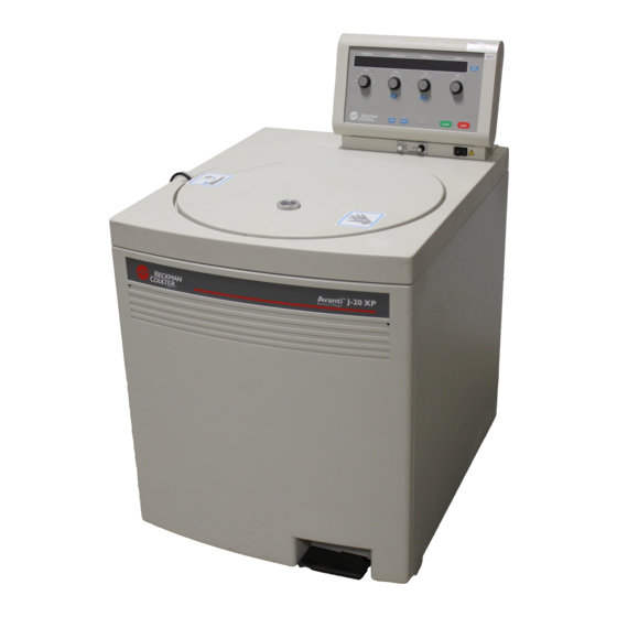
Summary of Contents for Beckman Coulter Avanti J-20 XP
- Page 1 J320XP-IM-5 Avanti J-20 XP ® Expanded-Performance Centrifuge Instruction Manual...
- Page 3 Safety During Installation and/or Maintenance This centrifuge is designed to be installed by a Beckman Coulter field service representa- tive. Installation by anyone other than authorized Beckman Coulter personnel invalidates any warranty covering the instrument.
- Page 4 Mechanical Safety For safe operation of the equipment, observe the following: • Use only the Beckman Coulter rotors and accessories designed for use in this centrifuge. • Do not exceed the maximum rated speed of the rotor in use.
- Page 5 J320XP-IM-5 May 2005 Avanti J-20 XP ® Expanded-Performance Centrifuge Instruction Manual © 2005 Beckman Coulter, Inc. Printed in the U.S.A.
-
Page 7: Table Of Contents
Contents Page INTRODUCTION Certification ..........vii Scope of this Manual . - Page 8 Contents Page SECTION 2: DESCRIPTION Centrifuge Function and Safety Features ..... . 2-1 Centrifuge Function ........2-1 Safety Features.
- Page 9 Contents Page SECTION 4: TROUBLESHOOTING Diagnostic Messages ........4-1 Accessing the Rotor in Case of Power Failure.
- Page 10 Illustrations Page Figure 1-1. Single-Phase Electrical Requirements ......1-10 Figure 1-2. Three-Phase “Y” Electrical Requirements ..... 1-10 Figure 1-3.
-
Page 11: Introduction
Introduction CERTIFICATION ® To ensure full system quality, Beckman Coulter Avanti J-20XP centrifuges are manufactured in a registered ISO 9001 facility. They have been designed and tested to be compliant (when used with Beckman Coulter rotors) with the laboratory equipment reqirements of applicable regulatory agencies. -
Page 12: Conventions
Further, the use of any equipment other than that recommended by Beckman Coulter has not been evaluated for safety. Use of any equipment not specifically recommended in this manual is the sole responsibility of the user. -
Page 13: Typographic Conventions
¤ ¤ Introduction WARNING Used whenever an action or condition may potentially cause personal injury or loss of life. Mechanical damage may also result. WARNING Indicates high voltage or risk of electric shock. Refer servicing of all areas displaying either symbol to qualified service personnel. TYPOGRAPHIC CONVENTIONS Certain typographic conventions are used throughout this manual to distinguish names of user interface components, such as keys and... -
Page 14: Canadian Regulations
Introduction CANADIAN REGULATIONS This digital apparatus does not exceed the Class A limits for radio noise emissions from digital apparatus as set out in the radio interfer- ence regulations of the Canadian Department of Communications. Le présent appareil numérique n’émet pas de bruits radioélectriques dépassant les limites applicables aux appareils numériques de Classe A prescrites dans le reglement sur le brouillage radioelectrique édicté... -
Page 15: Specifications And Preinstallation Requirements
Specifications and Preinstallation Requirements SPECIFICATIONS Only values with tolerances or limits are guaranteed data. Values without tolerances are informative data, without guarantee. CONTROL FEATURES Speed Setting range ......100 to 26 000 rpm (in 100-rpm increments below 10 000 rpm, 500-rpm increments above 10 000 rpm), or equivalent RCF (in 100 ×... -
Page 16: Operational Features
Specifications and Preinstallation Requirements OPERATIONAL FEATURES Door......6.1-cm (2.4-in.) thick structural foam with steel plate Rotor chamber diameter . -
Page 17: Available Rotors
Specifications and Preinstallation Requirements AVAILABLE ROTORS Refer to the applicable rotor manual for complete rotor descriptions. Rotor Max RCF Manual ( × g ) Rotor Profile and Description Capacity Number JA-30.50 Ti Fixed Angle, 34° (8 place) 8 × 50 mL = 108 mm 26 000 81 800... - Page 18 Specifications and Preinstallation Requirements Rotor Max RCF Manual ( × g ) Rotor Profile and Description Capacity Number JA-20 Fixed Angle, 34° (8 place) 8 × 50 mL = 108 mm 20 000 48 400 J-TB-003 JA-18.1 Fixed Angle (24 place) 24 ×...
- Page 19 Specifications and Preinstallation Requirements Rotor Manual ( × g ) Rotor Profile and Description Capacity Number JA-12 Fixed Angle, 35° (12 place) 12 × 50 mL = 144 mm 12 000 23 200 J-TB-051 JA-10 Fixed Angle, 25° (6 place) 6 ×...
- Page 20 Specifications and Preinstallation Requirements Rotor Manual ( × g ) Rotor Profile and Description Capacity Number JS-24.38 Swinging Bucket (6 place) 6 × 38.5 mL 10 000 18 000 J-TB-058 = 161 mm JS-24.15 Swinging Bucket (6 place) 6 × 15 mL 10 000 19 200 J-TB-058...
-
Page 21: Preinstallation Requirements
PREINSTALLATION REQUIREMENTS Do not attempt to install this instrument. Its purchase price includes installation by Beckman Coulter personnel. Installation by anyone other than an authorized Beckman Coulter representative invalidates any warranty covering the instrument. Preinstallation requirements have been sent prior to shipment of the instrument. -
Page 22: Electrical Requirements
Specifications and Preinstallation Requirements for power and site preparation have been met. The following equip- ment is required for preinstallation: • Voltmeter • For single phase centrifuges: two 30-ampere circuit breakers • For three phase centrifuges: three 16-ampere circuit breakers •... -
Page 23: Single And Three-Phase Power Connections
Specifications and Preinstallation Requirements WARNING To reduce the risk of electrical shock, this equipment uses a three-wire or five-wire elec- trical cord and plug to connect the centrifuge to earth-ground. To preserve this safety feature, make sure that the matching wall outlet receptacle is properly wired and earth-grounded. -
Page 24: Figure 1-1. Single-Phase Electrical Requirements
Specifications and Preinstallation Requirements 30-ampere Circuit Breaker Wall Outlet: Hubbell 9330, Bryant 96-30-FR, or Equivalent (NEMA 6-30 R) Measured Line Earth- Voltage Ground 30-ampere Circuit Breaker Figure 1-1. Single-Phase Electrical Requirements 16-ampere Circuit Breaker Measured Neutral Line Voltage Phase to Phase 16-ampere Circuit Breaker Earth- 16-ampere Circuit Breaker... -
Page 25: Connections
Specifications and Preinstallation Requirements ADDITIONAL REQUIREMENTS FOR THREE-PHASE POWER CONNECTIONS For three-phase power service to the centrifuge, use the “Y” connected configuration shown in Figure 1-3. Also note the following information: • The steady state current draw of the centrifuge can be as high as 12 amperes per phase, depending on the voltage. -
Page 26: Space And Location Requirements
Specifications and Preinstallation Requirements SPACE AND LOCATION REQUIREMENTS • Locate the instrument on a clean, level floor. • In addition to space for the centrifuge, allow a 7.7-cm (3-in.) clearance on each side of the centrifuge and a 16-cm (6.25-in.) clearance behind the instrument for air circulation. -
Page 27: Figure 1-4. Rear View And Dimensions
1.8 m 6.0 ft. Air Diverter 16.0 Depth 6.25 Air Intake Figure 1-4. Rear View and Dimensions ➠ NOTE Beckman Coulter representatives are not equipped to drill holes in your floor. The holes must be drilled before your scheduled installation. 1-13... -
Page 28: Using J2 Series Rotors In The Avanti J
(see Figure 1-5). These drive pins engage with the centrifuge spindle hub to ensure that the rotor does not slip during acceleration. Some Beckman Coulter rotors, including the JA-10, the JS-7.5, the JA-14, and the JS-13, have been manufactured without drive pins because pins were not needed when these rotors were used in J2 series centrifuges. -
Page 29: Using The Jcf-Z Continuous Flow/Zonal Rotor
Specifications and Preinstallation Requirements Rotor Drive Drive Pins Hole (Angled pins shown; pins can also be vertical or horizontal.) Drive Spindle Assembly Top View Side View Figure 1-5. Checking the Rotor for Drive Pins USING THE JCF-Z CONTINUOUS FLOW/ZONAL ROTOR Zonal Bracket Kits A special bracket and mounting hardware are required when the JCF-Z Continuous Flow/Zonal Rotor is used. - Page 30 “drag” on the bearings changes the rotor’s dynamic properties, making them similar to those of several Beckman Coulter fixed angle rotors. If rotor misidentification occurs when your JCF-Z rotor is used, first perform three runs from 0 to 5000 rpm and back to 0 rpm. If rotor misidentification recurs, replace the bearings.
- Page 31 Specifications and Preinstallation Requirements ➠ NOTE If the JCF-Z rotor is misidentified, the run speed will be limited to the maximum speed for the identified rotor. (The maximum speed for the JCF-Z rotor is 20 000 rpm.) 1-17...
-
Page 32: Description
The Avanti J-20XP is a refrigerated centrifuge that generates centrifugal forces required for a wide variety of applications. Together with the Beckman Coulter rotors designed for use in this centrifuge, applications include: • Routine processing such as sample preparations, pelleting, extractions, purifications, concentrations, phase separations,... -
Page 33: Safety Features
• An imbalance detector monitors the system during operation, causing automatic shutdown if rotor loads are severely out of balance. ® Avanti J-20XP software and firmware copyright ©2000 by Beckman Coulter, Inc., Palo Alto, CA, U.S.A. Manufactured under license from Switched Reluctance Drives Limited, Harrogate, U.K. -
Page 34: Housing And Door
Description HOUSING AND DOOR The instrument control housing is made of aluminum and molded structural foam. The door and structural-foam cover panels are finished with polyurethane enamel. The control panel is covered by a protective overlay made of coated polycarbonate. The door is opened by stepping on a foot pedal, which is located at the bottom right front of the instrument. -
Page 35: Temperature Sensing And Control
The name rating plate is affixed to the rear of the centrifuge. Check that the line voltage agrees with the voltage listed on this name rating plate before connecting the centrifuge. Always mention the serial number and the model number shown when corresponding with Beckman Coulter regarding your centrifuge. -
Page 36: Controls And Indicators
Description CONTROLS AND INDICATORS POWER SWITCH The power switch is located below the control panel (see Figure 2-1). This two-position rocker switch (I, on; O, off) controls electrical power to the centrifuge. Figure 2-1. The Power Switch CONTROL PANEL The control panel (Figure 2-2) is mounted at an angle on the centrifuge top rear for easy visibility and access. - Page 37 Used to select the rotor in use. As the knob is turned, the name of each Beckman Coulter rotor that can be run in the centrifuge appears in succession in the ROTOR ID display, and the LED by each rotor ROTOR type abbreviation (JCF: continuous flow rotors;...
- Page 38 ¤ ¤ Description SPEED Selection key is pressed to select the speed mode (RPM or RPM/RCF RCF). After the mode is selected, the SPEED knob functions as follows. • In RPM mode, each SPEED knob increment is 100 rpm at speeds up to 10 000 rpm.
- Page 39 ¤ ¤ ¤ ¤ ¤ ¤ ¤ ¤ ¤ ¤ ¤ Description TEMPERATURE Knob Used to select the rotor temperature, from –10 to +40°C. • The minimum and maximum allowable set temperatures depend TEMP °C on the set speed and the rotor in use. If a temperature is entered that cannot be achieved by the installed rotor at the set speed, the TEMP°C field will flash.
-
Page 40: Operation
Operation This section contains detailed centrifuge operating procedures. A summary is provided on page 3-2. If you are an experienced user of this centrifuge, you can turn to the summary for a quick review of operating steps. WARNING Normal operation may involve the use of solutions and test samples that are patho- genic, toxic, or radioactive. -
Page 41: Summary Of Avanti J-20Xp Run Steps
¤ ¤ ¤ ¤ ¤ Operation SUMMARY OF AVANTI J-20XP RUN STEPS For runs at temperatures other than ambient, precool or prewarm the rotor to the required temperature before the run. Press the POWER switch to on (I). Open the centrifuge door. Install the rotor. -
Page 42: Preparation And Loading
Operation PREPARATION AND LOADING For fast temperature equilibration, precool or prewarm the rotor to the required temperature before the run. Action Result 1. Turn the power switch on (I). Power is applied to the system, and the display illuminates. 2. Step on the foot pedal to The door opens. -
Page 43: Entering Run Parameters
Operation Action Result CAUTION 5. Close the centrifuge door If you leave the rotor in the centrifuge between firmly. runs, make sure the rotor is seated on the drive hub and the tie-down knob is tight before each run. (Remove the rotor from the centrifuge if you anticipate a long period between runs.) ENTERING RUN PARAMETERS SELECTING A ROTOR... - Page 44 Operation Setting RPM Action Result 1. Check to see if the red RPM RPM is the default speed mode. If the centrifuge is already in the light is lit on the display. RPM mode, skip step 2 and go on to step 3. If it is lit, go to step 3.
-
Page 45: Setting Run Time
Operation Action Result 3. Turn the SPEED knob until The centrifuge operates at a speed calculated to produce the set RCF the required RCF value value. Press to display the RPM value. RPM/RCF appears in the SPEED display. SETTING RUN TIME Pressing the key toggles the system between HR:MIN TIME/HOLD... -
Page 46: Setting Run Temperature
Operation Continuous (HOLD) Run Action Result ¤ 1. Press the The red HOLD indicator light comes on in the TIME display. TIME/HOLD to select the HOLD mode. TIME HR:MIN HOLD TIME/ HOLD 2. When all run parameters The rotor begins to accelerate and the display begins showing the •UV7TV—... -
Page 47: Setting Acceleration And Deceleration Rates
Operation Action Result Turn the TEMP °C knob until After you release the knob, the display shows the selected tempera- the required temperature appears ture. After 5 seconds, the display reverts to the actual current chamber in the display. temperature. TEMP °C TEMP °C... -
Page 48: Figure 3-1. Acceleration And Deceleration Settings Graph
Operation Table 3-2. Deceleration Settings Maximum Deceleration Slow Deceleration Full brake is used from set Reduced torque is used from set speed to No brake is used. Rotor speed to near 0 rpm, to bring 500 rpm, causing deceleration to 500 rpm to take coasts to 0 rpm. -
Page 49: Setting Up An Elutriation Run
Operation Action Result •799AH— Press the key to toggle The selected setting lights. between the MAX and SLOW acceleration settings. SLOW ACCEL Setting the Deceleration Rate Action Result •@A9AH— Press the key to toggle The selected setting lights. between the MAX, SLOW, and OFF deceleration settings. -
Page 50: Figure 3-2. Elutriation Controls
Operation DELAY ELUTRIATOR Figure 3-2. Elutriation Controls Action Result 1. Install the rotor. 2. Set up sample and buffer reservoirs and tubing lines as described in the rotor manual. Route the tubing lines through the elutriator port holes at the left side of the door seal. - Page 51 Operation Action Result •UV7TV— 5. Press The rotor accelerates to set speed. 6. When the rotor reaches set The power switch indicator lights. speed, turn on the strobe controls by pressing the Strobe strobe power switch. Power Switch DELAY ELUTRIATOR 7.
-
Page 52: Starting A Run
Operation STARTING A RUN Action Result 1. Check that all parameters are correct and the door is firmly closed. •UV7TV— 2. Press The display will start showing actual centrifuge values within •UV7TV— 5 seconds. The LED on the key flashes during acceleration. When set speed is reached, the light stays on continuously until the centrifuge begins decelerating. -
Page 53: Changing Time Settings
Operation CHANGING TIME SETTINGS • To increase or decrease the remaining run time, turn the knob to the new run time. The system will add the new remaining time to (or subtract from) the time already elapsed, and the display will show the new remaining run time. -
Page 54: Unloading The Centrifuge
Operation Action Result •UVQR— •UVQR— 1. Press to initiate The light on the key flashes until the rotor comes to a stop. deceleration. NOTE 2. After the rotor stops During runs at very cold temperatures, nomi- spinning, step on the foot nally –10°C or below, ice may form around the pedal to open the door. -
Page 55: Troubleshooting
Troubleshooting This section lists possible malfunctions, along with probable causes and corrective actions. Maintenance procedures are given in Section 5. For any problems not covered here, contact Beckman Coulter Field Service (1-800-742-2345 in the United States) for assistance. NOTE It is your responsibility to decontaminate the instrument, as well as any rotors and accesso- ries, before requesting service by Beckman Coulter Field Service. -
Page 56: Table 4-1. Diagnostic Message Chart
Table 4-1 contains information on causes and recommended actions for each diagnostic condition. If you are unable to correct the problem, call Beckman Coulter Field Service (in the United States, call 1-800-742-2345, outside of the U.S., call your local Beckman Coulter office). - Page 57 SPEED Speed control system is Rotor spinning above set Call Beckman Coulter Field malfunctioning speed; run shuts down Service. with maximum brake. DOOR Door is not latched properly or...
- Page 58 Table 4-1. Diagnostic Message Chart (continued) Diagnostic Message Problem Result Recommended Action SYS (system) There is a problem with the System shuts down Call Beckman Coulter Field system control software, EPROM, Service. or RAM •9HA7T— POWER Momentary power failure; rotor Run continues when Press...
-
Page 59: Accessing The Rotor In Case Of Power Failure
Troubleshooting ACCESSING THE ROTOR IN CASE OF POWER FAILURE WARNING Any maintenance procedure requiring removal of a panel exposes the operator to the possibility of electrical shock and/or mechanical injury. Therefore, turn the power off (O) and disconnect the instrument from the main power source, and refer such main- tenance to qualified service personnel. -
Page 60: Figure 4-1. Emergency Door Release Latch Access
Troubleshooting Figure 4-1. Emergency Door Release Latch Access Action Result 2. Insert a 4-mm or -in. The latch disengages. Allen wrench straight through one of the holes (either one) and turn the wrench to the left (counterclockwise) about one-half turn. 3. -
Page 61: Figure 4-2. Manual Door Release
Troubleshooting Manual Door Release Interlock Lever Inner Front Panel Retaining Strip Figure 4-2. Manual Door Release Action Result 5. Pull the interlock lever out Depending on the level of vacuum in the chamber at the time of the and to the left (at about a power failure, the door may or may not open. - Page 62 Troubleshooting Action Result 7. To vent the chamber vacuum, The vacuum will be completely vented several seconds after the hose grasp the red rubber hose and is detached. pull it up until it comes off of the pump fitting (see NOTE Figure 4-3).
-
Page 63: Figure 4-3. Venting The Chamber Vacuum
Troubleshooting Grasp red hose and pull up. Do not disconnect the tubing lines tied to the red hose. Vacuum Pump Red hose removed from fitting Replace red hose Figure 4-3. Venting the Chamber Vacuum... -
Page 64: Figure 4-4. Front Panel Retaining Strip
Troubleshooting To replace the panel on the centrifuge, Action Result 1. Holding the panel at the top (with the instrument label facing out), insert the three grooved brackets on the bottom inside of the door over the front panel retaining strip (see Figure 4-4). -
Page 65: Jcf-Z Rotor Identification
NOTE Misidentification can be prevented by returning your JCF-Z rotor to the Beckman Coulter factory to have magnets added to the rotor body. The magnets ensure correct rotor identification. -
Page 66: Care And Maintenance
This section describes routine care and maintenance procedures that you should perform regularly or as required. For maintenance not covered in this manual, contact Beckman Coulter Field Service. Refer to the applicable rotor manual and Rotors and Tubes for J Series Centrifuges (publication JR-IM) for instructions on the care of rotors and accessories. -
Page 67: Maintenance
Care and Maintenance MAINTENANCE Perform the following procedures regularly to ensure continued performance and long service life of the centrifuge. • Inspect the centrifuge chamber for accumulations of sample, dust, or glass particles from broken sample tubes. Clean as required (see , below). -
Page 68: Decontamination
Care and Maintenance • Clean the drive hub regularly using Solution 555 (diluted 10 to 1 with water) and a soft brush. Rinse thoroughly and dry completely. Tube Breakage If a glass tube breaks, and all the glass is not contained in the bucket or rotor, be sure to thoroughly clean the chamber. -
Page 69: Sterilization And Disinfection
IN-175 for chemical resistances of centrifuge and accessory materials. While Beckman Coulter has tested ethanol (70%) and found that it does not damage the centrifuge, no guarantee of sterility or disinfec- tion is expressed or implied. When sterilization or disinfection is a concern, consult your laboratory safety officer regarding proper... -
Page 70: Circuit Breaker And Fuses
OFF (O) position. Reset the circuit breaker by turning the power switch back to the ON (I) position. If it trips again immediately, do not reset it. Call Beckman Coulter Field Service. CAUTION Repeated attempts to reset the centrifuge circuit breaker can cause substantial damage to electrical and electronic components. -
Page 71: Supply List
For your convenience, a partial list of centrifuge supplies is given below. NOTE To receive copies of referenced publications, contact Beckman Coulter, Inc., Technical Publi- cations Department, 1050 Page Mill Road, Palo Alto, CA 94304, U.S.A., Telephone (650) 859- 1753; Fax (650) 859-1375. -
Page 72: Appendix
APPENDIX Temperature Calibration Procedure The Avanti J-20XP centrifuge specification for temperature control is ±2°C of the set temperature. That means that your sample will stay within 2°C of set temperature at all times, after rotor and system equilibration, described below. (During transient conditions, such as acceleration and deceleration, the rotor temperature may be outside this range.) The following procedure is provided for those cases in which temperature control within ±1°C is required. - Page 73 Temperature Calibration Procedure 5. After at least 1 hour, measure the temperature of the buffer or water using a thermometer or thermocouple. 6. If the measured and set temperatures are different, note how many degrees different they are and adjust the set temperature up or down that number of degrees.
- Page 74 Beckman Coulter, vice for a reasonable period of time, Beckman Coulter will or unless such repair in the sole opinion of Beckman Coulter repair or, at its election, replace such component or accessory.
- Page 75 Telephone: (27) 11-805-2014/5 Fax: (27) 11-805-4120 e-mail: beckman@intekom.co.za Beckman Coulter, Inc. • 4300 N. Harbor Boulevard, Box 3100 • Fullerton, California 92834-3100 Sales and Service: 1-800-742-2345 • Internet: www.beckmancoulter.com • Telex: 678413 • Fax: 1-800-643-4366 ©2005 Beckman Coulter, Inc. Printed on recycled paper...
Need help?
Do you have a question about the Avanti J-20 XP and is the answer not in the manual?
Questions and answers