
Related Manuals for Beckman Coulter Avanti J-15 Series


Summary of Contents for Beckman Coulter Avanti J-15 Series
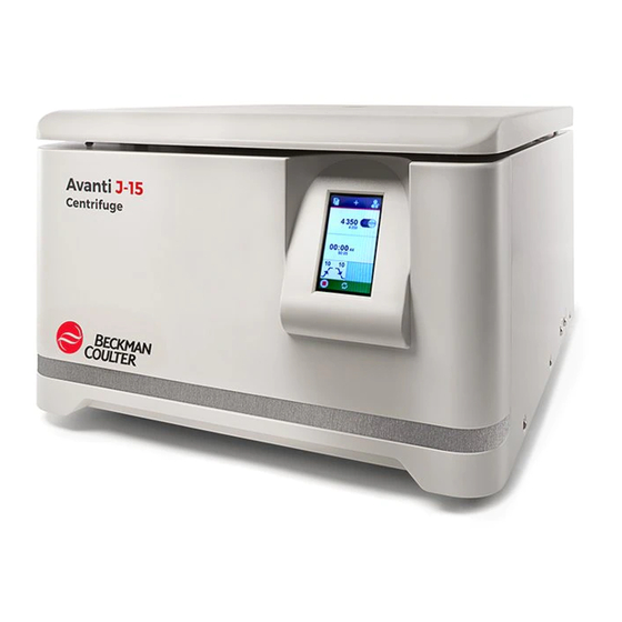
- Page 1 Instructions For Use Avanti J-15 Series Centrifuges Rx Only in the U.S.A. PN B80286AC March 2018 Beckman Coulter, Inc. 250 S. Kraemer Blvd. Brea, CA 92821 U.S.A.
- Page 2 Avanti J-15 Series Centrifuges for In Vitro Diagnostic Instructions for Use PN B80286AC (March 2018) © 2018 Beckman Coulter, Inc. All rights reserved Beckman Coulter, the stylized logo, and the Beckman Coulter product and service marks mentioned herein are trademarks or registered trademarks of Beckman Coulter, Inc.
-
Page 3: Revision History
Revision History For updates, go to techdocs.beckmancoulter.com and download the most recent manual or system help for your instrument. Initial Issue B80286AA, 05/2017 Issue AB, 09/2017 Changes or additions were made in the following: CHAPTER 1, Status Icons and Buttons; CHAPTER 1, Specifications. - Page 4 Revision History PN B80286AC...
-
Page 5: Safety Notice
Beckman Coulter, Inc. urges its customers and employees to comply with all national health and safety standards such as the use of barrier protection. This may include, but is not limited to, protective eyewear, gloves, and suitable laboratory attire when operating or maintaining this or any other automated laboratory instrumentation. -
Page 6: Instrument Safety Precautions
• Acknowledge and act upon instrument alarms and error messages. • Keep away from moving parts. • Report any broken parts to your Beckman Coulter Representative. • Open/remove and close/replace doors, covers and panels with care. • Use the proper tools when troubleshooting. -
Page 7: Safety During Installation And/Or Maintenance
Do not use the centrifuge in the vicinity of flammable liquids or vapors, and do not run such materials in the instrument. Perform only the maintenance described in the appropriate User’s Manual for the Avanti J-15 Series Centrifuges. Maintenance other than that specified in the User’s Manual should be performed only by a Beckman Coulter Representative. - Page 8 It is your responsibility to decontaminate components of the instrument before requesting service by a Beckman Coulter Representative or returning parts to Beckman Coulter for repair. Beckman Coulter will NOT accept any items which have not been decontaminated where it is appropriate to do so.
-
Page 9: Mechanical Safety
Safety Notice Safety Against Risk of Fire DANGER To reduce the risk of electrical shock, the instrument uses a three-wire electrical cord and plug to connect it to earth-ground. Make sure that the matching wall outlet receptacle is properly wired and earth-grounded. •... -
Page 10: Chemical And Biological Safety
Safety Notice Chemical and Biological Safety instrument controls, if necessary. • Never bring any flammable substances within the 30-cm (1-ft) area surrounding the centrifuge. • Never lean on the centrifuge or place items on the centrifuge while it is operating. Chemical and Biological Safety WARNING Risk of chemical injury from bleach. -
Page 11: Summary Of Instrument Labels
For Beckman Coulter products bearing this label please contact your dealer or local Beckman Coulter office for details on the take back program that will facilitate the proper collection, treatment, recovery, recycling and safe disposal of the device. -
Page 12: Multi-Compliance Label
Safety Notice Summary of Instrument Labels Multi-Compliance Label • IVD— For In Vitro Diagnostic Use. • The “RCM” (Regulatory Compliance Mark) is depicted as a triangle with a partial circle and check. The mark is applied to products that comply with the EMC requirements of the Australian Communications Media Authority (ACMA) for use in Australia and New Zealand. -
Page 13: Instrument Labels
Safety Notice Instrument Labels Instrument Labels Name Label Meaning Information Caution Symbol — Serves as a reminder that all safety instructions should be read and understood before installation, use, maintenance, and servicing are attempted. Biohazard Symbol— warns of the potential to be exposed to Biohazard biological substances that carry a significant health risk. - Page 14 Safety Notice Instrument Labels PN B80286AC...
-
Page 15: Table Of Contents
Contents Revision History, iii Safety Notice, v Alerts for Danger, Warning, Caution, and Note, v Instrument Safety Precautions, vi Cleaning, vii Safety During Installation and/or Maintenance, vii Electrical Safety, viii High Voltage, viii Safety Against Risk of Fire, ix Mechanical Safety, ix Chemical and Biological Safety, x... - Page 16 Contents Housing, 1-2 Door, 1-3 Rotor Chamber, 1-3 Temperature Sensing and Control (J-15R only), 1-3 Drive, 1-3 Controls and Indicators, 1-4 Power Switch, 1-4 Control Panel, 1-4 Digital Display, 1-5 Status Icons, 1-6 Parameter Setting Screens, 1-8 Specifications, 1-10 Available Rotors, 1-12 CHAPTER 2: Operation, 2-1...
- Page 17 Installation, A-1 Introduction, A-1 Space and Location Requirements, A-2 Securing the Centrifuge, A-4 Securing the Centrifuge to a Bench, A-4 Electrical Requirements, A-4 Test Run, A-5 Abbreviations Index Beckman Coulter, Inc. Avanti J-15 Series Centrifuge Warranty Symbols Related Documents xvii...
- Page 18 Illustrations Illustrations Avanti J-15 and J-15R Centrifuges, 1-1 Power Switch Location, 1-4 Information Page, 1-4 Control Panel, 1-5 Home Screen, 1-6 Speed (RPM) Setting Screen, 1-8 Home Screen, 2-3 Run Speed Display, 2-5 Speed Keypad, 2-5 Time Display, 2-7 Time Keypad, 2-7 Temperature Display, 2-8...
- Page 19 Tables Tables • Equipment Ratings, 1-viii Status Icons and Buttons, 1-6 Run Parameter Icons, 1-9 Specifications, 1-10 Available Rotors, 1-12 Acceleration and Deceleration Rates (in Minutes: Seconds) to and from Maximum Speed, 2-10 Diagnostics/User Messages Chart, 3-2 Troubleshooting Chart, 3-6...
- Page 20 Tables...
-
Page 21: Introduction
Intended Use For In Vitro Diagnostic Use. This Avanti J-15 Series centrifuge is intended for the separation of components through the use of relative centrifugal force. It is designed to separate human samples, including blood and other body fluids, for processing, analysis, and in vitro diagnostic testing, as well as nonhuman body samples and chemicals, including industrial and environmental samples. -
Page 22: Conventions
Further, the use of any equipment other than that recommended by Beckman Coulter has not been evaluated for safety. Use of any equipment not specifically recommended in this manual and/or the applicable rotor manual is the sole responsibility of the user. -
Page 23: System Description
CHAPTER 1 System Description Introduction This chapter provides a brief physical and functional description of the Beckman Coulter Avanti J-15 Series centrifuges. The operating controls and indicators are also described; instructions for their use are in CHAPTER 2, Operation. Chemical compatibilities of materials listed in this manual can be found in Chemical Resistances (publication IN-175). -
Page 24: Safety Features
Safety Features The Avanti J-15 series centrifuge has been designed and tested to operate safely indoors at altitudes up to 2000 m (6562 ft). Safety features include the following. • An electromechanical door lock system prevents operator contact with spinning rotors and prevents run initiation unless the door is shut and locked. -
Page 25: Door
System Description Centrifuge Chassis Door The painted aluminum and plastic door is secured to the housing by solid hinges. A window in the center allows strobe viewing. When the door is closed, the locking system engages. The door is locked when a run is in progress and can be opened only when the rotor is stopped and is selected. -
Page 26: Controls And Indicators
System Description Controls and Indicators Controls and Indicators Power Switch Figure 1.2 Power Switch Location The power switch, located on the left side of the centrifuge, controls electrical power to the centrifuge. It is also a circuit breaker that will trip to cut off power in the event of a power overload. The power switch must be turned on before the chamber door can be opened. -
Page 27: Digital Display
System Description Controls and Indicators The control panel (Figure 1.4) is mounted at an angle on the centrifuge front for easy visibility and access. It is used to enter run parameters via the touch screen, and to display run parameters, program information, and user messages. -
Page 28: Status Icons
System Description Controls and Indicators Figure 1.5 Home Screen 1. PROGRAMS — Select to see all saved programs. 2. PROGRAM NUMBER — Shows current program. If no program is selected, this is not shown. 3. ADD PROGRAM — Select to create a new program. 4. - Page 29 System Description Controls and Indicators Table 1.1 Status Icons and Buttons (Continued) SPEED The large number displays the actual value during a run. The small number displays the set value in RCF. • RPM MODE : the rotor speed is shown in revolutions per minute (RPM).
-
Page 30: Parameter Setting Screens
System Description Controls and Indicators Table 1.1 Status Icons and Buttons (Continued) START Press to start a run. STOP Press to stop a run. RUN IN PROGRESS Indicates a run is in progress. ERROR Error message includes a diagnostic code. Red background —... -
Page 31: Run Parameter Icons
System Description Controls and Indicators Table 1.2 Run Parameter Icons PLUS/MINUS (J-15R only) — In the Temperature settings, press to change the setting to a temperature above or below 0°C. ACCEPT ENTRY — Press to accept settings in Time, Temperature, Radius, Speed, RCF, and the Acceleration and Deceleration Profile. -
Page 32: Specifications
Table 1.2 Run Parameter Icons (Continued) SOUND OFF — In the Menu screen, press to turn the sounds on. SERVICE — For Beckman Coulter Service Use only. INFORMATION — In the Menu screen, press to see instrument and software information. - Page 33 System Description Specifications Table 1.3 Specifications (Continued) Specification J-15 Ventilated J-15R Refrigerated Width 55.6 cm (21.9 in.) 75.6 cm (29.8 in) Dimensions Depth 74.9 cm (29.5 in) 70.3 cm (27.7 in) Height 36.8 cm (14.5 in) 36.8 cm (14.5 in) Weight Weight, not including rotor 93 kg (205 lbs)
-
Page 34: Available Rotors
System Description Available Rotors Available Rotors The following Beckman Coulter rotors can be used in the Avanti J-15 and J-15R centrifuges. The rotors are described in individual manuals that accompany each rotor. Table 1.4 Available Rotors Max RCF ( g) -
Page 35: Chapter 2: Operation
CHAPTER 2 Operation Introduction This section contains centrifuge operating procedures. A summary is provided at the start of this section. If you are an experienced user of this centrifuge, you can turn to the summary for a quick review of operating steps. -
Page 36: Installing The Rotor
Operation Installing the Rotor Installing the Rotor Prepare the rotor for centrifugation as described in the applicable rotor manual (refer to JA-10.100 Fixed-Angle Rotor Instructions For Use (B80290) or JS-4.750 Swinging-Bucket Rotor Instructions For Use (B80289)). NOTE For runs at temperatures cooler than ambient room temperature, refrigerate the rotor beforehand for fast equilibration. -
Page 37: Manual Run
Operation Manual Run Manual Run When a run-parameter key ( ) is selected, a SPEED, TIME, TEMPERATURE, ACCEL DECEL, RADIUS parameter can be entered or changed. Figure 2.1 Home Screen 1. PROGRAMS — Select to see all saved programs (see Programmed Run). -
Page 38: Speed
J-15R Refrigerated Centrifuge: — When using multiwell-plate carriers on the JS-4.750 rotor, limit rotor speed to 4450 RPM when running up to three stacked Beckman Coulter plates separated by cap strips. Reduce speed to 2700 RPM if running four stacked plates. —... -
Page 39: Run Speed Display
Operation Manual Run To Set the Run Speed: Select to toggle between the modes (Figure 2.2). Select the display (Figure 2.2). The setting screen opens. SPEED Run Speed Figure 2.2 Run Speed Display Use the keypad (Figure 2.3) to enter the desired Run Speed or RCF. NOTE The display will always include a zero. -
Page 40: Radius
Operation Manual Run Radius setting is only applicable when the is set to . Enter a Radius Speed RCF Mode radius within the minimum and maximum radius of the rotor and accessories in use. See JS-4.750 Swinging-Bucket Rotor Instructions For Use (B80289) or JA-10.100 Fixed-Angle Rotor Instructions For Use (B80290) for RCF and Radius settings. -
Page 41: Time Display
Operation Manual Run Select the display (Figure 2.4). The setting screen opens. TIME Time Figure 2.4 Time Display a. Use the keypad to enter the run time (Figure 2.5). Figure 2.5 Time Keypad 1. CANCEL, return to Home screen 2. Allowable time range 3. -
Page 42: Temperature (J-15R Only)
Operation Manual Run Temperature (J-15R only) setting can be set to cool the chamber to a desired temperature. Run temperature Temperature can be set from –10 to +40°C. If no value is entered, the centrifuge selects the last entered temperature. To pre-cool the rotor chamber, run a 30 minute cycle at the required temperature using an empty rotor, and the speed set at 2000 rpm. -
Page 43: Acceleration/Deceleration
Operation Manual Run a. To enter a temperature below 0°C, select b. Select to accept the temperature setting. If the entered temperature ACCEPT ENTRY is outside the valid temperature range, the button is disabled. Enter a valid Accept Entry temperature. OR select . -
Page 44: Start
Operation Manual Run Use the up and down arrows to enter the selected acceleration and deceleration rate numbers. The red lines change their slope to indicate the setting. See (Table 2.1) for the Acceleration and Deceleration rates. • Acceleration settings: ) through Slow Maximum... -
Page 45: Pulse Function
Operation Programmed Run Pulse Function NOTE The Time and Accel/Decel settings are overridden by the Pulse function. function eliminates the need to press the keys for short duration runs. Pulse START STOP Press and hold the key. The rotor accelerates at maximum rate to the set speed and START continues to spin as long as the key remains pressed. - Page 46 Operation Programmed Run Press to open the chamber door. OPEN DOOR Install the rotor according to the applicable rotor manual (refer to JA-10.100 Fixed-Angle Rotor Instructions For Use (B80290) or JS-4.750 Swinging-Bucket Rotor Instructions For Use (B80289)). NOTE Before installing the rotor, ensure the drive hub is sufficiently lubricated. See CHAPTER 4, Care and Maintenance for instructions.
-
Page 47: Create A New Program
Operation Programmed Run Create a New Program On the screen, select . The program settings screen opens Home NEW PROGRAM (Figure 2.10) with the current run settings. Figure 2.10 Program Settings Screen 1. CANCEL — return to Home screen 2. Program Number 3. -
Page 48: Use An Existing Program
Operation Programmed Run The program can be protected to prevent it from being changed or deleted. When Security added to a program, a four digit security PIN number (see Setting a Security PIN Number) or the administrator PIN number (see CHAPTER 3, Troubleshooting Chart) must be entered before changing or deleting the program. -
Page 49: Edit An Existing Program
Operation Programmed Run When the rotor stops, a tone sounds. Select to open the chamber door; lift the OPEN DOOR door to access the rotor. Edit an Existing Program Existing programs can be edited. NOTE If the program is secured by a PIN number, the correct PIN number (see Setting a Security PIN Number) or the administrator PIN number (see... -
Page 50: Delete A Program
Operation Programmed Run Select the setting to be edited. Procedures for entering settings for programs are the same as those described in Manual Run. Enter run parameters ( SPEED TIME TEMPERATURE ACCEL/DECEL b. Select after each setting has been entered. ACCEPT ENTRY NOTE If an unacceptable parameter value is entered, ACCEPT ENTRY... -
Page 51: Delete Program Confirmation Screen
Operation Programmed Run A confirmation screen appears (Figure 2.12). Select to delete the program. DELETE OR select to return to the previous screen. CANCEL Figure 2.12 Delete Program Confirmation Screen Select the shaded area in the program library screen to return to the screen. -
Page 52: Setting A Security Pin Number
Operation Programmed Run Setting a Security PIN Number A security PIN number can be added to a program to prevent it from being edited or deleted. To Add a Security PIN Number: Select . The screen opens (Figure 2.13). The SECURITY Security Pin Entry Security Pin Entry... -
Page 53: Menu Screen
Operation Menu Screen Menu Screen Figure 2.14 Menu Screen 1. Shaded area- Select anywhere in this area to return to the Home screen 2. DIAGNOSTIC HISTORY 3. SPEAKER ON/OFF 4. SERVICE 5. INFORMATION Diagnostic Messages When an error occurs, an error message appears on the screen (Figure 2.15). -
Page 54: Diagnostic Messages
Operation Menu Screen Figure 2.15 Diagnostic Messages 1. Diagnostic Messages Select the error message on the page to bring up the (Figure 2.16) which allows Home diagnostics list the user to acknowledge the diagnostic. Figure 2.16 Diagnostics List 1. Select to close the diagnostics list 2. -
Page 55: Diagnostic History
Operation Menu Screen To view a list of the most recent diagnostic codes, select . The MENU > DIAGNOSTICS opens (Figure 2.17). Diagnostic History Figure 2.17 Diagnostic History 1. Shaded Area — Select anywhere in this area to return to the Menu screen. 2. -
Page 56: Disable/Enable The Audible Tones
Operation Menu Screen Figure 2.18 Diagnostics Screen — Settings and Conditions 1. Run Settings 2. Run Conditions Two tabs provide specific information about the state of the instrument at the time of the error (Figure 2.18). • Select to see the settings at the time of the error. RUN SETTINGS •... -
Page 57: Service
To disable audible tones, select . The icon changes to SOUND ON SOUND OFF Or, to enable audible tones, press the . The icon changes to SOUND OFF SOUND ON Service This is for Beckman Coulter Service personnel only. Information 2-23 PN B80286AC... -
Page 58: Information Screen
Operation Menu Screen Select the Information icon to see an information screen with the instrument information (Figure 2.19). Figure 2.19 Information Screen 1. Centrifuge 2. Software Version 3. Total Runtime in hours: minutes 4. Total Number of Runs 2-24 PN B80286AC... -
Page 59: Chapter 3: Troubleshooting
NOTE It is your responsibility to decontaminate the instrument, as well as any rotors and/or accessories, before requesting service by Beckman Coulter Field Service. Diagnostics/User Messages Chart Refer to Table 3.1 to determine the nature of the condition and any recommended actions. If a... -
Page 60: Diagnostics/User Messages Chart
Troubleshooting Diagnostics/User Messages Chart Table 3.1 Diagnostics/User Messages Chart Message Definition/Result Recommended Action A200 - Power Supply • Confirm that AC power cord is AC power loss during run, rotor stopped. connected securely. • Confirm that AC line voltage and frequency are within normal operating range. - Page 61 Troubleshooting Diagnostics/User Messages Chart Table 3.1 Diagnostics/User Messages Chart (Continued) Message Definition/Result Recommended Action D115 - Control Software Error Contact us Rotor coasts to a stop. Door remains locked for 45 minutes. D121 - Control Software Error Contact us Rotor coasts to a stop. Door remains locked for 45 minutes.
- Page 62 Troubleshooting Diagnostics/User Messages Chart Table 3.1 Diagnostics/User Messages Chart (Continued) Message Definition/Result Recommended Action D307 - Drive Rotor ID Contact us Rotor brakes to a stop per profile. D308 - Drive Unrecognized Rotor Contact us Rotor brakes to a stop per profile.
-
Page 63: Other Possible Problems
Troubleshooting Other Possible Problems Table 3.1 Diagnostics/User Messages Chart (Continued) Message Definition/Result Recommended Action D605 - Drive Drive Performance Contact us Rotor coasts to a stop. D606 - Drive Drive Performance • Confirm the rotor is tied down. • If the problem persists, contact Rotor coasts to a stop. -
Page 64: Troubleshooting Chart
Troubleshooting Other Possible Problems Table 3.2 Troubleshooting Chart Problem Problem/Result Recommended Action Rotor cannot achieve Electrical failure Make sure the power cord is securely connected; set speed contact Motor failure Contact Door will not open Rotor spinning Wait until the rotor stops. Power not on Plug in the power cord;... -
Page 65: Retrieving Your Sample In Case Of A Power Failure
Troubleshooting Retrieving Your Sample in Case of a Power Failure Retrieving Your Sample in Case of a Power Failure WARNING Risk of personal injury. Never attempt to override the door interlock system while the rotor is spinning. Wait for the rotor to come to a complete stop before attempting to open the door. - Page 66 Troubleshooting Retrieving Your Sample in Case of a Power Failure Pull on the cords, or insert a screwdriver through the two cords, and pull to release the latch and open the door. WARNING Risk of personal injury. If the door is open and the rotor is still spinning, close the door and wait until it stops before attempting to access it.
-
Page 67: Care And Maintenance
Troubleshooting. NOTE It is your responsibility to decontaminate the centrifuge, as well as any rotors and/or accessories, before requesting service by Beckman Coulter Field Service. Instrument Care WARNING Risk of personal injury. Any maintenance procedure requiring removal of a panel exposes the operator to the possibility of electrical shock and/or mechanical injury. -
Page 68: Cleaning
Care and Maintenance Instrument Care Cleaning WARNING Risk of personal injury or contamination. Prior to cleaning equipment that has been exposed to hazardous material, contact the appropriate chemical and biological safety personnel. Always use the appropriate Personal Protective Equipment (PPE) when cleaning the centrifuge. WARNING Risk of personal injury. -
Page 69: Tube Breakage
Care and Maintenance Instrument Care Remove the rotor from the centrifuge and clean the drive shaft, shaft cavity, threads, and the tie-down screw regularly using a mild detergent such as Solution 555 and a soft brush. a. Dilute the detergent with water (10 parts water to 1 part detergent). b. -
Page 70: Sterilization And Disinfection
Do not use Ethanol or other combustible materials near operating centrifuges. While Beckman Coulter has tested ethanol (70%) and found that it does not damage the centrifuge, no guarantee of sterility or disinfection is expressed or implied. When sterilization or disinfection is a concern, consult your laboratory safety officer regarding proper methods to use. -
Page 71: Supply List
Replacement Parts Description Part Number Anchor Kit C01992 Supplies NOTE For SDS information, go to the Beckman Coulter website at www.beckmancoulter.com. Description Part Number Silicone vacuum grease (1 oz) 335148 Solution 555 (1 qt) 339555 Program library record... - Page 72 Care and Maintenance Supply List PN B80286AC...
-
Page 73: Appendix A: Installation
APPENDIX A Installation Introduction WARNING Risk of personal injury or equipment damage. The J-15 centrifuge weighs 93 kg (205 lb). the J-15R centrifuge weighs 120 kg (265 lb). Do not attempt to lift or move it without assistance. Follow your safety officer’s instructions regarding lifting heavy objects. -
Page 74: Space And Location Requirements
Installation Space and Location Requirements Space and Location Requirements WARNING Risk of personal injury or equipment damage. Vapors from flammable reagents or combustible fluids could enter the centrifuge air system and be ignited by the motor. Do not place the centrifuge near areas containing flammable reagents or combustible fluids. -
Page 75: Avanti J-15 Centrifuge Dimensions (Cm/In
Installation Space and Location Requirements Figure A.2 Avanti J-15 Centrifuge Dimensions (cm/in) Figure A.3 Avanti J-15R Centrifuge Dimensions (cm/in) PN B80286AC... -
Page 76: Securing The Centrifuge
Securing the Centrifuge Securing the Centrifuge to a Bench Avanti J-15 series centrifuges are certified to meet the requirements of the European CE mark. To meet these requirements, the centrifuge can be secured to the bench using the optional anti-rotation kit (PN C01992). This will prevent the centrifuge from moving in the unlikely event of a rotor mishap. -
Page 77: Test Run
Installation Test Run Test Run NOTE The centrifuge must be plugged in and the power switch turned to the on position (I) before the door can be opened. We recommend that you make a test run to ensure that the centrifuge is in proper operating condition following shipment. - Page 78 Installation Test Run PN B80286AC...
-
Page 79: Abbreviations
Abbreviations PN — Part number A — Ampere RCF — Relative centrifugal field Btu — British thermal unit Rmax — Maximum radius bps — Bits per second RPM — Rotations per minute °C — Degrees Celsius or Degrees Centigrade SDS — Safety data sheets CE —... - Page 80 Abbreviations Abbreviations-2 PN B80286AC...
-
Page 81: Index
2-10 electrical requirements, set, error message, 1-8, 2-19 anti-rotation kit, audible tones enable and disable, 2-22 Help, Beckman Coulter Customer Support, housing, Beckman Coulter Customer Support Center, contacting, imbalance, installation rotor, call center, contact information, installation, centrifuge, capacity, 1-12... - Page 82 Spinkote, 4-1, start, 2-10 defined, Abbreviations-1 sterilization, RCF-Relative Centrifugal Field storage, description, 1-12 supplies, release cords, manual door latch override, support, Beckman Coulter customer, replacement parts, rotor chamber, installation, temperature rotors, 1-12 set, Temperature Sensing and Control, defined, Abbreviations-1 time...
- Page 83 Index defined, Abbreviations-1 WEEE defined, Abbreviations-1 Index-3...
- Page 84 Index Index-4...
-
Page 85: Beckman Coulter, Inc
(1) year after delivery of an Avanti J-15 Series centrifuge (the product), to the original buyer by Beckman Coulter or by an authorized representative, provided that investigation and factory inspection by Beckman Coulter discloses that such defect developed under normal and proper use. - Page 86 Beckman Coulter, Inc. Avanti J-15 Series Centrifuge Warranty Warranty-2 PN B80286AC...
-
Page 87: Symbols
Symbols English / Deutsch / Español / Français / Italiano / Portugués / Русский / 中文 / 日本語 / 한국어 Symbol Simbole Symbol символ Simbolo Title / Titel / Titulo / Titre / Titolo / Titulo / Название / 标题 / タイトル / 제목 Symbole Simbolo 상징... - Page 88 Symbols English / Deutsch / Español / Français / Italiano / Portugués / Русский / 中文 / 日本語 / 한국어 Symbol Simbole Symbol символ Simbolo Title / Titel / Titulo / Titre / Titolo / Titulo / Название / 标题 / タイトル / 제목 Symbole Simbolo 상징...
-
Page 90: Related Documents
Use PN B80289 JA-10.100 Fixed-Angle Rotor Instructions for PN B80290 Instructions for Using the Anti-Rotation Anchoring Kit to Secure the Avanti J-15 Series Benchtop Centrifuges PN B80291 JS-4.750 Swinging-Bucket Rotor and JA-10.100 Fixed Angle Rotor Safety Manual PN C01058...
Need help?
Do you have a question about the Avanti J-15 Series and is the answer not in the manual?
Questions and answers