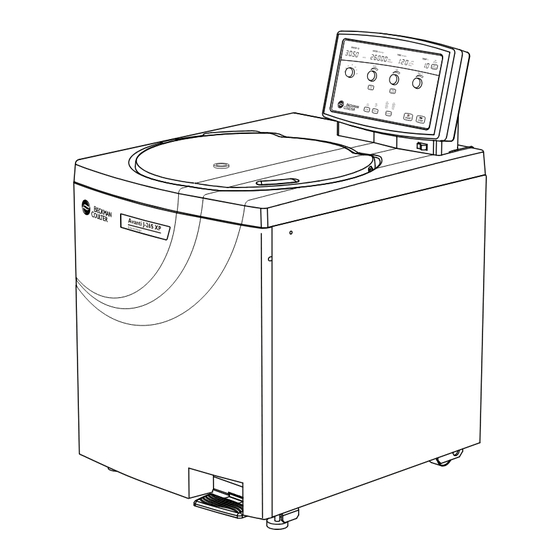
Beckman Coulter Avanti J-26S XP Instructions For Use Manual
High-performance centrifuge
Hide thumbs
Also See for Avanti J-26S XP:
- Instructions for use manual (36 pages) ,
- Instructions for use manual (158 pages)

Related Manuals for Beckman Coulter Avanti J-26S XP


Summary of Contents for Beckman Coulter Avanti J-26S XP
- Page 1 Instructions For Use Avanti J-26S XP High-Performance Centrifuge PN B10087AB June 2012 Beckman Coulter, Inc. 250 S. Kraemer Blvd. Brea, CA 92821...
- Page 2 Beckman Coulter, Inc. Beckman Coulter, the stylized logo, and Avanti are trademarks of Beckman Coulter, Inc. and are registered in the USPTO. All other trademarks, service marks, products, or services are trademarks or registered trademarks of their respective holders.
- Page 3 This instrument is designed to be installed by a Beckman Coulter Field Service representative. Installation by anyone other than authorized Beckman Coulter personnel invalidates any warranty covering the instrument. Also, if the instrument needs to be moved, a Beckman Coulter Field Service representative must reinstall and relevel the instrument in its new location.
- Page 4 Mechanical Safety For safe operation of the equipment, observe the following: • Use only the Beckman Coulter rotors and accessories designed for use in this instrument. • Do not exceed the maximum rated speed of the rotor in use. • NEVER attempt to slow or stop a rotor by hand.
- Page 5 • Dispose of all waste solutions according to appropriate environmental health and safety guidelines. It is your responsibility to decontaminate the instrument and accessories before requesting service by Beckman Coulter Field Service. PN B10087AB...
- Page 6 Safety Notice Chemical and Biological Safety PN B10087AB...
-
Page 7: Table Of Contents
Contents Safety Notice, iii Alerts for Danger, Warning, Caution, Important, and Note, iii Safety During Installation and/or Maintenance, iii Electrical Safety, iv Safety Against Risk of Fire, iv Mechanical Safety, iv Chemical and Biological Safety, v Introduction, xiii Certification, xiii Scope of Manual, xiii Conventions, xiv... - Page 8 Features, 1-7 Operational Features, 1-8 Physical Data, 1-9 Available Rotors, 1-10 CHAPTER 2: Operation, 2-1 Introduction, 2-1 Summary of Avanti J-26S XP Run Procedures, 2-2 Section and Loading, 2-3 Entering Run Parameters, 2-4 Selecting a Rotor, 2-4 Setting Run Speed, 2-4...
- Page 9 Using J2 Series Rotors in the Avanti J-26S XP, A-6 Checking for Rotor Drive Pins, A-6 Using the JA-18 Rotor, A-7 Using the JCF-Z Continuous Flow/Zonal Rotor, A-8 APPENDIX B: Temperature Calibration Procedure, B-1 Introduction, B-1 Beckman Coulter, Inc. Avanti J Series Centrifuge Warranty Related Documents...
- Page 11 Illustrations Illustrations The Power Switch, 1-4 The Control Panel, 1-4 Acceleration and Deceleration Settings Graph, 2-8 Elutriation Controls, 2-9 Emergency Door Release Latch Access, 3-5 Manual Door Release, 3-6 Venting the Chamber Vacuum, 3-8 Front Panel Retaining Strip, 3-9 Single-Phase Electrical Requirements, A-3 Three-Phase “Y”...
- Page 12 Tables Tables Acceleration Settings, 2-7 Deceleration Settings, 2-8 Diagnostic Message Chart, 3-2 Nominal Supply Voltage Ratings for the Avanti J-26S XP, A-2 Required Wire Connections, A-3...
-
Page 13: Safety Notice
Scope of Manual This manual is designed to familiarize centrifuge users and site engineers with the Avanti J-26S XP centrifuge, its functions, specifications, operation, and routine care and maintenance. Beckman Coulter recommends that you read this entire manual, especially the... -
Page 14: Conventions
For Beckman Coulter products bearing this label please contact your dealer or local Beckman Coulter office for details on the take back program that will facilitate the proper collection, treatment, recovery, recycling and safe disposal of the device. -
Page 15: Description
Centrifuge Function and Safety Features Centrifuge Function The Avanti J-26S XP is a refrigerated centrifuge that generates centrifugal forces required for a wide variety of applications. Together with the Beckman Coulter rotors designed for use in this centrifuge, applications include: •... -
Page 16: Safety Features
Safety Features Avanti J-26S XP centrifuges have been designed and tested to operate safely indoors at altitudes up to 2000 m (6562 ft). Safety features include the following. -
Page 17: Drive
The name rating plate is affixed to the rear of the centrifuge. Check that the line voltage agrees with the voltage listed on this name rating plate before connecting the centrifuge. Always mention the serial number and the model number shown when corresponding with Beckman Coulter regarding your centrifuge. -
Page 18: Controls And Indicators
Description Controls and Indicators Controls and Indicators Power Switch The power switch is located below the control panel (see Figure 1.1). This two-position rocker switch ( , on; , off) controls electrical power to the centrifuge. Figure 1.1 The Power Switch Control Panel The control panel (Figure... - Page 19 ROTOR Knob Used to select the rotor in use. As the knob is turned, the name of each Beckman Coulter rotor that can be run in the centrifuge appears in succession in ROTOR the ROTOR ID display, and the LED by each rotor type abbreviation (JCF: continuous flow rotors;...
- Page 20 Description Controls and Indicators TIME Selection Two time modes are available. The HR:MIN mode is used for runs of specified lengths. The HOLD mode is used for continuous runs of unspecified lengths. The HOLD key is used to toggle between the two modes. In HR:MIN mode: •...
-
Page 21: Specifications
Description Specifications System Keys START Pressed to begin a run. When START is pressed, the display immediately shows the actual centrifuge values. The green START light flashes during acceleration until set speed is reached, and then remains on continuously until deceleration begins. STOP Pressed to end a run;... -
Page 22: Operational Features
Description Specifications Specifications Description Temperature • Setting range: — –10 to +40°C (in 1°C increments) • Accuracy: — rotor temperature controlled to within 2°C of set temperature (after equilibration) • Ambient temperature range: — 16 to 38°C (60 to 100°F) •... -
Page 23: Physical Data
Description Specifications Physical Data Specification Description Width 71 cm (28 in.) Depth • 86 cm (34 in.) • including air diverter extending from back panel — 102 cm (40.25 in.) Height • with door closed — 86 cm (34 in.) •... -
Page 24: Available Rotors
Description Available Rotors Available Rotors Refer to the applicable rotor manual for complete rotor descriptions. Rotor Rotor Manual Rotor Profile Description Code ( g) Max Capacity Number 30.50 26,000 81,800 8 50 mL J-TB-070 JA-30.50 Ti Fixed Angle, 34° (8 place) = 108 mm JA-25.50 Ti... - Page 25 Description Available Rotors Rotor Rotor Manual Rotor Profile Description Code ( g) Max Capacity Number JA-18.1 18.1 J-TB-037 Fixed Angle (24 place) 45° adapter 18,000 42,100 24 1.8 mL = 116 mm 17,000 36,300 24 1.8 mL 25° adapter = 112 mm JA-18 18,000...
- Page 26 Description Available Rotors Rotor Rotor Manual Rotor Profile Description Code ( g) Max Capacity Number JA-10 10,000 17,700 6 500 mL J-TB-006 Fixed Angle, 25° (6 place) = 158 mm JLA-10.500 10.500 10,000 18,600 6 500 mL J-TB-048 Fixed Angle, 20°...
- Page 27 Temperature performance for the JA-30.50 Ti rotor in the Avanti J-26S XP is as follows: 15°C minimum at 26,000 RPM (at 30°C ambient); 4°C minimum at 21,500 RPM (30°C ambient). c. Maximum speed for the JA-30.50 Ti rotor is 26,000 RPM in the Avanti J-26S XP centrifuge, and 30,000 RPM in the Avanti J-30I centrifuge.
- Page 28 Description Available Rotors 1-14 PN B10087AB...
-
Page 29: Chapter 2: Operation
CHAPTER 2 Operation Introduction This section contains detailed centrifuge operating procedures. A summary is provided on page 2-2. If you are an experienced user of this centrifuge, you can turn to the summary for a quick review of operating steps. WARNING Normal operation may involve the use of solutions and test samples that are pathogenic, toxic, or radioactive. -
Page 30: Summary Of Avanti J-26S Xp Run Procedures
Operation Summary of Avanti J-26S XP Run Procedures Summary of Avanti J-26S XP Run Procedures For runs at temperatures other than ambient, precool or prewarm the rotor to the required temperature before the run. Press the switch to on ( POWER Open the centrifuge door. -
Page 31: Section And Loading
Operation Section and Loading Section and Loading For fast temperature equilibration, precool or prewarm the rotor to the required temperature before the run. Turn the power switch on ( Power is applied to the system, and the display illuminates. Step on the foot pedal to open the door. The door opens. -
Page 32: Entering Run Parameters
Operation Entering Run Parameters Entering Run Parameters Selecting a Rotor Turn the knob until the rotor in use appears in the display. ROTOR Small green LEDs by each rotor type abbreviation light one at a time, and the rotors of that type appear consecutively in the display. -
Page 33: Setting Run Time
Operation Entering Run Parameters Turn the knob until the required RPM appears in the display. SPEED SPEED When the run is started, the centrifuge operates at the set speed. The corresponding RCF is automatically calculated. a. Press to display the RCF value. RPM/RCF Setting RCF Check to see if the red... - Page 34 Operation Entering Run Parameters Timed Run Turn the knob until the required run time appears in the display. TIME TIME If you enter more than 59 minutes in the minutes field, the system automatically converts the entry to hours and minutes after is pressed.
-
Page 35: Setting Run Temperature
Operation Entering Run Parameters Setting Run Temperature Select a run temperature between –10 and +40°C, in 1°C increments. NOTE For runs at temperatures other than ambient, always refrigerate or warm the rotor to the required run temperature before the run. For low-temperature runs, precool the system by running a precooled rotor at 2000 RPM at the required temperature for at least 30 minutes. -
Page 36: Acceleration And Deceleration Settings Graph
Operation Entering Run Parameters Table 2.2 Deceleration Settings Maximum Deceleration Slow Deceleration Full brake is used from set Reduced torque is used from set speed to No brake is used. Rotor speed to near 0 RPM, to 500 RPM, causing deceleration to 500 RPM to coasts to 0 RPM. -
Page 37: Setting Up An Elutriation Run
Operation Entering Run Parameters Press the key to toggle between the acceleration settings. ACCEL SLOW The selected setting lights. SLOW ACCEL Setting the Deceleration Rate Press the key to toggle between the , and deceleration settings. DECEL SLOW The selected setting lights. SLOW DECEL Setting Up an Elutriation Run... - Page 38 Operation Entering Run Parameters Install the rotor. Set up sample and buffer reservoirs and tubing lines as described in the rotor manual. Route the tubing lines through the elutriator port holes at the left side of the door seal. b. Close the centrifuge door. Turn the knob to the position.
-
Page 39: Starting A Run
Operation Changing Parameters During a Run When the rotor speed has stabilized, look through the port in the centrifuge door and turn the knob until the elutriation chamber in the rotor is synchronized with the strobe. DELAY • (The chamber will appear to be motionless.) •... -
Page 40: Changing Time Settings
Operation Stopping a Run Changing Time Settings To increase or decrease the remaining run time, turn the knob to the new run time. • The system will add the new remaining time to (or subtract from) the time already elapsed, and the display will show the new remaining run time. -
Page 41: Unloading The Centrifuge
Operation Unloading the Centrifuge After the rotor stops spinning, step on the foot pedal located on the front of the centrifuge, to open the door. NOTE During runs at very cold temperatures, nominally –10°C or below, ice may form around the door opening, causing the door to stick shut. - Page 42 Operation Unloading the Centrifuge 2-14 PN B10087AB...
-
Page 43: Chapter 3: Troubleshooting
CHAPTER 4, Care and Maintenance. For any problems not covered here, contact Beckman Coulter Field Service (1-800-742-2345 in the United States; outside the U.S. contact your local Beckman Coulter office or visit us at www.beckmancoulter.com) for assistance. NOTE It is your responsibility to decontaminate the instrument, as well as any rotors and/or accessories, before requesting service by Beckman Coulter Field Service. -
Page 44: Diagnostic Message Chart
If you are unable to correct the problem, call Beckman Coulter Field Service (in the United States, call 1-800-742-2345; outside of the U.S., call your local Beckman Coulter office or visit us at www.beckmancoulter.com). - Page 45 SPEED Speed control system is Rotor spinning above set Call Beckman Coulter Field malfunctioning speed; run shuts down Service. with maximum brake DOOR Door is not latched properly DOOR LED lights after Open the door and close it firmly;...
- Page 46 Keep the door closed as much as possible. a. In the United States, call 1-800-742-2345. Outside the U.S., contact your local Beckman Coulter office or visit us at www.beckmancoulter.com. PN B10087AB...
-
Page 47: Accessing The Rotor In Case Of Power Failure
Troubleshooting Accessing the Rotor in Case of Power Failure Accessing the Rotor in Case of Power Failure WARNING Any maintenance procedure requiring removal of a panel exposes the operator to the possibility of electrical shock and/or mechanical injury. Therefore, turn the power off ( ) and disconnect the instrument from the main power source by removing the Mains (power) plug from the outlet receptacle, and refer such... -
Page 48: Manual Door Release
Troubleshooting Accessing the Rotor in Case of Power Failure Turn the power switch to off ( ) and unplug the power cord from the main source by removing the Mains (power) plug from the outlet receptacle. • The Mains (power) plug is the disconnect device and must remain easily accessible. —... - Page 49 Troubleshooting Accessing the Rotor in Case of Power Failure Pull the interlock lever out and to the left (at about a 45-degree angle), and while holding it out, step on the foot pedal. Depending on the level of vacuum in the chamber at the time of the power failure, the door may or may not open.
-
Page 50: Venting The Chamber Vacuum
Troubleshooting Accessing the Rotor in Case of Power Failure Figure 3.3 Venting the Chamber Vacuum 1. Step 1 5. Grasp red hose and pull up Do not disconnect the tubing lines tied to the red hose. 2. Step 2 6. Red hose removed from fitting 3. -
Page 51: Front Panel Retaining Strip
Troubleshooting Accessing the Rotor in Case of Power Failure To replace the panel on the centrifuge, Holding the panel at the top (with the instrument label facing out), insert the three grooved brackets on the bottom inside of the door over the front panel retaining strip (see Figure 3.4). -
Page 52: Jcf-Z Rotor Identification
If the JCF-Z rotor is misidentified, the run speed will be limited to the maximum speed for the identified rotor. (The maximum speed for the JCF-Z rotor is 20,000 RPM.) * In the United States, call 1-800-742-2345. Outside the U.S., contact your local Beckman Coulter office or visit us at www.beckmancoulter.com. -
Page 53: Chapter 4: Care And Maintenance
Inspect the centrifuge chamber for accumulations of sample, dust, or glass particles from broken sample tubes. a. Clean as required (see Cleaning below). * In the United States, call 1-800-742-2345. Outside the U.S., contact your local Beckman Coulter office or visit us at www.beckmancoulter.com. PN B10087AB... -
Page 54: Cleaning
Care and Maintenance Maintenance Check the air filter on the back panel for obstructions. a. Keep vents clear and clean. Wipe condensation out of the chamber between runs with a sponge or clean cloth to prevent chamber icing. If chamber icing occurs, defrost the system and wipe moisture out of the chamber before use. a. -
Page 55: Decontamination
Ethanol is a flammability hazard. Do not use it in or near operating centrifuges. While Beckman Coulter has tested ethanol (70%) and found that it does not damage the centrifuge, no guarantee of sterility or disinfection is expressed or implied. When sterilization or disinfection is a concern, consult your laboratory safety officer regarding proper methods to use. -
Page 56: Replacing The Air Filter
Then set the bottom edge down. Circuit Breaker and Fuses There are no user-replaceable fuses in the Avanti J-26S XP centrifuge. If the centrifuge circuit breaker trips for any reason, the power switch will move to the OFF ( position. -
Page 57: Storage And Transport
Failure to attach this notification will result in return or disposal of the items without review of the reported problem. * In the United States, call 1-800-742-2345. Outside the U.S., contact your local Beckman Coulter office or visit us at www.beckmancoulter.com. -
Page 58: Supply List
Tubing Adapter, stainless steel, for size 15 tubing (qty 2) 363831 Cable Clamp, nylon, 9.6-mm ( /8-in.) I.D. (qty 10) 000596 Elutriation upgrade kit 366562 * In the United States, call 1-800-742-2345. Outside the U.S., contact your local Beckman Coulter office or visit us at www.beckmancoulter.com. PN B10087AB... -
Page 59: Appendix A: Preinstallation Requirements
APPENDIX A Preinstallation Requirements Preinstallation Requirements Do not attempt to install this instrument. Its purchase price includes installation by Beckman Coulter personnel. Installation by anyone other than an authorized Beckman Coulter representative invalidates any warranty covering the instrument. Preinstallation requirements have been sent prior to shipment of the instrument. The following information is provided in case the centrifuge must be relocated. -
Page 60: Nominal Supply Voltage Ratings For The Avanti J-26S Xp
Preinstallation Requirements Preinstallation Requirements Table A.1 Nominal Supply Voltage Ratings for the Avanti J-26S XP Instrument Part Nominal Instrument Number Nominal Instrument Part (Elutriation Supply Power Cord and Plug Voltage Rating Number System) Frequency Description Single-phase, B14535 B14541 180–264 V,... -
Page 61: Single-Phase Electrical Requirements
Preinstallation Requirements Preinstallation Requirements Figure A.1 Single-Phase Electrical Requirements 1. 30-ampere Circuit Breaker 3. Earth-Ground 2. Wall Outlet: Hubell 9930, 4. Measured Line Voltage Bryant 96-30-FR, or Equivalent (NEMA 6-30 R) Figure A.2 Three-Phase “Y” Electrical Requirements 1. 16-ampere Circuit Breaker 3. -
Page 62: Space And Location Requirements
Preinstallation Requirements Preinstallation Requirements Additional Requirements for Three-Phase Power Connections For three-phase power service to the centrifuge, use the “ ” connected configuration shown in Figure A.3. Also note the following information: • The steady state current draw of the centrifuge can be as high as 12 amperes per phase, depending on the voltage. -
Page 63: Rear View And Dimensions
Preinstallation Requirements Preinstallation Requirements Position the centrifuge so that the air diverter, shown in Figure A.4, touches the wall behind the centrifuge. a. Place the power cord to one side of the air diverter. b. To avoid damaging the power cord when installing or moving the centrifuge, be sure to move the cord out of the way before pushing the centrifuge towards the wall. -
Page 64: Securing The Centrifuge To The Floor
Refer to this document for additional installation instructions. NOTE Beckman Coulter representatives are not equipped to drill holes in your floor. The holes must be drilled before your scheduled installation. Bio-Safety Level 3 Installation For laboratories with epoxy aggregate (resinous) floors, such as BSL-3 labs, a non-invasive installation kit (PN 393316) is available. -
Page 65: Using The Ja-18 Rotor
In Avanti J series centrifuges, the JA-18 rotor must be run with the lid attached. See the JA-18 rotor manual (publication J-TB-035) for complete rotor usage instructions. * In the United States, call 1-800-742-2345. Outside the US, contact your local Beckman Coulter office or visit us at www.beckmancoulter.com. -
Page 66: Using The Jcf-Z Continuous Flow/Zonal Rotor
If the JCF-Z rotor is misidentified, the run speed will be limited to the maximum speed for the identified rotor. (The maximum speed for the JCF-Z rotor is 20,000 RPM.) * In the United States, call 1-800-742-2345. Outside the US, contact your local Beckman Coulter office or visit us at www.beckmancoulter.com. -
Page 67: Appendix B: Temperature Calibration Procedure
Temperature Calibration Procedure Introduction The Avanti J-26S XP centrifuge specification for temperature control is 2°C of the set temperature. That means that your sample will stay within 2°C of set temperature at all times, after rotor and system equilibration, described below. (During transient conditions, such as acceleration and deceleration, the rotor temperature may be outside this range.) The following procedure is... - Page 68 Temperature Calibration Procedure Introduction If the measured and set temperatures are different, note how many degrees different they are and adjust the set temperature up or down that number of degrees. For example: If the required sample And the measured buffer/ temperature is water temperature is Set the temperature to...
-
Page 69: Beckman Coulter, Inc
Any product claimed to be defective must, if requested by Beckman Coulter, be returned to the factory, transportation charges prepaid, and will be returned to Buyer with the transportation charges collect unless the product is found to be defective, in which case Beckman Coulter will pay all transportation charges. - Page 70 Beckman Coulter, Inc. Avanti J Series Centrifuge Warranty Warranty-2 PN B10087AB...
- Page 71 English / Deutsch / Español / Français / Italiano / Portugués / Русский / 中文 / 日本語 / 한국어 Symbol Simbole Symbol символ Simbolo 符号 Title / Titel / Titulo / Titre / Titolo / Titulo / Название / 标题 / タイトル / 제목 Symbole 記号...
-
Page 72: Related Documents
Available in hard copy or • Chemical Resistances electronic pdf by request. • Temperature Compensation Tables • Gradient Materials • Blood Component Separation Available in electronic pdf or CD-ROM by request. www.beckmancoulter.com © 2012 Beckman Coulter, Inc. All Rights Reserved...
Need help?
Do you have a question about the Avanti J-26S XP and is the answer not in the manual?
Questions and answers