
Related Manuals for Nonin LS1


Summary of Contents for Nonin LS1
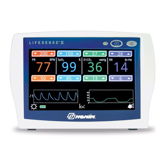
- Page 1 Operator’s Manual LifeSense ® Model LS1 Capnography/Pulse Oximetry Monitor English 0123 0123...
- Page 2 Nonin makes no claim for use of the product other than those uses specified herein and disclaims any liability resulting from other uses. Observe all warnings, cautions, and notes. Unauthorized use, copying, or distribution of this manual is prohibited without written consent from Nonin Medical, Inc.
-
Page 3: Table Of Contents
Contents Indications for Use ..................1 Warnings ....................... 1 Cautions ........................ 2 Guide to Symbols ..................5 Introduction....................7 About LifeSense II ....................7 About Capnometry....................7 About Pulse Oximetry.................... 7 System Components ..................8 LifeSense II Monitor....................9 Rechargeable Battery..................11 Battery Replacement .................. - Page 4 Contents (Continued) New PIN......................28 Factory Service....................28 Date/Time Screen ....................29 Alarm Lock Mode Screen..................30 Calibration Screen....................30 Calibration Procedure ..................30 Alarm Limit Settings ................... 32 Alarm Limits ......................32 Alarms ......................34 High Priority Alarms ..................... 34 Medium Priority Alarms ..................
- Page 5 Contents (Continued) Power Requirements ................... 52 Manufacturer’s Declaration.................. 53 Equipment Response Time ................. 55 Testing Summary ....................56 Accuracy Testing..................56 Pulse Rate Accuracy Testing ................56 Low Perfusion Accuracy Testing..............56 System Specifications ..................57 Pulse Oximeter Specifications................58 Capnography Specifications................
- Page 6 Figure 4. Operating Screen..................17 Figure 5. Trend Screen ..................... 20 Figure 6. Start-up Screen..................21 Figure 7. Access Configuration Menu (Nonin Logo) ..........24 Figure 8. Configuration Menu ................... 24 Figure 9. Language/Units Screen ................25 Figure 10. Responsible Organization Settings Screen ..........26 Figure 11.
- Page 7 Tables Table 1. Symbols....................... 5 Table 2. Monitor Features ..................10 Table 3. Select Alarm Group Screen – Display Descriptions ........16 Table 4. Operating Screen – Display Descriptions..........17 Table 5. Trend Screen – Display Descriptions ............20 Table 6. Alarm Limit Settings .................. 32 Table 7.
-
Page 8: Indications For Use
Never allow liquids to enter into or to be spilled onto the monitor. If liquid has penetrated into the monitor, it must be checked by Nonin Technical Service. This device is only defibrillation proof when used with Nonin-specified power supplies, cables, and accessories. To avoid patient injury, only use Nonin-specified power supplies, cables, and accessories (see Accessories). -
Page 9: Cautions
Indications for Use Warnings (Continued) The monitor displays a flashing yellow battery indicator (low battery) when it has approximately 60 minutes of use remaining before it shuts itself off. This device should not be used adjacent to or stacked with other equipment. If adjacent or stacked use is necessary, the device should be observed carefully to verify normal operation. - Page 10 This device contains WEEE materials; please contact your distributor regarding take back or recycling of the device. If you are unsure how to reach your distributor, please call Nonin for your distributor’s contact information.
- Page 11 Indications for Use Cautions (Continued) If the Nafion tubing becomes contaminated or damaged during use, discard it and replace it with a new one. A functional tester cannot be used to assess the accuracy of a pulse oximeter monitor or sensor. Portable and mobile RF communications equipment can affect medical electrical equipment.
-
Page 12: Guide To Symbols
15 degrees and against access to hazardous parts with a finger per IEC 60529. Green charging indicator (LED) On/Standby button Audio Pause button Power supply input USB port 2 Sensor input NONIN SpO Luer lock connector for sample line, Nafion tubing, or cannula Do not reuse (moisture trap) - Page 13 Guide to Symbols Table 1. Symbols (Continued) Symbol Description/Function Federal law (USA) restricts this device to sale by or on the order of a licensed practitioner. Manufacturer Catalogue number Serial number Quantity Temperature limitation for storage/shipping RoHS compliant (China) Date of manufacture Country of manufacture...
-
Page 14: Introduction
Pulse rate and SpO are measured by a Nonin-branded PureLight pulse oximetry sensor, provided with the system. Use only those accessories recommended by Nonin. Refer to the Accessories section for more information. The monitor has a touch screen display where settings and adjustments are made. The only buttons on the monitor, On/Standby (off) and Audio Pause, are located on the upper right corner of the front panel. -
Page 15: System Components
• LifeSense II monitor • Power supply and plug • Nonin PureLight reusable pulse oximetry sensor • Single-use, disposable moisture trap with filter • Single-use, disposable filters (qty 3) • Adult nasal cannula (qty 3) •... -
Page 16: Lifesense Ii Monitor
System Components LifeSense II Monitor ® Front Side MEDICAL EQUIPMENT 0123 0123 30EM MASS: 865g 12 VDC, 1.5A IP22 Nonin Medical, Inc. Plymouth, MN USA Use with Nonin Power Adapters Back Figure 1. Monitor Features... -
Page 17: Table 2. Monitor Features
System Components Table 2. Monitor Features No. Symbol/Name Description Touch Screen The monitor’s LCD displays parameters, graphs, menus, and other Display information.The display is a touch screen from which all operator-defined settings are made. See Display Screens section for additional screen information and descriptions. -
Page 18: Rechargeable Battery
A flashing red battery indicator (critical battery) displays when 10 minutes of power is left before the monitor switches itself off. Recharging a fully-depleted battery takes approximately 9 hours when using a Nonin-specified power supply. Always connect the monitor to an outlet whenever it is not in use. -
Page 19: Battery Replacement
Battery Replacement The battery, made of Lithium Ion (Li-Ion) rechargeable cells, is integral to the device and cannot be replaced by anyone other Nonin Technical Service. The life expectancy of the battery is approximately 1 year. CAUTION: Do not attempt to replace the battery inside the monitor. The battery is not field replaceable and cannot be replaced by the operator. -
Page 20: Nafion Tubing
System Components Nafion Tubing The Nafion tubing is a single-use, disposable component designed to be placed between the moisture trap and the nasal cannula or sample line to remove water vapor. Attaching the Nafion Tubing 1. Connect male end of the Nafion tubing to the moisture trap. Turn clockwise to tighten. 2. -
Page 21: Psg Dac Cables
Refer to the individual PSG DAC cable instructions for use for more information. Capno RTC Cable Nonin’s Capno RTC digital USB cable transmits real-time data from the monitor to another device (e.g., computer). Refer to the Capno RTC instructions for use for more information. -
Page 22: Display Screens
Display Screens Display Screens The following section describes the icons and their functions on the select alarm group, operating, and trend screens. Select Alarm Group Screen NOTE: This screen does not display if the monitor has locked alarm limits (see Alarm Lock Mode Screen section). -
Page 23: Table 3. Select Alarm Group Screen - Display Descriptions
Display Screens Table 3. Select Alarm Group Screen – Display Descriptions Description Alarm Limits ≤30kg / 66lbs Pressing this icon selects the default alarm limits for patients weighing 30 kg (66 lbs) or less. • If the Responsible Organization Settings have not been set, the alarm limits will be the factory default settings (see table 6). -
Page 24: Operating Screen
Display Screens Operating Screen The main operating screen (figure 4) displays parameters, graphs, and other information. NOTE: If a pop-up window displays while monitoring, the icons and alarm limit up/down arrows cannot be used until the pop-up window is closed. Figure 4. - Page 25 Display Screens Table 4. Operating Screen – Display Descriptions (Continued) Symbol/Name Description Displays the volume of end tidal CO in exhaled air. EtCO EtCO mmHg shown as mmHg or kPa. EtCO Displays the respiration rate in breaths per minute. BrPM Messages Shows pulse oximeter alarm messages.
-
Page 26: Trend Screen
Display Screens Table 4. Operating Screen – Display Descriptions (Continued) Symbol/Name Description Respiration Capnogram Displays a graph of the respiration and EtCO Brightness Pressing this icon allows the operator to change the brightness of the display while monitoring. Options are maximum (default), medium, and low. -
Page 27: Figure 5. Trend Screen
Display Screens Figure 5. Trend Screen Table 5. Trend Screen – Display Descriptions Description Trend Graphs – Pulse Rate (PR), SpO , EtCO , and Respiration Rate (RR) Trend Timescale Alarm Indicators Indicates the parameter’s reading is outside the defined high alarm limit. Indicates the parameter’s reading is outside the defined low alarm limit. -
Page 28: Using The Lifesense Ii Monitor
The lower left corner of the screen shows the monitor’s software revision. Verify each of the above items occur on initialization. If any do not occur, contact Nonin Technical Service Figure 6. Start-up Screen for assistance. If the clock is not set, the message “System Time is Not Set”... -
Page 29: Deep Sleep Mode
6. Connect the sample line to the connector on the moisture trap and secure it by turning the Luer lock connector clockwise. Only use sample lines recommended by Nonin (see Accessories). 7. See Monitoring a Patient. -
Page 30: Monitoring A Patient
Monitoring a Patient 1. Verify the system has been set up (see System Setup). 2. Apply the Nonin-branded sensor to the patient. 3. Attach the sample line to the patient, as described in Applying the Sample Line, or refer to the individual sample line instructions for use. -
Page 31: Configuration Menu
Access the Configuration Menu 1. Press On/Standby to turn the monitor on. 2. Start-up sequence begins. 3. When the Nonin logo start-up screen displays, press the Nonin logo twice (double-tap). In figure 7, the Nonin logo is highlighted with a white box. -
Page 32: Language/Units Screen
Using the LifeSense II Monitor Language/Units Screen This screen allows the operator to change the display language and the EtCO unit of measurement. This screen is accessed through the Configuration Menu (see Access the Configuration Menu). Defaults are English and mmHg. Set Language and/or Units of Measurement NOTE: When the Units of Measurement are changed, the Responsible Organization Settings revert to the factory defaults. -
Page 33: Responsible Organization Settings Screen
Using the LifeSense II Monitor Responsible Organization Settings Screen This screen allows the operator to establish institution default high and low limits for pulse rate, SpO EtCO , and respiration rate. This screen is accessed through the Configuration Menu (see Access the Configuration Menu). NOTES: •... -
Page 34: Minimum Alarm Volume
Using the LifeSense II Monitor Minimum Alarm Volume This setting controls the monitor’s available audible alarm volume levels. The default minimum alarm volume is Medium. Set the Minimum Alarm Volume 1. Access the Responsible Organization Settings screen. 2. In the Minimum Alarm Volume field, press one of the options. Options include Off, Medium (default), and Maximum. -
Page 35: Reset Device To Factory Defaults
New PIN again. 4. Press OK to save the new PIN. To exit without saving changes, press Cancel. 5. Display returns to the Responsible Organization Settings screen. Factory Service This feature is only used by Nonin Medical, Inc. -
Page 36: Date/Time Screen
Using the LifeSense II Monitor Date/Time Screen This screen allows the operator to set the monitor’s date and time (24-hour clock). The date/time is used in the file name when downloading data. If the operator will not be downloading data, setting the date/time is not required. -
Page 37: Alarm Lock Mode Screen
Using the LifeSense II Monitor Alarm Lock Mode Screen This screen allows the operator to set and lock the monitor’s alarm limits. NOTES: • The locked alarm limits cannot be set to limits outside of the Responsible Organization limits. • When alarm limits are locked, limits cannot be adjusted when monitoring. -
Page 38: Figure 13. Calibration Screen
(4.4 – 5.7 Vol%/kPa or 33 – 43 mmHg) an internal air leak is possible. Replace the single-use, disposable moisture trap and perform the calibration procedure. If the problem persists, contact Nonin Technical Service. -
Page 39: Alarm Limit Settings
Alarm Limit Settings Alarm Limit Settings If not locked, the operator can increase or decrease the alarm limit settings for individual patients. The alarm limit settings may be restricted by the Responsible Organization Settings. Press the up arrow to increase an alarm limit and the down arrow to decrease an alarm limit. - Page 40 Alarm Limit Settings WARNING: Ensure that all alarm volumes are audible in all situations. Do not cover or obstruct any speaker openings. CAUTION: Setting alarm limits to extremes can render the alarm system useless. CAUTION: The monitor is equipped with automatic barometric pressure compensation.
-
Page 41: Alarms
Alarms Alarms The monitor has audible and visual alarm indicators to alert the operator in case immediate patient attention is required or an equipment alarm occurs (figure 14). An audible or visual alarm remains active until the condition is no longer present. Each parameter can only have one high or low limit alarm at a time. -
Page 42: Table 7. High Priority Alarms
Alarms Table 7. High Priority Alarms Alarm Visual Indicator Audible Indicator PR High Limit – displays when pulse PR high limit flashes red 2 times 3 beeps, pause, rate is above the high alarm limit per second. 2 beeps, pause, 3 beeps, pause, 2 beeps, and a 6-second PR Low Limit –... -
Page 43: Medium Priority Alarms
Alarms Medium Priority Alarms A medium priority alarm indicates that an equipment fault has occurred and the device is unable to provide a measurement value. See table 8 for medium priority alarms. Medium priority alarms are both audible and visual. Table 8. -
Page 44: Inoperable Alarms
1. Turn the monitor off and then back on again to remove the error message. 2. If the error persists, note the error code and contact Nonin Technical Service at (800) 356- 8874 (USA and Canada), +1 (763) 553-9968, or +31 (0)13 - 79 99 040 (Europe). -
Page 45: Data Output And Software
8 GB SDCZ71-008G-A46 Cruzer Blade™ 4 GB SDCZ50-004G-A46 NOTE: If USB flash drive performance issues occur, see the Troubleshooting section for more information before contacting Nonin. Nonin cannot guarantee USB flash drive performance if a recommended flash drive is not used. -
Page 46: Download Data From The Monitor
Data Output and Software Download Data from the Monitor NOTE: Data cannot be downloaded if there is a medium or high priority alarm. 1. With the monitor on, but not connected to a patient, connect a USB flash drive to the monitor. 2. -
Page 47: Data Format
Data Output and Software Data Format The download directory name is the monitor’s serial number (XXXXXXXXX) followed by the current date and time. Example: XXXXXXXXX_YYYY_MM_dd_hh_mm_ss NOTE: If the correct date/time does not display, see Date/Time Screen for more information on setting the clock. -
Page 48: Monitor Software
LAL is the current lower alarm limit value for each parameter. Alarm volume is Off, Medium or Maximum. CRC is a 16-bit CCITT for the entire row. Monitor Software Visit nonin.com for more information about the monitor’s software, including the latest monitor software revision. -
Page 49: Connecting The Device Into A Medical System
Data Output and Software Connecting the Device into a Medical System Incorporating the device into a medical system requires the integrator to identify, analyze, and evaluate the risks to patient, operators, and third parties. Subsequent changes to the medical system after device integration could introduce new risks and will require additional analysis. -
Page 50: Maintenance And Inspection
Maintenance Ensuring Optimal Performance In order to ensure safety and optimal performance of the monitor, Nonin recommends a yearly inspection and functional check be performed on the monitor (see Recommended Inspections and Functional Check). The inspection and functional check may be performed by Nonin Technical Services or at your facility. -
Page 51: Recommended Inspections And Functional Check
CAUTION: This device is a precision electronic instrument and must be repaired by Nonin Technical Service. Field repair of the device is not possible. Do not attempt to open the case or repair the electronics. Opening the case may damage the device... -
Page 52: Troubleshooting
The table below lists common messages, descriptions, and actions to take. If these solutions do not correct the problem, please contact Nonin Technical Service at (800) 356- 8874 (USA and Canada), +1 (763) 553-9968, or +31 (0)13 - 79 99 040 (Europe). - Page 53 To prevent damage to the pump, the pump stops off. after 10 seconds of occlusion. See above for “OCCLUSION” message solutions. If the problem persists, contact Nonin Technical Service. Monitor has shut off. To avoid overheating, the See above for “OCCLUSION” message solutions.
- Page 54 This indicates Charge the monitor. Connect the monitor to the that a problem has power supply and the power supply to an outlet. occurred, possibly due to If the problem persists, contact Nonin Technical interference or software Service. issues. Low EtCO...
- Page 55 The PIN entered does not Enter the default PIN (0000). match the Factory PIN or If 0000 is not the correct PIN, contact Nonin the Responsible Technical Service. Organization PIN. “Calibration Due” pop- It has been 6 months since...
-
Page 56: Accessories
+31 (0)13 - 79 99 040 (Europe) • Visit www.nonin.com Nonin may update the accessories list at any time. It is the purchaser’s responsibility to always ask for the current list, by model number, when ordering accessories. Monitor Accessories... -
Page 57: Purelight Sensors
Accessories Item Description Nafion Tubing Single-use, disposable Perma Pure Nafion tubing to remove water vapor from the sample line. Verification Gas Verification gas and tubing. Contains 5 Vol% of CO (equals 38 mmHg or 5.3 kPa). To be used with a gas valve. Gas Valve for Reusable gas valve and tubing for controlling the flow from the verification gas. -
Page 58: Service, Support, And Warranty
Nonin shall repair or replace any LifeSense II found to be defective in accordance with this warranty, free of charge, for which Nonin has been notified by the purchaser by serial number that there is a defect, provided said notification occurs within the applicable warranty period. This warranty shall be the sole and exclusive remedy by the purchaser hereunder for any LifeSense II delivered to the purchaser which is found to be defective in any manner, whether such remedies be in contract, tort, or by law. -
Page 59: Technical Information
Rated supply voltages or voltage ranges for the power supply 100 – 240 VAC 50 – 60 Hz Input voltage from the power supply 12 VDC, 1.5 A WARNING: To avoid patient injury, only use Nonin-specified power supplies, cables, and accessories (see Accessories). -
Page 60: Manufacturer's Declaration
Technical Information Manufacturer’s Declaration See the following tables for specific information regarding this device’s compliance to IEC 60601-1-2. Table 11. Electromagnetic Emissions Emissions Test Compliance Electromagnetic Environment—Guidance This device is intended for use in the electromagnetic environment specified below. The user of this device should ensure that it is used in such an environment. -
Page 61: Table 13. Guidance And Manufacturer's Declaration-Electromagnetic Immunity
Technical Information Table 13. Guidance and Manufacturer’s Declaration—Electromagnetic Immunity IEC 60601 Immunity Test Compliance Level Electromagnetic Environment—Guidance Test Level This device is intended for use in the electromagnetic environment specified below. The user of this device should ensure that it is used in such an environment. -
Page 62: Equipment Response Time
Technical Information Table 14. Recommended Separation Distances This device is intended for use in an electromagnetic environment in which radiated RF disturbances are controlled. Customers or users of this device can help prevent electromagnetic interference by maintaining a minimum distance between portable and mobile RF communication equipment (transmitters) and the device as recommended below, according to maximum output power of the communications equipment. -
Page 63: Testing Summary
CAUTION: A functional tester cannot be used to assess the accuracy of a pulse oximeter monitor or sensor. Testing Summary accuracy and low perfusion testing were conducted by Nonin Medical, Inc., as described below: Accuracy Testing accuracy testing is conducted during induced hypoxia studies on healthy, non-smoking, light- to-dark-skinned subjects during motion and no-motion conditions in an independent research laboratory. -
Page 64: System Specifications
Technical Information System Specifications Power Requirements: 100 – 240 VAC 50 – 60 Hz Power Supply: Power Consumption: 3.6 W with battery operation Input: 9 W with power supply 12 VDC, 1.5 A Internal Battery: Type: Lithium Ion (Li-Ion) internal battery, non-field replaceable, rechargeable Battery Capacity: Approximately 5 hours... -
Page 65: Pulse Oximeter Specifications
Infrared: 660 nanometers @ 0.8 mW max. average Red: 910 nanometers @ 1.2 mW max. average Accuracy - Sensors: Declared accuracy data for compatible sensors can be found in Nonin’s Sensor Accuracy document. *This information is especially useful for clinicians performing photodynamic therapy. Capnography Specifications Respiration Range:...
Need help?
Do you have a question about the LS1 and is the answer not in the manual?
Questions and answers