Nonin 7500FO Operator's Manual
Digital pulse oximeter
Hide thumbs
Also See for 7500FO:
- Quick manual (2 pages) ,
- Operator's manual (42 pages) ,
- Instructions for use (2 pages)
Table of Contents
Advertisement
Quick Links
Download this manual
See also:
Quick Manual
Advertisement
Table of Contents

Related Manuals for Nonin 7500FO


Summary of Contents for Nonin 7500FO
- Page 1 Operator’s Manual Model 7500FO Model 7500FO Digital Pulse Oximeter English 0123...
- Page 2 MPS, Medical Product Service GmbH Borngasse 20 D-35619 Braunfels, Germany References to “NONIN” in this manual shall imply Nonin Medical, Inc. NONIN, Flexi-Form, FlexiWrap, PureLight and nVISION are registered trademarks or trademarks of Nonin Medical, Inc. Microsoft® and Windows® are registered trademarks of Microsoft Corporation.
-
Page 3: Table Of Contents
Contraindications ..............3 Warnings ................... 3 Cautions ..................4 Displays, Indicators and Controls ........7 Operating the Model 7500FO ..........11 Operating Instructions .............12 Operating in the MR Environment ...........12 Operating Modes and Defaults ........14 Setup Mode, Viewing Limits and Setting Time ......14 Factory Defaults ..............14... - Page 4 Technical Information ............38 Manufacturer’s Declaration .............38 Equipment Response Time .............42 Testing Summary ..............43 Specifications ................44...
-
Page 5: Guide To Symbols
Guide to Symbols This table describes the symbols that are found on the Model 7500FO. Detailed information about functional symbols can be found in “Operating the Model 7500FO.” Symbol Description Caution! Consult Instructions for Use. Type BF Applied Part (Patient isolation from electrical shock). - Page 6 Symbol Description Alarm Bar LED. Pulse Quality LED. Sensor Alarm LED. Pulse Strength Bargraph LED. Alarm Silence LED. AC Power Adapter LED. Low Battery LED. ON/STANDBY button. Alarm Silence button. Limits button. Plus button. Minus button. Non-ionizing electromagnetic radiation. Equipment includes RF transmitters;...
-
Page 7: Indications For Use
• As with all medical equipment, carefully route patient cables and connections to reduce the possibility of entanglement or strangulation. • Use this device only with power adapters supplied by NONIN Medical. • This device turns off after approximately 30 minutes when in low battery mode. -
Page 8: Cautions
• To avoid injury or potential equipment damage, always keep the oximeter, battery charger and metal end of fiber optic cable beyond the distance of magnetic attraction. To ensure safe operation of the 7500FO in the MR environment, the monitor must be located outside the 200 Gauss line of the MR room and must be firmly attached to a fixed object. - Page 9 This device contains WEEE materials; please contact your distributor regarding take-back or recycling of the device. If you are unsure how to reach your distributor, please call NONIN for your distributor’s contact information. • To prevent potential loss of monitoring or inaccurate data, remove any objects that might hinder pulse detection and measurement (e.g., blood...
- Page 10 Cautions (Continued) • This device is designed to determine the percentage of arterial oxygen saturation of functional hemoglobin. Factors that may degrade pulse oximeter performance or affect the accuracy of the measurement include the following: - excessive ambient light - excessive motion - electrosurgical interference - blood flow restrictors (arterial catheters, blood pressure cuffs, infusion lines, etc.)
-
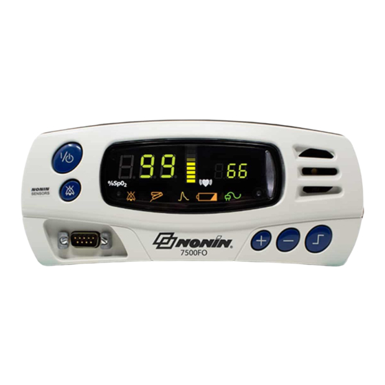
Page 11: Displays, Indicators And Controls
Connector %SpO Display The %SpO display is located on the left-hand side of the Model 7500FO front panel and is identified by the %SpO symbol. This display shows blood oxygen saturation, from 0 to 100 percent. The numeric displays blink during SpO alarm conditions. -
Page 12: Numeric Leds
This amber LED indicates when a sensor has become disconnected, has failed, or is not compatible with this monitor. NOTE: In the 7500FO, the Sensor Alarm LED latches. Sensor must be properly attached to patient and alarm silence button must be toggled to clear LED. - Page 13 This amber LED indicates a low battery charge when blinking, and a critical battery charge when lit solidly. This LED does not indicate that the Model 7500FO is running on battery power. WARNING: This device turns off after approximately 30 minutes when in low battery mode.
- Page 14 Plus (+) and Minus (-) buttons. Plus (+) and Minus (-) Buttons These buttons adjust values for many Model 7500FO functions. The Plus (+) and Minus (-) buttons are used to adjust time, date, volume and upper and lower alarm limits, except in Patient...
-
Page 15: Operating The Model 7500Fo
• Before using the Model 7500FO, please review all contraindications, warnings and cautions. • Before using the Model 7500FO, the battery must be charged for four (4) hours. • When the Model 7500FO reaches critical battery, a medium priority alarm will sound. -
Page 16: Operating Instructions
WARNING: To avoid injury or potential equipment damage, always keep the oximeter and metal end of fiber optic cable beyond the distance of magnetic attraction. To ensure safe operation of the 7500FO in the MR environment, the monitor must be located outside the 200 Gauss line of the MR room and must be firmly attached to a fixed object. - Page 17 (1/4-20 thread) on the bottom of the device. • If interference is suspected to the MR image or to the 7500FO, contact NONIN Technical Service at (800) 356-8874 or (763) 553-9968 for assistance.
-
Page 18: Operating Modes And Defaults
In Factory Defaults, all adjustable parameters are set as indicated in the table below. This is the Model 7500FO’s default operating setting. The Model 7500FO is shipped with factory defaults active. To revert to factory default alarm limits from the user-defined default alarm limits, simultaneously press the alarm silence and minus (-) buttons. -
Page 19: User-Defined Defaults
All user-defined default settings are retained even when both external and battery power are lost. Patient Security Mode Alarm limits cannot be changed when the Model 7500FO is in Patient Security mode. Patient Security mode prevents accidental changes to critical parameters. The Model 7500FO allows users to lock and unlock alarm limits, volume settings, and time settings through the use of Patient Security mode. - Page 20 In Patient Security mode, operators cannot view or set the time and date. When the Model 7500FO is turned on in Patient Security mode, “SEC on” is displayed in the display area, and three informational tones sound. The upper alarm limits are then displayed, followed by the lower alarm limits.
-
Page 21: Operator Functions
Operator Functions The Model 7500FO has several easy-to-use basic functions. Most involve pressing only a single button. Function Button Instruction Turn the Model Press the ON/STANDBY button to turn on 7500FO on and the Model 7500FO. Press and hold the off. - Page 22 Table 1: Limits Display Sequence Initial Parameter Setting (SpO 2 ) (Pulse Rate Parameter Adjustment Range Display Display) Recall Alarm Settings “rCL” “no” “yES” or “no” Low %SpO Alarm Limit “85” “Off”, 50 to 95 by 1 “02L” Pulse High Alarm Limit “200”...
- Page 23 Model 7500FO). NOTE: Alarm limits cannot be changed when the Model 7500FO is in Patient Security mode. Patient Security mode prevents accidental changes to critical parameters. The Model 7500FO allows users to lock and unlock alarm limits, volume settings, and time settings.
-
Page 24: Function Button
Function Button Instruction Make Current To set the User-Defined Defaults to the Alarm Values current alarm settings, hold the Alarm User-defined Silence button and then press the Limits Defaults button. Revert to To revert to the factory defaults, from the Factory User-Defined Defaults alarm limits, hold Defaults... -
Page 25: Care And Maintenance
10% bleach (5.25% sodium hypochlorite) with water solution. Do not pour or spray any liquids onto the Model 7500FO, and do not allow any liquid to enter any openings in the device. Allow the unit to dry thoroughly before reusing it. -
Page 26: Alarms And Limits
Watchdog alarms are loud, two-tone, steadily beeping signals that indicate a hardware or software malfunction. When a watchdog alarm is activated, it can be cleared by shutting down the Model 7500FO. If the watchdog alarm cannot be cleared, remove power and contact your distributor or NONIN Technical Service. -
Page 27: Alarm Summary
Alarm Summary The Model 7500FO detects both patient and equipment alarms. In general, patient alarms are identified as high priority, while equipment alarms are identified as medium priority. High priority alarms always take priority over medium priority alarms. Alarm indicators remain active for as long as the alarm condition is present. -
Page 28: Reviewing And Setting Volume And Alarm Limits
Reviewing and Setting Volume and Alarm Limits NOTE: Alarm limits reset themselves to default values each time the unit is powered up—unless the unit is in Patient Security mode. In Patient Security mode, alarm limits and volumes cannot be adjusted; they can only be viewed. WARNING: To comply with relevant product safety standards, ensure that all alarm volumes are set appropriately and are audible in all situations. -
Page 29: Recalling Previous Settings
If the error persists, disconnect all power, and then reconnect the power and turn the unit back on. If the error still persists, note the error code and contact NONIN Technical Service at (800) 356-8874 (USA and Canada) or +1 (763) 553-9968... -
Page 30: Memory And Data Output Features
Model 7500FO to the receiving computer. The information from the Model 7500FO is sent in an ASCII serial format at 9600 baud with 8 data bits, 1 start bit, and 2 stop bits. Each line is terminated by CR/LF. -
Page 31: Analog Output
Pulse Rate Analog Output Accuracy ±5% Analog Output Calibration Analog calibration signals that allow external device calibration are provided after initial power up, and continue until the Model 7500FO begins tracking SpO and pulse rate readings. The calibration routine ends when the system begins tracking signals. The calibration signal... -
Page 32: Memory Features
Memory Features The Model 7500FO can collect and store 70 hours of continuous SpO and pulse rate information. Data may be played back with data retrieval software (NONIN’s nVISION software is recommended). If you wish to create your own software, contact NONIN for the data format. - Page 33 When Memory Playback is complete, the device will return to normal operation. NOTES: • Patient memory cannot be cleared when the Model 7500FO is in Patient Security mode. • If using nVISION software, select the Model 2500 option for model type (the...
-
Page 34: Parts And Accessories
Parts and Accessories The following NONIN accessories function with the Model 7500FO. Detailed information regarding specified sensor use (patient population, body/tissue, and application) can be found in the respective sensor instructions. Model Number Description AvantB Battery Pack 7500FO Manual Operator’s Manual for the Model 7500FO... - Page 35 For more information about NONIN parts and accessories, contact your distributor, or contact NONIN at (800) 356-8874 (USA and Canada) or (763) 553-9968. This information is also available on the NONIN website: www.nonin.com. WARNING: The use of accessories, sensors, and cables other than those listed in this manual may result in increased electromagnetic emission and/or decreased immunity of this device.
-
Page 36: Service, Support, And Warranty
Service, Support, and Warranty A return authorization number is required before returning any product to NONIN. To obtain this return authorization number, contact NONIN Technical Service: Nonin Medical, Inc. 13700 1st Avenue North Plymouth, Minnesota 55441-5443 USA (800) 356-8874 (USA and Canada) +1 (763) 553-9968 (outside USA &... -
Page 37: Warranty
Model 7500FO battery pack. NONIN warrants the pulse oximetry module of the Model 7500FO for a period of three years from the date of purchase. Extended warranties are available on most NONIN pulse oximeter models. -
Page 38: Troubleshooting
Model 7500FO will The unit has no power. Plug in the AC adapter. not activate. Model 7500FO will The battery pack is not Plug in the Model 7500FO AC not operate on charged. Adapter to charge the battery pack. batteries. - Page 39 • infusion line The red LED is not lit Ensure the sensor is securely in the sensor’s finger attached to the Model 7500FO. insertion area. Check the sensor for any visible signs of deterioration. Contact NONIN Technical Service. Frequent or...
- Page 40 The finger was Reinsert the finger and keep the removed from the sensor motionless for at least 10 sensor. seconds. The Model 7500FO is Turn the unit off, check all not functioning. connections, and retry. Contact NONIN Technical Service. An error code...
- Page 41 The battery is missing. Contact your distributor or NONIN record data. Technical Service for repair or replacement. If these solutions do not correct the problem, please contact NONIN Technical Service at (800) 356-8874 (USA and Canada) or +1 (763) 553-9968.
-
Page 42: Technical Information
Technical Information NOTE: This product complies with ISO 10993-1, Biological Evaluation of Medical Devices Part 1: Evaluation and Testing. CAUTION: A functional tester cannot be used to assess the accuracy of a pulse oximeter monitor or sensor. CAUTION: All parts and accessories connected to the serial port of this device must be certified according to at least IEC Standard EN 60950 or UL 1950 for data-processing equipment. - Page 43 Table 3: Electromagnetic Immunity Electromagnetic IEC 60601 Test Compliance Immunity Test Environment— Level Level Guidance This device is intended for use in the electromagnetic environment specified below. The user of this device should ensure that it is used in such an environment. Electrostatic ±6 kV contact ±6 kV contact...
- Page 44 Table 4: Guidance and Manufacturer’s Declaration— Electromagnetic Immunity Immunity IEC 60601 Compliance Electromagnetic Test Test Level Level Environment—Guidance This device is intended for use in the electromagnetic environment specified below. The user of this device should ensure that it is used in such an environment. Portable and mobile RF communications equipment should be used no closer to any part of the device, including cables, than the recommended separation distance calculated from the equation applicable to the frequency of the transmitter.
- Page 45 Table 5: Recommended Separation Distances This table details the recommended separation distances between portable and mobile RF communications equipment and this device. This device is intended for use in an electromagnetic environment in which radiated RF disturbances are controlled. Users of this device can help prevent electromagnetic interference by maintaining a minimum distance between portable and mobile RF communication equipment (transmitters) and the device as recommended below, according to maximum output power of the...
-
Page 46: Equipment Response Time
Equipment Response Time Values Average Latency Standard/Fast Averaged SpO 4 beat exponential 2 beats Pulse Rate Values Response Latency Standard/Fast Averaged Pulse Rate 4 beat exponential 2 beats Example - SpO Exponential Averaging decreases 0.75% per second (7.5% over 10 seconds) Pulse Rate = 75 BPM SaO2 Reference 4 Beat Average... -
Page 47: Testing Summary
Testing Summary accuracy, and low perfusion testing were conducted by NONIN Medical, Inc., as described below: Accuracy Testing accuracy testing is conducted during induced hypoxia studies on healthy, non-smoking, light- to dark-skinned subjects during motion and no-motion conditions in an independent research laboratory. The... -
Page 48: Specifications
Specifications Oxygen Saturation Display Range: 0 to 100% SpO Pulse Rate Display Range 18 to 321 pulses per minute (BPM) Displays: Pulse Quality: LED, amber Sensor Alarm: LED, amber Pulse Strength Bargraph: LED, bargraph, tri-color segments Alarm Indicator: LED, bi-color Alarm Silenced: LED, amber Numeric Displays: 3-digit, 7-segment LEDs, green Low Battery: LED, amber... - Page 49 Dimensions Approximately 219 mm (8.6”) W x 92 mm (3.6”) H x 142 mm (5.6”) D Weight Approximately 900 grams (2 lbs) with battery Warranty 3 years Classification per IEC 60601-1/CSA601.1/UL60601-1 30EM: Type of Protection: Internally powered (on battery power). Class I with AC adapter.
Need help?
Do you have a question about the 7500FO and is the answer not in the manual?
Questions and answers