Nonin 2500 PalmSAT Operator's Manual
Hide thumbs
Also See for 2500 PalmSAT:
- Instructions for use (2 pages) ,
- Instructions for use manual (6 pages)
Table of Contents
Advertisement
Advertisement
Table of Contents

Related Manuals for Nonin 2500 PalmSAT


Summary of Contents for Nonin 2500 PalmSAT
- Page 1 Operator’s Manual ® Model 2500 PalmSAT Pulse Oximeter English 0123 0123...
- Page 2 Authorized EC Representative: MPS, Medical Product Service GmbH Borngasse 20 D-35619 Braunfels, Germany References to “Nonin” in this manual shall imply Nonin Medical, Inc. Nonin, PalmSAT, PureLight and nVISION are registered trademarks or trademarks of Nonin Medical, Inc. ® ® Microsoft and Windows are registered trademarks of Microsoft Corporation.
-
Page 3: Table Of Contents
Contents Indications for Use ..................1 Contraindications....................1 Warnings ........................ 1 Cautions ......................... 2 Guide to Symbols ..................4 Displays and Indicators ................5 Display ......................5 Pulse Rate Display ....................5 Pulse Quality Display....................5 Low Battery Indicator....................5 Sensor Fault or Inadequate Signal Display ............ - Page 4 Contents (Continued) Parts and Accessories.................21 Troubleshooting ...................22 Technical Information ..................24 Manufacturer’s Declaration ...................24 Equipment Response Time...................27 Testing Summary ....................28 Accuracy Testing ..................28 Pulse Rate Motion Testing.................28 Low Perfusion Testing ..................28 Principles of Operation..................29 Specifications ......................29...
- Page 5 Figures Figure 1. Displays, Indicators and Buttons..............6 Figure 2. Rear View....................7 Figure 3. Installing Batteries..................8 Figure 4. Connecting a Sensor................. 10...
- Page 6 Tables Table 1. Labeling Symbols..................4 Table 2. Adjustable Parameters and Settings............12 Table 3. Pulse Oximeter Sensor Connector Pin Assignments......... 18 Table 4. Electromagnetic Emissions................ 24 Table 5. Electromagnetic Immunity................25 Table 6. Guidance and Manufacturer’s Declaration—Electromagnetic Immunity..26 Table 7.
-
Page 7: Indications For Use
Use only with Nonin-branded PureLight pulse oximeter sensors. These sensors are manufactured to meet the accuracy specifications for Nonin Pulse Oximeters. Using other manufacturers’ sensors may cause improper pulse oximeter performance. Using other manufacturers’ sensors can result in improper pulse oximeter performance. -
Page 8: Cautions
Verify that all visible indicators illuminate during the startup (initialization) sequence. If any indicator is not lit, do not use the device. Contact Nonin Technical Service for assistance. The presence of a defibrillator may interfere with the performance of this device. - Page 9 Do not attempt to open the case or repair the electronics. Opening the case may damage the device and void the warranty. Any sign or evidence of opening the system, field service by non-Nonin personnel, tampering, or any kind of misuse or abuse of the system, shall void the warranty in its entirety.
-
Page 10: Guide To Symbols
Guide to Symbols Guide to Symbols This table describes the symbols that are found on the Model 2500 and in this manual. Table 1: Labeling Symbols Symbol Description Consult Instructions for Use. Follow Instructions for Use. Type BF Applied Part (Patient isolation from electrical shock). UL Mark for Canada and the United States with respect to electric shock, fire, and mechanical hazards only in accordance with UL 60601-1 and CAN/CSA- C22.2 No. -
Page 11: Displays And Indicators
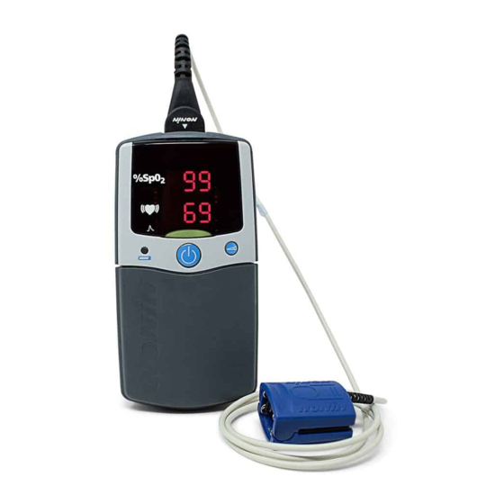
Displays and Indicators Displays and Indicators Display The SpO display is the upper numeric display (identified by the %SpO symbol). This 3-digit light-emitting diode (LED) display shows the current oxygen saturation percentage. Pulse Rate Display The Pulse Rate display is the lower numeric display (identified by the symbol). -
Page 12: Using The Palmsat Pulse Oximeter
Using the PalmSAT Pulse Oximeter Using the PalmSAT Pulse Oximeter The Model 2500 PalmSAT is a digital handheld pulse oximeter that displays numerical values for blood oxygen saturation (%SpO ) and pulse rate. This device will typically operate for 80 hours continuously between alkaline battery replacements, or for 40 hours with the Model 2500B Rechargeable NiMH (Nickel Metal Hydride) Battery Pack (optional). -
Page 13: Unpacking The Model 2500
Using the PalmSAT Pulse Oximeter The Model 2500 Pulse Oximeter may be used with a variety of Nonin-branded PureLight pulse oximeter sensors. A sensor disconnect or malfunction is indicated by an inadequate Pulse Quality display blinking and/or a dash to the left of the SpO value on the LED display. -
Page 14: Figure 3. Installing Batteries
Using the PalmSAT Pulse Oximeter When batteries are critically low, the digital displays will go blank, and the Pulse Quality display will blink amber or red, but not green. After 10 minutes at critically low battery capacity, the pulse oximeter will shut off automatically. WARNING: The device turns off after approximately 10 minutes when at critically low battery capacity. -
Page 15: Important Notes About Battery Use
Using the PalmSAT Pulse Oximeter Important Notes about Battery Use Four AA alkaline batteries provide the device with approximately 80 hours of continuous operation, while the Rechargeable NiMH Battery Pack provides approximately 40 hours of continuous operation. Clock/calendar settings can significantly affect battery storage life. Batteries drain during storage, but they drain much more quickly when the unit’s clock/calendar functions are set. -
Page 16: Connecting The Sensor
Using the PalmSAT Pulse Oximeter Connecting the Sensor Connect the pulse oximeter sensor (with the Nonin logo facing up) to the top of the device as shown. Ensure that the sensor is firmly plugged in. Refer to “Specifications” or to the specific sensor package insert for pulse oximeter sensor positioning information. -
Page 17: Monitoring
Using the PalmSAT Pulse Oximeter Monitoring Verify that the pulse oximeter sensor is properly positioned on the patient. Ensure that the pulse oximeter is sensing adequate pulse quality by: • verifying that the Pulse Quality display is blinking green and •... -
Page 18: Detailed Operation
Detailed Operation Detailed Operation All functions of the Model 2500 are controlled by the On/Off and Advance buttons located on the front of the unit. Setup Mode Setup mode is used to set: 1. memory clear function, 2. calendar and clock, and 3. - Page 19 Detailed Operation Table 2: Adjustable Parameters and Settings (Continued) Appears in SpO Range of Values Appears in Default Setting Pulse Rate Display Value Display Month 00 - 12 01 - 31 Hour 00 - 23 Minute 00 - 59 a. Choosing “yes” for both the CLr and dEL settings (the memory clear function) will clear the memory and exit setup mode.
-
Page 20: Care And Maintenance
Care and Maintenance Care and Maintenance Clean the device separately from the sensors. For instructions on cleaning pulse oximeter sensors, refer to the respective sensor instructions for use. CAUTION: Do not autoclave or immerse the device or sensors in liquid. Do not expose the device or components to excessive moisture or liquids. -
Page 21: Visual Indicators
Visual Indicators Visual Indicators The following table describes visual indicators and conditions. Condition Visible Indication • Pulse Quality LED blinks red Pulse Waveform Signal is • SpO and heart rate LEDs display dashes after inadequate 10 seconds • Pulse Quality LED blinks Sensor fault (i.e., sensor •... -
Page 22: Memory Functions
30 seconds after removing the batteries. Replace batteries immediately to avoid losing stored data. Nonin’s nVISION data management software is available for use with Microsoft Windows 2000/ XP/Vista/7 operating systems. The memory in the device functions as an “endless loop.” When the memory fills up, the unit begins overwriting the oldest data with the newest. -
Page 23: Clearing The Memory
Memory Functions Clearing the Memory The Memory Clear function allows you to delete all data currently stored in memory. Clear Memory Mode 1. Enter Setup mode; CLr no will be displayed. 2. CLr may be set to no or yES. •... -
Page 24: Communications
Communications Communications Serial Output The Model 2500 provides real-time data output capability via the pulse oximeter sensor connector (a 9-pin Sub-D connector). The pulse oximeter sensor connector pin assignments are listed below. Table 3: Pulse Oximeter Sensor Connector Pin Assignments Pin Number Assignment ®... -
Page 25: Service, Support And Warranty
Fax: +31 (0)13 - 79 99 042 E-mail: technicalserviceintl@nonin.com nonin.com All non-warranty work shall be done according to Nonin standard rates and charges in effect at the time of delivery to Nonin. All repairs include a complete retest of the Model 2500 using factory test fixtures. -
Page 26: Warranty
This warranty excludes cost of delivery to and from Nonin. All repaired units shall be received by the purchaser at Nonin's place of business. Nonin reserves the right to charge a fee for a warranty repair request on any device that is found to be within specifications. -
Page 27: Parts And Accessories
For more information about Nonin parts and accessories: • See the Parts and Accessories List on the Operator’s Manual CD. • Contact your distributor or Nonin at (800) 356-8874 (USA and Canada), +1 (763) 553-9968, or +31 (0)13 - 79 99 040 (Europe). -
Page 28: Troubleshooting
Figure 3: incorrectly. The device won’t turn on. Installing Batteries section of this operator’s manual. A metal contact in the battery Contact Nonin Technical compartment is missing or Service. damaged. A sensor fault exists Verify that the sensor is... - Page 29 Sensor failure. Replace the sensor. Note: If these solutions do not correct the problem with your device, please contact Nonin Technical Service at (800) 356-8874 (USA and Canada) or +1 (763) 553-9968, or +31 (0)13 - 79 99 040 (Europe).
-
Page 30: Technical Information
Technical Information Technical Information NOTE: This product complies with ISO 10993-1, Biological Evaluation of Medical Devices Part 1: Evaluation and Testing. CAUTION: A functional tester cannot be used to assess the accuracy of a pulse oximeter monitor or sensor. CAUTION: All parts and accessories connected to the serial port of this device must be certified according to at least IEC Standard EN 60950 or UL 1950 for data- processing equipment. -
Page 31: Table 5. Electromagnetic Immunity
Technical Information Table 5: Electromagnetic Immunity IEC 60601 Test Electromagnetic Immunity Test Compliance Level Level Environment—Guidance This device is intended for use in the electromagnetic environment specified below. The user of this device should ensure that it is used in such an environment. Electrostatic ±6 kV contact ±6 kV contact... -
Page 32: Table 6. Guidance And Manufacturer's Declaration-Electromagnetic Immunity
Technical Information Table 6: Guidance and Manufacturer’s Declaration—Electromagnetic Immunity IEC 60601 Compliance Electromagnetic Environment— Immunity Test Test Level Level Guidance This device is intended for use in the electromagnetic environment specified below. The user of this device should ensure that it is used in such an environment. Portable and mobile RF communications equipment should be used no closer to any part of the device, including cables, than the recommended separation distance calculated from the equation applicable to the frequency of the transmitter. -
Page 33: Equipment Response Time
Technical Information Table 7: Recommended Separation Distances This table details the recommended separation distances between portable and mobile RF communications equipment and this device. This device is intended for use in an electromagnetic environment in which radiated RF disturbances are controlled. -
Page 34: Testing Summary
Tim e in seconds • The response of the 4-beat average is 1.5 seconds. Testing Summary accuracy, and low perfusion testing was conducted by Nonin Medical, Inc., as described below: Accuracy Testing During motion and no-motion conditions at an independent research laboratory, SpO... -
Page 35: Principles Of Operation
18 to 321 beats per minute (BPM) Accuracy – Sensors Declared accuracy data for compatible sensors can be found in Nonin’s Sensor Accuracy document. Measurement Wavelengths and Output Power* Red: 660 nanometers @ 0.8 mW max. avg. Infrared: 910 nanometers @ 1.2 mW max. avg.
Need help?
Do you have a question about the 2500 PalmSAT and is the answer not in the manual?
Questions and answers