Xerox phaser 6250 Service Manual
Hide thumbs
Also See for phaser 6250:
- Manual (39 pages) ,
- Quick reference manual (11 pages) ,
- Setting instructions manual (9 pages)
Table of Contents
Advertisement
Quick Links
Advertisement
Table of Contents
Troubleshooting

Related Manuals for Xerox phaser 6250


Summary of Contents for Xerox phaser 6250
- Page 1 6250 P h a s e r ® C o l o r L a s e r P r i n t e r Service Manual...
- Page 2 manuals4you.com manuals4you.com...
-
Page 3: Phaser 6250
® Phaser 6250 Color Laser Printer Service Manual Warning The following servicing instructions are for use by qualified service personnel only. To avoid personal injury, do not perform any servicing other than that contained in the operating instructions, unless you are qualified to do so. - Page 4 ® As an Energy Star partner, Xerox Corporation has determined that this product meets the Energy Star guidelines for energy efficiency. The Energy Star name and logo are registered U.S. marks. manuals4you.com manuals4you.com...
-
Page 5: Service Terms
Product Terms Caution: A personal injury hazard exists that may not be apparent. For example, a panel may cover the hazardous area. Danger: A personal injury hazard exists in the area where you see the sign. Phaser 6250 Color Printer... -
Page 6: Symbols Marked On The Product
Symbols Marked on the Product DANGER high voltage. Protective ground (earth) symbol. Hot surface on or in the printer. Use caution to avoid personal injury. The surface is hot while the printer is running. After turning off the power, wait 30 minutes. 30 min. -
Page 7: Power Safety Precautions
■ if the printer is exposed to any excess moisture, ■ if the printer is dropped or damaged, ■ if you suspect that the product needs servicing or repair, ■ whenever you clean the product. Phaser 6250 Color Printer... -
Page 8: Electrostatic Discharge (Esd) Precautions
Electrostatic Discharge (ESD) Precautions Some semiconductor components , and the respective sub-assemblies that contain them, are vulnerable to damage by Electrostatic discharge (ESD). These components include Integrated Circuits (ICs), Large-Scale Integrated circuits (LSIs), field-effect transistors and other semiconductor chip components. The following techniques will reduce the occurrence of component damage caused by static electricity. -
Page 9: Service Safety Summary
When servicing the printer or laser unit, follow the procedures specified in this manual and there will be no hazards from the laser. viii Phaser 6250 Color Printer... -
Page 10: Servicing Electrical Components
Servicing Electrical Components Before starting any service procedure, switch off the printer power and unplug the power cord from the wall outlet. If you must service the printer with power applied, be aware of the potential for electrical shock. Warning Turning the power off by using the On/Off switch does not completely de- energize the printer. -
Page 11: Regulatory Specifications
The equipment described in this manual generates and uses radio frequency energy. If it is not installed properly in strict accordance with Xerox instructions, it may cause interference with radio and television reception or may not function properly due to interference from another device. -
Page 12: Declaration Of Conformity
Declaration of Conformity Xerox Corporation, declares, under our sole responsibility that the printer to which this declaration relates, is in conformity with the following standards and other normative documents: In the European Union following the provisions of the Low Voltage Directive 73/23/EEC and its... - Page 13 This product, if used properly in accordance with the user's instructions is neither dangerous for the consumer nor for the environment. A signed copy of the Declaration of Conformity for this product can be obtained from Xerox. Phaser 6250 Color Printer...
-
Page 14: Table Of Contents
Exterior..........1-5 Phaser 6250 Front Panel Configuration ......1-6 Rear View . - Page 15 Consumable Errors ........3-37 Phaser 6250 Color Printer...
- Page 16 [Y] [M] [C] [K] Toner Cartridge Failure ....3-77 Non-Phaser 6250 Fuser ....... 3-78 Non-Phaser 6250 Imaging Unit .
- Page 17 Black Prints with White Margin Border ....5-14 Solid Dark or Dirty Prints, No Border..... 5-15 Phaser 6250 Color Printer...
- Page 18 Missing Band, Voids Or Streaks In a Single Color or All Colors Parallel to the Leading Edge....5-16 Missing Band, Voids or Streaks in a Single Color or All Colors in Direction of Paper Travel .
- Page 19 Tray 1 Paper Pick Assembly (PL 6.1.27) (Roll Feed) ..8-58 Tray 1 Feed Solenoid (PL 6.1.40)......8-59 xviii Phaser 6250 Color Printer...
- Page 20 Tray 1 Shaft (PL 6.1.28)....... 8-60 Tray 1 Bottom Plate (PL 6.1.42)......8-61 Chute Assembly Exit .
- Page 21 ..........9-21 Phaser 6250 Color Printer...
- Page 22 PL 15.5 500-sheet Feeder Harness, Board and Motor ..9-50 Xerox Supplies and Accessories ......9-51 10 Wiring Diagrams Plug/Jack Locator Maps .
- Page 23 Printer Status Codes ........A-2 Index xxii Phaser 6250 Color Printer...
-
Page 24: General Information
General Information In this chapter... ■ Printer Introduction and Overview ■ Printer Configurations ■ Parts of the Printer ■ Phaser 6250 Front Panel Configuration ■ Image Processor Board ■ Routine Maintenance Items ■ Printer Specifications Chapter manuals4you.com manuals4you.com... -
Page 25: Printer Introduction And Overview
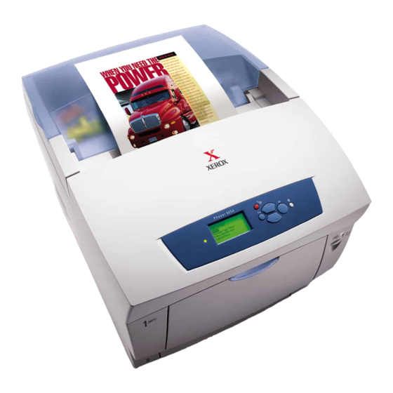
6250-010 Printer Configurations The Phaser 6250 Printer combines a single-pass, tandem color laser design, with an image processor supporting PostScript 3 and PCL5c page description languages. The printer is a high performance, A4, 26 page per minute (ppm) desktop color laser printer supporting resolutions up to 2400 x 600 dots-per-inch (dpi). - Page 26 A replaceable “Configuration Chip” holds configuration information that enables or disables built-in features as described below. Printer Configuration Features 6250B 6250N 6250DP 6250DT 6250DX Max Print Speed Memory (Mbytes) PostScript Fonts PCL Fonts Embedded PCL Job Pipelining Secure, Proof, and Saved Opt* Opt* Opt*...
-
Page 27: Printer Memory And Ram Capabilities
3.3 Volt The startup Page and the Configuration Page list the amount of RAM installed in the Printer. If the memory does not meet the above specifications, it will be ignored by the printer. Phaser 6250 Color Laser Printer Service Manual... -
Page 28: Parts Of The Printer
Parts of the Printer Exterior 6250-021 Top Cover (Output Tray) High-Capacity Feeder with Tray 3 and Tray 4 Control Panel (Front Panel) Door Latch B Front Cover Door Latch A Tray 1 (Multi-Purpose Tray) Power On/Off Switch Tray 2 (Universal Paper Tray) General Information manuals4you.com manuals4you.com... -
Page 29: Phaser 6250 Front Panel Configuration
Front Panel Shortcuts Mode Press this selection at Power On Skip execution of POST diagnostics Print Service Diagnostics Map INFO Reset PostScript NVRAM BACK+OK Password Bypass UP+DOWN Enter Service Diagnostics BACK+INFO Phaser 6250 Color Laser Printer Service Manual... -
Page 30: Rear View
Rear View 6250-019 Top Cover Paper Tray Rear Cover Toner Cartidges USB Connector AC Power Connector Ethernet 10BaseT and 100Tx Connector Image Processor Board IEEE 1284 Parallel Connector Rear Panel Configuration Interfaces ■ IEEE 1284 Parallel ■ Ethernet 10BaseT and 100Tx ■... -
Page 31: Image Processor Board
Store/Restore functions is available in "Service Diagnostic Tests" on page 3-9. pin 1 6250-023 Hard Drive (available option) NVRAM Configuration Chip Memory (RAM) DIMM 1 and DIMM 2 (available option) Phaser 6250 Color Laser Printer Service Manual... -
Page 32: Routine Maintenance Items
Routine Maintenance Items A printer part or assembly that has a limited life, and requires periodic replacement. 6250-020 Transfer Roller Fuser Assembly Imaging Unit Consumables Consumables consist of the four toner cartridges used in the printer. 6250-495 General Information manuals4you.com manuals4you.com... -
Page 33: Consumable Life Counter Behavior
8,000 Standard Capacity 4,000 Routine Maintenance Items Imaging Unit 30,000 Fuser Assembly 100,000 Transfer Roller and Waste Box 15,000 Feed Roller Kit* up to 100,000 * No life tracking for this item 1-10 Phaser 6250 Color Laser Printer Service Manual... -
Page 34: Printer Specifications
Printer Specifications Physical Dimensions and Clearances Print Engine Dimensions Value Height: 445 mm (17.52 in.) Width: 439 cm (17.28 in.) Depth: 638 mm (25.12 in.) Weight: Approximately 36.5 kg (80.5 lb.) Print engine Approximately 56.5 kg (124.5 lb.) with Paper Tray(s) installed Optional High-Capacity Feeder Dimensions Value... -
Page 35: Functional Specifications
0 - 5 K Pages 5 - 10 K Pages 10 - 15 K Pages 15 - 20 K Pages 20 - 25 K Pages 25 - 30 K Pages >30 K Pages 1-12 Phaser 6250 Color Laser Printer Service Manual... -
Page 36: Electrical Specifications
Functional Specifications (Continued) Characteristic Specification First Print-Out Mode Tray 1 Tray 2 Tray 3 Tray 4 (in seconds) Simplex, 600 dpi 14.5 16.5 (Letter/A4) Duplex, 600 dpi 23.5 26.5 (printer in Ready state) Simplex, half-speed 23.5 24.5 27.5 30.5 Duplex, half-speed 38.5 39.5 42.5... -
Page 37: Media And Tray Specifications
176 x 250 mm Envelopes with hot melt type glue are not supported in this printer. Do not use envelopes with windows or metal clasps. * Some wrinkling and embossing may occur when printing envelopes. 1-14 Phaser 6250 Color Laser Printer Service Manual... - Page 38 Specification Trays Speciality Phaser 25-Series Premium Transparencies Media Letter 216 x 279 mm 8.5 x 11 in. Trays 1& 2 210 x 297 mm 8.27 x 11.69 in. Only Other sizes will be handled through Tray 1 with use of the custom size option.
- Page 39 1-16 Phaser 6250 Color Laser Printer Service Manual...
-
Page 40: Theory Of Operation
Theory of Operation In this chapter... ■ Overview ■ Printer Controls ■ Paper Path of the Printer ■ Major Assemblies and Functions Chapter manuals4you.com manuals4you.com... -
Page 41: Overview Of The Phaser 6250 Color Laser Printer Theory Of Operation
Printer Theory of Operation Summary of the Printing Process The Phaser 6250 Color Laser Printer is a ‘full-color laser printer’, that utilizes electrophotographic recording principals to place a full color image onto the print media. The system, contains a drum and developing unit for each color (yellow,... - Page 42 surface is attracted by the high positive potential and transfers to IDT1. During this transfer, the remaining negative charge on the drum is neutralized by the high positive charge on IDT1. 5. Secondary Transfer (IDT1 --> IDT2): The toner images formed on both IDT1 surfaces are then transferred onto the surface of IDT 2 to create a complete, 4-color toner image.
- Page 43 [(7) Tertiary transfer] [(3) Development] IDT1 Drum(C) [(4) Primary transfer] [(5) Secondary transfer] [(1) Changing with electricity] IDT1 Cleaner [(6) Cleaning Developer(K) (11) Cleaning] Drum(K) [(3) Development] Refresher Refresher 6250-026 Printing Process Components Phaser 6250 Color Laser Printer Service Manual...
-
Page 44: Print Modes
Print Modes There are three print modes: Draft mode, Enhanced mode, and Photo mode. These are based on the resolution (600 dpi or 2400 dpi) and, depending on the media type, can also be affected by process speed (full speed/half speed/one-third speed). ■... -
Page 45: Selective Control; Paper Pick
Feeder is identified as Tray 3. Laser Light Intensity Control The Laser Unit in the Phaser 6250 printer has four laser diodes: one each for yellow, magenta, cyan, and black. The diodes control circuits adjust the light intensity for each color automatically. Image data is transmitted to the laser diodes in the Laser Unit as digital signals. -
Page 46: Toner Density Control
Bias control operates as follows: The Temperature/Humidity Sensor sets the target values of the drum charging voltage and biasing DC voltage. Bias control test patches (see the adjacent figure for About 11mm patch configuration) of each of the four toner colors (yellow, magenta, cyan, and black) are generated and transferred to the Transfer Roller. -
Page 47: Led Light Density Ctd (Adc) Control Of Sensor
For exact density measurement, the sensor output value (reflected light density) must be the specified value when no toner is put on the Transfer Roller. The reflected light density varies Phaser 6250 Color Laser Printer Service Manual... -
Page 48: Color Registration Control
depending on the Transfer Roller surface condition or dirty condition of CTD (ADC) sensor surface. The light density emitted from the LED is controlled so that the reflected light density meets the specified value. This control is implemented in two ways: ■... - Page 49 Step 1 and the patch density measured in Step 3. 6250-068 The laser write timing is changed to compensate for the amount of registration shift. 2-10 Phaser 6250 Color Laser Printer Service Manual...
-
Page 50: Transfer Roller Assembly Control
Transfer Roller Assembly Control Detecting the Installation of the Transfer Roller Assembly Although there is no seperate sensor for this, the output of the CTD Sensor is used to detect installation or absence of the Transfer Roller when power to the printer is turned on, or the front cover is opened and closed. -
Page 51: Toner Control
1.7 seconds again 5 seconds later. If toner present is not detected after executing toner dispense three times and if toner cartridge dispense time shows 0, “Remove Ribbon From ‘x’ Cartridge” error is displayed. 2-12 Phaser 6250 Color Laser Printer Service Manual... -
Page 52: Fuser Control
Fuser Control Fuser Temperature Control During fuser temperature control the printer’s target temperature is set. The heat roller surface temperature is controlled to match the target temperature by turning the heater lamp on/off. The heat roller surface temperature is detected by two sensors. A non-contact sensor in the middle of the roller is checked for 60ms and the Temperature Sensor at the edge of the roller is checked for 20ms to maintain an even temperature across the roller. -
Page 53: Paper Path Of The Printer
PAPER PICK ROLLER (T3) PAPER PICK ROLLER (T4) TURN CHUTE ASSY (T4) PAPER FEED ROLLER (T2) TURN ROLL ASSY (T4) PAPER FEED ROLLER (T2) PAPER FEED TRAY PAPER FEED ROLLER (T4) 6250-054 2-14 Phaser 6250 Color Laser Printer Service Manual... -
Page 54: Paper Path Route
Paper Path Route OPTIONAL FEEDERS Paper Tray 4 Paper Tray 3 Paper Tray 2 Tray 1 (MPT) Paper feed by Paper feed by Paper feed by Paper feed by "Paper Pick Assy (T4)" "Paper Pick Assy (T3)" " Paper Pick Assy (T2)"... -
Page 55: Major Assemblies And Functions
Supplies the drive to the following parts: ■ Paper Feeder ■ Retard Housing Assembly ■ Chute Assembly, Out (MPT position) ■ Chute Assembly, Registration ■ Imaging Unit (IDT 1, IDT 2, Drum) ■ Transfer Roller 2-16 Phaser 6250 Color Laser Printer Service Manual... -
Page 56: Main Drive Assembly - Transmission Route
Main Drive Assembly - Transmission Route MAIN DRIVE ASSY GEAR IDLER IN Regi.Clutch CLUTCH ASSY TURN GEAR IDLLER Regi.Roll CHUTE REGI ROLL ASSY TURN GEAR IDLLER FEED GEAR FEED H1 GEAR FEED1 ROLL ASSY FEED PAPER FEEDER IDT2 CLUTCH TURN GEAR MSI ROLL TURN ROLL ASSY FEED... -
Page 57: Gear Layout - Print Engine And Tray 1
Registration Chute Assembly Gear Feed 1 Registration Clutch Gear Feed H1 Transfer Roller Paper Pick Assembly (Tray) Chute Assembly Out Gear Idler Imaging Unit Gear Idler In Main Drive Assembly Turn Clutch 2-18 Phaser 6250 Color Laser Printer Service Manual... -
Page 58: Paper Tray 2
Paper Tray 2 6250-055 1. Paper (Retard) Feed Roller: The paper retard feed roller prevents more than 1 sheet at a time from printing. The paper feed retard roller and the paper feed nudge roller are interchangeable parts in all trays. 2. -
Page 59: Paper Feed - Tray 2
5. Paper Size Switch: Detects print media size and installation of the paper tray. 6. Gear Feed: See Paper Pick Rollers. 7. Spring Feed: See Paper Pick Rollers. 2-20 Phaser 6250 Color Laser Printer Service Manual... - Page 60 8. Gear Idler Feed: See Paper Pick Rollers. 9. Feed Solenoid: Controls the operation (rotation/stop) of the Feed Roller Assembly by controlling the rotations of the Gear Feed. 10. Low Paper Sensor: The actuator lowers as print media is used in the tray. When the actuator lowers to a pre-determined postion, it blocks the sensor beam to trigger a low paper status.
- Page 61 500-Sheet Feeder Tray 3 Note Tray 2 paper pick assembly has a different part number than the 500-Sheet Feeder, Tray 3 paper pick assembly. 12T3 11T3 6250-405 2-22 Phaser 6250 Color Laser Printer Service Manual...
- Page 62 3(T3) 3(T4) 6250-447 1. HCF Feeder Circuit Board: Controls the paper pick-up operation of each tray based on communication with the Engine Control Board and information from the sensors and switches. Major Functions: ■ Communicates with the Engine Control Board. ■...
- Page 63 When the actuator lowers to a pre-determined postion, it blocks the sensor beam to trigger a low paper status. The actuator position can be seen from the front of the 500-Sheet Feeder allowing confirmation of the print media quantity. 2-24 Phaser 6250 Color Laser Printer Service Manual...
-
Page 64: Hcf Drive And Gears - Transmission Route
HCF Drive and Gears - Transmission Route GEAR IDLER FEED CLUTCH ASSY TURN GEAR IDLER IN GEAR FEED1 GEAR IDLER GEAR FEED H1 PICK UP ASSY T3 DRIVE ASSY FEEDER GEAR IDLER FEED GEAR IDLER CLUTCH ASSY TURN GEAR FEED1 GEAR IDLER IN GEAR FEED H1 GEAR IDLER... -
Page 65: 500-Sheet Feeder Drive And Gears - Transmission Route
DRIVE ASSY FEEDER SINGLE GEAR IDLER GEAR IDLLER IN GEAR IDLLER FEED CLUTCH ASSY TURN GEAR FEED H1 ROLL ASSY TURN GEAR FEED 1 ROLL ASSY FEED PICK UP ASSY 2T 6250-403 2-26 Phaser 6250 Color Laser Printer Service Manual... -
Page 66: Retard Housing Assembly
Retard Housing Assembly 6250-057 1. Roll Turn: The roll turn is rotated by the main drive assembly, through the turn clutch to feed paper from Tray 1 to the registration chute, (Registration Roll - See “Xerographics” on page 2-35.). 2. Turn Clutch: Transfers drive energy from the main drive assembly to the roll turn through a friction clutch. -
Page 67: Chute Assembly In
See “Transfer Roller and Fuser Assembly” on page 2-33. 3. Waste Toner Full Sensor: Detects when the waste toner collect space in the transfer roller assembly is full. 4. Fuser Drive Assembly: Supplies the drive to the Fuser Assembly. 2-28 Phaser 6250 Color Laser Printer Service Manual... -
Page 68: Chute Assembly Out
Chute Assembly Out 6250-059 1. Full Stack (Output Tray Full) Sensor: Detects a full output tray (over accumulation of print media) by the position of the actuator. This is only checked when the paper is feeding into the exit. 2. Duplex Jam Sensor: Detects when print media has reached and passed through the duplex roller based on the position of the actuator. -
Page 69: Chute Assembly Exit
Rotates through the drive from the Duplex Motor and drives the fused print media partially into the output tray where it then reverses in duplex mode and feeds the print media (fused on one side) in the direction of the Registration Chute. 2-30 Phaser 6250 Color Laser Printer Service Manual... -
Page 70: Duplex Motor Drive And Gear - Transmission Route
Duplex Motor Drive and Gear - Transmission Route DUPLEX MOTOR ASSY GEAR 48 GEAR 48 GEAR 40/42 GEAR 40/42 GEAR ROLL GEAR ROLL GEAR42 EXIT ROLL MID ROLL CHUTE ASSY EXIT GEAR 30 DUPLEX ROLL CHUTE ASSY OUT 6250-050 FRONT 6250-066 Chute Assy Out Gear 40/42... -
Page 71: Chute Assembly Registration (Regi)
Detects the when the print media leading edge has reached the Registration Chute. 5. Registration Clutch: Transmits the drive from the main drive assembly to the registration rollers once media skew has been corrected. 2-32 Phaser 6250 Color Laser Printer Service Manual... -
Page 72: Transfer Roller And Fuser Assembly
Transfer Roller and Fuser Assembly 6250-061 1. Fuser Assembly: Using heat and pressure, the fuser assembly fixes the transferred toner onto print media. Parts of the Fuser Assembly: ■ Heat Roll ■ Heat Lamp ■ Thermostat ■ Temperature Sensor ■ Belt Unit ■... -
Page 73: Fuser Drive Assembly - Transmission Route
Fuser Drive Assembly - Transmission Route FUSER DRIVE ASSY Heat Roll Gear Exit Exit Roll Assy FUSER ASSY 6250-049 2-34 Phaser 6250 Color Laser Printer Service Manual... -
Page 74: Xerographics
Xerographics 6250-062 1. Imaging Unit: The Imaging Unit carries out the operations of the printing process, such as charging, developing, and primary transfer. The Imaging Unit consists of the following parts: ■ Drum (Y M C K ) ■ Developer (Y M C K ) Charge Roller (Y M C K ) Refresher (Y M C K ) ■... -
Page 75: Imaging Unit Charge Voltage Contacts
Imaging Unit Charge Voltage Contacts 6250-072 Charge Voltage Developer Voltage IDT2 Voltage IDT2 Refresher/Cleaner IDT1 Voltage IDT1 Refresher/Cleaner Drum Refresher/Cleaner Drum Ground Contacts 2-36 Phaser 6250 Color Laser Printer Service Manual... - Page 76 6250-073 Imaging Unit - Left Side View IDT2 IDT2 Refresher/Cleaner IDT1 IDT1 Refresher/Cleaner Drum Refresher/Cleaner Developer Charge Roller Theory of Operation 2-37 manuals4you.com manuals4you.com...
-
Page 77: Toner Cartridge Assembly
5. Low Toner Sensor [Y] [M] [C] [K]: Detects level of toner in each auger tube. 6. Circuit Board, EEPROM: Consumable use (Fuser and Imaging Unit NVRAM Data) information is stored and communicated to the Engine Control Board. 2-38 Phaser 6250 Color Laser Printer Service Manual... -
Page 78: Toner Cartridge Assembly - Cont'd
Toner Cartridge Assembly - cont’d 6250-071 Agitator Assembly Toner Motor Auger Assembly Auger Tube Theory of Operation 2-39 manuals4you.com manuals4you.com... -
Page 79: Toner Motor Drive Assembly - Transmission Route
Toner Motor Gear Auger Auger Gear Film Agitator TONER CARTRIDGE HOLDER ASSY TONER CARTRIDGE 6250-051 Developer Assembly Transmission Route DEVELOPER DRIVE ASSY Developer (Y) Developer (M) Developer (C) Developer (K) IMAGING UNIT 6250-048 2-40 Phaser 6250 Color Laser Printer Service Manual... - Page 80 Electrical 6250-065 1. Engine Control Board: Controls printing operation based on the communication with the Image Processor Board and input from the sensors and switches. Incorporates functions of the High-Voltage Power Supply. Major Functions: ■ Communicates with the Image Processor Board ■...
- Page 81 DC power (+3.3 VDC, +5 VDC, and +24 VDC) to be used for the logic and other circuits within the printer. 6. AC Switch Harness Assembly: Consists of the main switch and harness. Controls the supply of AC power from the power source to the Low-Voltage Power Supply. 2-42 Phaser 6250 Color Laser Printer Service Manual...
-
Page 82: Error Messages And Codes
Error Messages and Codes In this chapter... ■ Introduction ■ Servicing Instructions ■ Service Diagnostics ■ Error Messages and Codes Troubleshooting Procedures Table Chapter manuals4you.com manuals4you.com... -
Page 83: Introduction
Introduction This section provides troubleshooting information related to the Phaser 6250 Color Laser Printer’s front panel error messages and codes. Only jams and fatal errors will produce an associated numeric code. Error messages and codes are generally specific, making it important that service personnel and users record error messages as displayed, and provide that information when reporting problems with the printer. -
Page 84: Servicing Instructions
Servicing Instructions The Service Flowchart below is an overview of the path a service technician should take when servicing the printer and printer optional equipment. Step 1 - Identify the Problem Verify the reported problem does exist. Verify failure symptoms/behavior/noises with cusotmer/end user. -
Page 85: Using The Troubleshooting Procedures
RTN (Return) or SG (Signal Ground). You can substitute any RTN pin or test point in the printer, and you can use FG (frame ground) in place of any SG pin or test point. Phaser 6250 Color Laser Printer Service Manual... -
Page 86: Voltage Measurements
Before measuring voltages make sure the printer is switched ON, the Imaging Unit and the paper trays are in place, and the interlock switches are actuated, unless a troubleshooting procedure instructs otherwise. All voltage values given in the troubleshooting procedures are approximate values. -
Page 87: Service Diagnostics
Service Diagnostics The Phaser 6250 Color Laser Printer has built-in diagnostics to aid in troubleshooting problems with the printer. The Service Diagnostics Menu provides a means to test sensors, motors, switches, clutches, fans and solenoids. Diagnostics also contain built-in test prints, cleaning procedures, printer status and some NVRAM access. -
Page 88: Service Diagnostic Front Panel Button Descriptions
Service Diagnostic Front Panel Button Descriptions Button Function BACK Returns to the prior higher level menu structure, if available. If help text is displayed on the front panel, pressing BACK will restore the current menu item and remove the help text. CANCEL Terminates the current test. -
Page 89: Diagnostic Menu Map
For Authorized Service Personnel Use Only. Service Menu Cyan Toner CRUM Sensor functions are to be used by Xerox service personnel and Magenta Toner CRUM Sensor authorized service providers only. The printer can be damaged by Yellow Toner CRUM Sensor improper use of the built-in service tests. -
Page 90: Service Diagnostic Tests
Service Diagnostic Tests Test Front Panel Display and Test Definition Print Service Menu Map - Prints the service diagnostics menu map and exits service diagnostics. General Status - Provides the following print engine status: Status <No Status to Report> No Status to Report = the printer is online and ready to print. - Page 91 Rev Half Speed Contiuous Rev Double Speed Contiuous Fuser Motor Normal Speed Audible verification of motor Half Speed functionality. One Third Speed Normal Speed Continuous Half Speed Continuous One Third Speed Continuous 3-10 Phaser 6250 Color Laser Printer Service Manual...
- Page 92 Test Front Panel Display and Test Definition Developer Normal Speed Audible verification of motor Motor Half Speed functionality. One Third Speed Caution: Only run the developer Caution: motor test once per power cycle to Do NOT allow avoid excessive amounts of toner this motor to being forced inside the developer run any longer...
- Page 93 Magenta Toner Sensor is: OFF Toner Cartridge is in the LOCKED CRUM Sensor position. Yellow Toner Sensor is: ON Toner Cartridge is in the CRUM Sensor UNLOCKED position. 3-12 Phaser 6250 Color Laser Printer Service Manual...
- Page 94 Test Front Panel Display and Test Definition Tray 2 Low Size: XXXX Move the Rear Guide in the paper Paper tray to the desired paper size and Tray 3 Low verify the sensor output matches Paper the paper size selected. Tray 4 Low Paper Paper is Not Low...
- Page 95 Cancel. Clutch Tray 3 Turn Clutch Tray 4 Turn Clutch Solenoid Tests - Tests the functionality of the clutches by giving service personnel the ability to energize/de-energize one solenoid at a time. 3-14 Phaser 6250 Color Laser Printer Service Manual...
- Page 96 Yellow Toner Install Date obviously incorrect. Toner CRUM (<Color> Not) Genuine Xerox Toner Verifies that genuine Xerox toner is Check installed in the printer. CRU Life Sets life count of transfer roller to Resets the life count stored in Reset unused.
-
Page 97: Jam History Error Codes Table
Misfeed at Tray 2 Jam T2/156 Misfeed at Tray 3 Jam T3/157 Misfeed at Tray 4 Jam T4/158 Jam at Fuser Jam F/152 Jam at Duplex Jam D/153 Jam at Registration Roller Jam RR/154 3-16 Phaser 6250 Color Laser Printer Service Manual... -
Page 98: Error Messages And Codes Summary Table
Error Messages and Codes Summary Table Error Type Front Panel Message Help Text/Code Jam Errors Jam at Fuser Jam F/152 Jam at Duplex Jam D/153 Jam at Registration Roller Jam RR/154 Misfeed at Tray 1 (MPT) Jam T1/155 Misfeed at Tray 2 Jam T2/156 Misfeed at Tray 3 Jam T3/157... - Page 99 [Y] [M] [C] [K] Toner Cartridge Failure 86, 87, 88, 89 Replace [Y] [M] [C] [K] Toner Cartridge 90, 91, 92, 93, 96, 97, 98, 99 Non-Phaser 6250 Fuser Non-Xerox Imaging Unit Environment Sensor Failure 3-18 Phaser 6250 Color Laser Printer Service Manual...
-
Page 100: Jam Errors
Jam Errors Jam at Fuser: Jam F ■ Reseat the Fuser. ■ Remove the Fuser and check for any obstructions, media or debris. ■ Cycle printer power. ■ If the problem persists, follow the procedure below. Troubleshooting Reference Applicable Parts Wiring and Plug/Jack Map References Fuser, PL 8.1.1 “Drive Section”... - Page 101 Go to Step 13. PL 5.1.18. Does the Fuser Motor function correctly? Check the DRV 1 Harness for continuity. Replace the Replace the Engine Control DRV 1 Harness, Board, PL 13.1.2. page 8-107. 3-20 Phaser 6250 Color Laser Printer Service Manual...
-
Page 102: Jam At Duplex: Jam D
Jam at Duplex: Jam D ■ Check for any obstructions or debris in the duplexer or paper path. ■ Cycle printer power ■ If the problem persists, follow the procedure below. Troubleshooting Reference Table Applicable Parts Wiring and Plug/Jack Map References Duplex Sensor, PL 6.1.4 “Drive Section”... - Page 103 Check J 12 <=> J 42 pins on the DRV 2 Replace the Replace the Harness for continuity. Engine Control Assembly, See “Drive Section” on page 10-18. Board, Harness DRV2- page 8-107. PL 13.1.3. 3-22 Phaser 6250 Color Laser Printer Service Manual...
-
Page 104: Jam At Registration Roller: Jam Rr
Jam at Registration Roller: Jam RR ■ Check the paper path especially in the area of the registration roller and turn chute assembly for obstruction or debris. ■ Try picking paper from a different tray. ■ Ensure the media being used is a supported type. ■... - Page 105 Verify the voltage between P 18-4 <=> P Replace the Chute Replace the 18-2 on the Engine Control Board is Assembly Engine Control +24 VDC. Registration, Board, Close the Interlock Switch while checking page 8-71. page 8-107. the voltage. 3-24 Phaser 6250 Color Laser Printer Service Manual...
-
Page 106: Misfeed At Tray 1 (Mpt): Jam T1
Misfeed at Tray 1 (MPT): Jam T1 ■ Ensure that Tray 1 is securely attached to the printer. ■ Try picking paper from a different tray. ■ Check the paper path for obstructions or debris. ■ Ensure that the media guides are set correctly. ■... - Page 107 Check the DRV 1 Harness for continuity. Replace in the Replace the See “Drive Section” on page 10-18. following order: DRV 1 Harness Main Drive Assembly, Assembly, PL 13.1.1. page 8-94, Engine Control Board, page 8-107. 3-26 Phaser 6250 Color Laser Printer Service Manual...
- Page 108 Troubleshooting Procedure Table (Continued) Steps Actions and Questions Perform Steps 1 through 3 on page 8-19. Go to Step 19. Go to Step 17. Open and close the front door. Observe the Turn Roller. Does the Turn Roller turn while the machine is warming up? Using service diagnostics, test the Tray 1 Check the Clutch...
-
Page 109: Misfeed At Tray 2: Jam T2
Check the Registration Clutch Harness Go to Step 5. Replace the for continuity. Registration See “Paper Feed” on page 10-25. Chute Assembly, page 8-71. 3-28 Phaser 6250 Color Laser Printer Service Manual... - Page 110 Troubleshooting Procedure Table (Continued) Is the voltage between P/J18-3 <=> P/ Replace Go to Step 6. J18-2, located under the electric housing Registration assembly (see page 8-71) on the Engine Sensor, Control Board is 0 VDC. page 8-73. If possible, print a sheet of paper from Go to Step 16.
- Page 111 Replace Feed Is J474-1 <=> J474-2 less than 100Ω? Solenoid, PL 3.3.17. Check the DRV2-2 Harness for continuity. Replace the Replace the Engine Control DRV2-2 Harness Board, Assembly, page 8-107. PL 13.1.3. 3-30 Phaser 6250 Color Laser Printer Service Manual...
-
Page 112: Misfeed At Tray 3: Jam T3
Misfeed at Tray 3: Jam T3 ■ Try feeding paper from another tray. ■ Ensure that the paper path is free of obstructions and debris. ■ Ensure that tray is installed correctly. ■ Remove, fan, and reload the media in the tray. ■... - Page 113 Verify the voltage between P/J82-11 <=> P/ Go to Step 16. Replace the J81-1 on the Lower Feeder Circuit Board is Lower Feeder +24 VDC. Circuit Board, PL 14.5.1 or PL 15.5.1. 3-32 Phaser 6250 Color Laser Printer Service Manual...
- Page 114 Troubleshooting Procedure Table (Continued) Steps Actions and Questions Remove the Tray 3 Feed Solenoid connector Go to Step 17. Replace the Tray J824; 3 Feed Is J824-1 <=> J824-2 less than 100 ohms? Solenoid, PL 14.4.17. or PL 15.4.17 Verify the voltage between P/J83-11 <=> P/ Go to Step 18.
-
Page 115: Misfeed At Tray 4: Jam T4
Go to Step 7. the printer is connected properly and not damaged part. damaged. Does the error recur after the HCF Motor has Go to Step 8. Complete been replaced with a new one? 3-34 Phaser 6250 Color Laser Printer Service Manual... - Page 116 Troubleshooting Procedure Table (Continued) Steps Actions and Questions Perform Steps 1 through 3 in page 8-113. Go to Step 12. Go to Step 9. Open and close the front door. Observe the Turn Roller. Dose the Turn Roller turn while the machine is warming up? Does the Tray 4 Turn Clutch Assembly Go to Step 14.
-
Page 117: Door And Cover Errors
Verify the voltage between P/J41-35 <=> Replace Engine Replace the Motor P/J41-22 on the Motor Driver Board is 0 Control Board, Driver Board, VDC. page 8-107. page 8-101. Close the Front Cover during the check. 3-36 Phaser 6250 Color Laser Printer Service Manual... -
Page 118: Consumable Errors
Consumable Errors Install or Reseat Imaging Unit ■ Remove and reseat the Imaging Unit. ■ Ensure that Door C is fully closed. ■ Cycle printer power. ■ If the problem persists, follow the procedure below Troubleshooting Reference Table Applicable Parts Wiring and Plug/Jack Map References Imaging Unit, PL 9.1.3 “Laser Unit”... -
Page 119: Replace Imaging Unit Or Imaging Unit Is Near End Of Life
See “Laser Unit” on page 10-22. PL 10.1.15. Check the EEPROM Harness for Replace the Replace EEPROM Engine Control Harness continuity. See “Fuser Assembly” on page 10-21. Board, Assembly, page 8-107. PL 13.1.10. 3-38 Phaser 6250 Color Laser Printer Service Manual... -
Page 120: Install Or Reseat Transfer Roller
Install or Reseat Transfer Roller ■ Ensure the CTD (ADC) Sensor is clean. ■ Ensure that the Transfer Roller Assembly is correctly installed. ■ Cycle printer power. ■ If the problem persists, follow the procedure below. Troubleshooting Reference Table Applicable Parts Wiring and Plug/Jack Map References CTD (ADC) Sensor Assembly , PL 5.1.11 “Xerographics 1”... -
Page 121: Replace Transfer Roller Or Transfer Roller Is At End Of Life
PL 13.1 Check theTransfer Roller Toner Full Replace the Toner Replace the Toner Sensor Harness for continuity. Full Sensor, Full Sensor See “Xerographics 1” on page 10-23. page 8-43. Harness, page 8-43. 3-40 Phaser 6250 Color Laser Printer Service Manual... -
Page 122: Install Or Reseat Fuser
Install or Reseat Fuser ■ Ensure that the Fuser is fully seated. ■ Ensure that the Fuser latches are in the fully latched position. ■ Cycle printer power. ■ If the problem persists, follow the procedure below. Troubleshooting Reference Table Applicable Parts Wiring and Plug/Jack Map References Fuser Harness (FSR 4), PL 5.1.9... -
Page 123: Replace Fuser Or Fuser Is Near End Of Life
Replace the EEPROM Board. Troubleshoot using Complete Does the error recur? the wiring diagram “Fuser Assembly” on page 10-21 Replace the Engine Control Board, page 8-107. 3-42 Phaser 6250 Color Laser Printer Service Manual... -
Page 124: Install Or Lock [Y] [M] [C] [K] Toner Cartridge
Install or Lock [Y] [M] [C] [K] Toner Cartridge ■ Ensure that the Toner Cartridges are fully seated and locked into position. ■ Ensure that all ribbon tape has been removed from the cartridges. ■ Cycle printer power. ■ If the problem persists, follow the procedure below Note Follow this troubleshooting procedure using the Y, M, C or K Steps as appropriate for the color indicated by the front panel error message. - Page 125 26, 27, or 28 PIN <=> P/J12-17 PIN for page 8-107. 0VDC. Check the harness Assembly DRV2-2 J12 Replace the Engine Replace the <=> J42 for continuity. Control Board, Harness Assy page 8-107. DRV2-2, PL 13.1.3. 3-44 Phaser 6250 Color Laser Printer Service Manual...
-
Page 126: Replace [Y] [M] [C] [K]Toner Cartridge Or [Y] [M] [C] [K] Toner Is Low
Replace [Y] [M] [C] [K]Toner Cartridge or [Y] [M] [C] [K] Toner Is Low ■ Print the Supplies Usage page to verify remaining life and Toner Cartridge install date. ■ Replace the cartridge. ■ Cycle printer power. ■ If the problem persists, follow the procedure below Note “[Y] [M] [C] [K] Toner Is Low”... - Page 127 Troubleshoot using the wiring diagrams: Replace the Complete See “Developer Section 1” on Engine Control page 10-19. and See “Drive Section” on Board, page 10-18. page 8-107. Replace any defective parts. Does the error still appear? 3-46 Phaser 6250 Color Laser Printer Service Manual...
-
Page 128: Dusty Density Sensor
Dusty Density Sensor ■ Cycle printer power. ■ If the problem persists, follow the procedure below Troubleshooting Reference Table Applicable Parts Wiring and Plug/Jack Map References CTD (ADC) Sensor Assembly , PL 5.1.11 “Xerographics 1” on page 10-23 Troubleshooting Procedure Table Steps Actions and Questions Clean the CTD Sensor to remove any... -
Page 129: Output Tray Is Full, Unload Paper
Go to Step 4. Complete Does the sensor report an error once replaced? Troubleshoot the wiring using the wiring Replace defective Replace Engine diagram “Paper Feed” on page 10-25. parts. Control Board, page 8-107. 3-48 Phaser 6250 Color Laser Printer Service Manual... -
Page 130: Remove Ribbon From [Y] [M] [C] [K] Toner Cartridge
Remove Ribbon from [Y] [M] [C] [K] Toner Cartridge ■ Remove the Toner Cartridge and ensure that the ribbon tape has been completely removed. ■ Inspect the mouth of the toner auger for obstructions or debris. ■ Cycle printer power. ■... -
Page 131: Tray And Media Errors
Replace Engine Replace the P/J42 – 16 <=> P/J42-15 Control Board, Motor Driver P/J42-17 <=> P/J42-15 page 8-107 Board P/J42-18 <=> P/J42-15 page 8-101. Correspond to the paper size switch position chart below. 3-50 Phaser 6250 Color Laser Printer Service Manual... - Page 132 Paper Size Switches are indicated as SW1, SW2, and SW3 Paper Size Switch Paper Size LEGAL14" LEGAL13" EXECUTIVE A5 (Provided for reference only. Supported by Tray 1 (MPT) only.) No Tray Error Messages and Codes 3-51 manuals4you.com manuals4you.com...
-
Page 133: Insert Tray [3] [4] Or Tray [3] [4] Missing
P/J83 – 2 <=> P/J47 – 3 P/J83 – 4 <=> P/J47 – 3 of the Lower Feeder Circuit Board, PL 14.5.1 or PL 15.5.1, correspond to the paper size switch position chart below. 3-52 Phaser 6250 Color Laser Printer Service Manual... - Page 134 Troubleshooting Procedure Table Steps Actions and Questions Verify the pertinent Tray 3 voltages on pins: Replace the P/J81 – 11 <=> P/J47 – 23 Circuit Board, P/J81 – 12 <=> P/J47 – 23 Lower Feeder P/J81 – 13 <=> P/J47 – 23 page 8-116 or Or Tray 4 voltages on pins: page 8-135...
-
Page 135: Tray 2 Paper Is Low
Verify the voltage between pins Replace the Replace the P/J 47-8 <=> P/J 47-9 on the Motor Driver Sensor No Paper, Motor Driver Board is +3.3 VDC. page 8-30. Board, page 8-101. 3-54 Phaser 6250 Color Laser Printer Service Manual... -
Page 136: Tray [3] [4] Paper Is Low
Tray [3] [4] Paper is Low ■ Remove Tray [3] [4] and ensure that it is at least half full of paper. ■ Inspect the tray for obstructions or defects. ■ Reinstall the tray. ■ Cycle printer power. ■ If the problem persists, follow the procedure below. Note Paper Tray 3 can refer to either the High Capacity Feeder (HCF) or 500-sheet Feeder. -
Page 137: Out Of Paper; Load Tray 1 (Mpt) With [Size] [Type]
Does the error recur after the sensor is replaced? Troubleshoot using the wiring diagram Replace the Complete “Paper Feed” on page 10-25. Engine Control Does the problem recur after any Board, page 8-107 defective parts are replaced? 3-56 Phaser 6250 Color Laser Printer Service Manual... -
Page 138: Out Of Paper; Load Tray [2] [3] [4] With [Size] [Type]
Out of Paper; Load Tray [2] [3] [4] with [size] [type] ■ Remove Tray [2] [3] [4] and inspect the tray cavity of the printer to ensure that it is free of obstructions or debris. ■ Ensure that the tray is loaded with supported media. ■... -
Page 139: Wrong Paper Size; Load Tray 2 With [Size] [Type]
P/J47 – 1 <=> P/J47 – 3 page 8-26. P/J47 – 2 <=> P/J47 – 3 P/J47 – 4 <=> P/J47 – 3 Correspond to the paper size switch position chart below. 3-58 Phaser 6250 Color Laser Printer Service Manual... - Page 140 Troubleshooting Procedure Table Steps Actions and Questions Verify the pertinent voltages on pins Replace Engine Replace the Motor P/J42 – 16 <=> P/J42-15 Control Board, Driver Board P/J42-17 <=> P/J42-15 page 8-107 page 8-101. P/J42-18 <=> P/J42-15 Correspond to the paper size switch position chart below.
-
Page 141: Wrong Paper Size; Load Tray [3] [4] With [Size] [Type]
P/J83 – 2 <=> P/J47 – 3 P/J83 – 4 <=> P/J47 – 3 of the Lower Feeder Circuit Board, PL 14.5.1 or 15.5.1, correspond to the paper size switch position chart below. 3-60 Phaser 6250 Color Laser Printer Service Manual... - Page 142 Troublshooting Procedure Table (Continued) Steps Actions and Questions Verify the pertinent Tray 3 voltages on pins: Go to Step 6. Replace the P/J81 – 11 <=> P/J47 – 23 Circuit Board, P/J81 – 12 <=> P/J47 – 23 Lower Feeder P/J81 –...
-
Page 143: Wrong Paper Type; Load Tray [1 (Mpt)] [2] [3] [4] With [Size] [Type]
Go to Step 8. Verify the voltage between P/J32-3 <=> P/ Replace the OHP Replace Engine J32-1 on the Engine Control Board is Sensor, page 8-75. Control Board, +5 VDC. page 8-107. 3-62 Phaser 6250 Color Laser Printer Service Manual... -
Page 144: Fatal Errors
Fatal Errors Laser Failure Code 07: Laser power has failed Code 08: SOS (start of scan) failure 1 Code 09: SOS failure 2 Code 10: Warm up failure Code 11: This is the generic laser fault used by the engine if a lower level error cannot be reported to the controller. -
Page 145: Density Sensor Failure
Assembly PL 5.1.10. Check the Harness Assembly Front 1A for Replace the Replace the continuity. Engine Control Harness See “Xerographics 1” on page 10-23. Board, Assembly Front page 8-107. 1A PL 13.1.7. 3-64 Phaser 6250 Color Laser Printer Service Manual... -
Page 146: Fuser Failure
Fuser Failure Code 40: The temperature sensor sensed an overheat condition. Code 41: The temperature sensor sensed a low temperature condition. Code 42: Temperature sensor not providing an output. Code 43: Warm up failure, the temperature sensor does not detect the correct temperature within 60.4 seconds after the fuser lamp has been turned on. -
Page 147: Fuser Failure (Cont'd)
Motor Driver Board is 2.8 VDC. Driver Board, page 8-101. Verify the voltage of P/J12-20 on the Replace the Replace Front 1A Engine Control Board is 2.8 VDC. Engine Control Harness Board, page 8-107. Assembly, PL 13.1.7. 3-66 Phaser 6250 Color Laser Printer Service Manual... - Page 148 Fuser Failure (cont’d) Fuser CRUM Failure Code 45: CRUM data revise failure Code 46: CRUM setting value failure Code 47: This is the generic fuser code displayed when the printer cannot generate a specific error. This error code can represent any fuser error code from 40 through 46. In this instance, all of the Fuser Failure troubleshooting procedures need to be completed until the error is resolved..
-
Page 149: Fuser Fan Failure
Print one sheet. Replace the DRV2- Replace the Verify the voltage between P/J12-4<=>P/ 2 Harness Engine Control J12-17 on the Engine Control Board is Assembly, PL Board, +3.3 VDC. 13.1.3. page 8-107. 3-68 Phaser 6250 Color Laser Printer Service Manual... -
Page 150: Rear Fan Failure
Rear Fan Failure Code 51 Troubleshooting Reference Table Applicable Parts Wiring and Plug/Jack Map References Rear Fan, PL 12.1.2 “Main Wiring Diagram” on page 10-15 Low-Voltage Power Supply, PL 12.1.10 Troubleshooting Procedure Table Steps Actions and Questions Check the Rear Fan for evidence of fault Replace the Rear Go to Step 2. -
Page 151: Generic Fan Failure
If both fans pass diagnostics testing both the Rear Fan and troubleshooting diagnostics Fuser Fan. procedure for the replace the Did one of the fans fail? specific fan. Engine Control Board, page 8-107. 3-70 Phaser 6250 Color Laser Printer Service Manual... -
Page 152: Engine Firmware Failure
Engine Firmware Failure Code 70: Task Table overflow Code 71: Timer Table overflow Code 73: Queue Buffer overflow Code 74: Communications buffer overflow Code 78: ESS Video data fail Code 79: This is a generic Engine Firmware Failure code generated when any other Engine Firmware Failure code fails to report to the controller properly. -
Page 153: Imaging Unit Firmware Failure
Harness for continuity. CRUM Harness Use the wiring diagram “Fuser Assembly” Assembly, on page 10-21. PL 10.1.12. Does the error recur after the replacing Go to Step 9. Complete the CRUM harness? 3-72 Phaser 6250 Color Laser Printer Service Manual... -
Page 154: Fuser Firmware Failure
Troubleshooting Procedure Table Steps Actions and Questions Check J71 <=> J140 on the EEPROM Replace the Engine Replace the Harness Assembly for continuity. Control Board, EEPROM Use the wiring diagram “Fuser Assembly” page 8-107. Harness on page 10-21. Assembly, PL 13.1.10. Fuser Firmware Failure Code 76: The CRUM firmware has failed. -
Page 155: Controller To Engine Communications Failure
Image Processor Board to Engine Control Image Processor Board. Board, page 8-110. Is the error cleared after replacing the Complete Replace the Image Processor Board? Engine Control See note above. Board, page 8-107. 3-74 Phaser 6250 Color Laser Printer Service Manual... -
Page 156: Engine Nvram Error
Engine NVRAM Error Code 83: Engine NVRAM is corrupted or receiving wrong data from a CRUM. Troubleshooting Procedure Table Steps Actions and Questions Cycle power to the printer. Go to Step 2. Complete Does the error still appear? Remove and reinstall the Imaging Unit Go to Step 3. -
Page 157: Replace [Y] [M] [C] [K] Toner Cartridge
If a code is not present in the help text, go to the troubleshooting procedure for "Replace [Y] [M] [C] [K]Toner Cartridge or [Y] [M] [C] [K] Toner Is Low" on page 3-45. The “Non-Xerox Toner Detected” errors (Codes 96 ~ 99) are triggered when the customer gets the “[Y] [M] [C] [K] Toner Cartridge is Not a Genuine Xerox Product”... -
Page 158: [Y] [M] [C] [K] Toner Cartridge Failure
89: A CRUM error occurred in the yellow, magenta, cyan, or black toner cartridge. Troubleshooting Reference Table Applicable Parts Wiring and Plug/Jack Map References Genuine Xerox toner cartridge "Developer Section 1" on page 10-19 (consumable) PL 10.1.7~10 Troubleshooting Procedure Table Step... -
Page 159: Non-Phaser 6250 Fuser
Engine Control harness RFID Board, page 8-107. PL 13.1.13. Non-Phaser 6250 Fuser Code 94: CRUM I.D. error. A non-Phaser 6250 Fuser has been detected in the printer. Troubleshooting Reference Table Applicable Parts Wiring and Plug/Jack Map References Fuser Assembly PL 8.1.1 “Fuser”... -
Page 160: Non-Phaser 6250 Imaging Unit
Harness page 10-22. EEPROM PL 13.1.10. Non-Phaser 6250 Imaging Unit Code 95: CRUM I.D. error. A non-Phaser 6250 Imaging Unit has been detected in the printer. Troubleshooting Reference Table Applicable Parts Wiring and Plug/Jack Map References Imaging Unit PL 9.1.3 "Xerographics 2"... -
Page 161: Environmental Sensor Failure
Go to Step 3. Complete Temperature/Humidity Sensor? Troubleshoot using the wiring diagrams Complete Replace the “Xerographics 1” on page 10-23 and Engine Control “Xerographics 2” on page 10-24 Baord, Is the problem resolved? page 8-107. 3-80 Phaser 6250 Color Laser Printer Service Manual... -
Page 162: General Troubleshooting
General Troubleshooting In this chapter... ■ Introduction ■ System Start-Up and POST ■ Front Panel Troubleshooting ■ Fault Isolation ■ Inoperable Printer Troubleshooting ■ Paper Size Switch Assembly ■ AC Power Supply Troubleshooting ■ DC Power Supply Troubleshooting ■ Media Jams and the Paper Path ■... -
Page 163: Introduction
To access these modes, turn off the power and connect a jumper between the pin or pins indicated with an X in the following table and either of ground pins (G) 1 or 6. Power-Up Mode Selection Mode Selection Phaser 6250 Color Laser Printer Service Manual... -
Page 164: System Start-Up And Post
The Power On Self Test Vn.nn message appears and tests are quickly executed. If any test fails, the front panel screen freezes with the name of the test displayed and another line is posted: “Call Customer Service”. The Xerox “splash screen” displays on the front panel and PostScript begins initialization. General Troubleshooting manuals4you.com... -
Page 165: Power On Self Test (Post)
If any tests fail, the front panel screen freezes with the name of the test displayed and the line posted is “Call Customer Service”. ■ After the POST tests have finished running, the Xerox ‘splash screen’ is posted to the front panel and PostScript begins initialization. Phaser 6250 Color Laser Printer Service Manual... - Page 166 Post Test Sequence Test Seq. Code Test Name Type Comments SDRAM Hard Run by Bootloader Real Time Clock Soft Initial time check for comparison I/O ASIC Hard Checks I/O capability Memory Soft Configuration Chip Hard Extended Memory Autorun test only EEPROM Hard Ethernet...
-
Page 167: Post Faults
LED is on. If the RAM tests fail, the Image Processor Board health LED is turned off, and the front panel LED is red. At 1/2-second intervals, the health LED and the front panel LED toggle continuously. Phaser 6250 Color Laser Printer Service Manual... -
Page 168: Post Diagnostic Test Descriptions
POST Diagnostic Test Descriptions Fault Test Code Description SDRAM (Hard) This test fails if the boot loader finds no RAM present or faulty RAM. (Run prior to POST.) Boot loader posts the message “RAM error” to the front panel and blinks the front panel LED. I/O ASIC (Hard) This test determines if the I/O chip is functioning properly and also makes a preliminary check of front... -
Page 169: Front Panel Troubleshooting
See the Engine Power-Up Sequence on page 4-9. Front Panel Continually Displays "Install or Reseat Imaging Unit" See “Install or Reseat Imaging Unit” on page 3-37. Realign Rack V, see "Toner Cartridge Holder Unit Assembly (PL 10.1)" on page 8-77 Phaser 6250 Color Laser Printer Service Manual... -
Page 170: Fault Isolation
Fault Isolation Isolate a fault to the Printer or to the Image Processor Board by running the Print Engine Test Print, see page 5-9. ■ If the printer sucessfully prints the Print Engine Test Print, replace the Image Processor Board. ■... -
Page 171: Paper Size Switch Assembly
For the Fan Rear ON (H) signal, the output voltage varies depending on the status of FAN LOW signal and FAN STOP signal from the Fan Control circuit on the LVPS (refer to "Power Supplies" on page 10-16). 4-10 Phaser 6250 Color Laser Printer Service Manual... -
Page 172: Ac Power Supply Troubleshooting
+24 VDC Output Stopped By Interlock Switch Opening Door A, B or C opens the front cover interlock switch. This shuts off the +24 VDC supplied by the Motor Driver Board to the motors, clutches and solenoids. AC Power Supply Troubleshooting Troubleshooting References Applicable Parts Wiring and Plug/Jack Map References... -
Page 173: Dc Power Supply Troubleshooting
Go to Step 7. damage: damaged or defective. ■ LVRPG Harness Assembly for damage or if it is shorted to the frame. ■ Engine Control Board. Does the problem recur? Go to Step 7 Complete 4-12 Phaser 6250 Color Laser Printer Service Manual... - Page 174 Procedure (Continued) Step Action and Questions Turn the AC power switch OFF. Go to Step 10. Go to Step 8. Connect J165 to the LVPS then turn the AC power switch ON. Verify: P/J165-1 <=> P/J165-2 = +5 VDC? P/J165-3 <=> P/J165-4 = +3.3 VDC? Check the following parts for fault or Replace if Go to Step 10.
-
Page 175: Media Jams And The Paper Path
Try loading paper from a fresh ream, fan the paper, and then insert into the tray or flip existing paper over. Clean the pick rollers with a clean, dry, lint-free wipe. Troubleshoot the paper pick roller assembly. 4-14 Phaser 6250 Color Laser Printer Service Manual... -
Page 176: Skewed Image
Skewed Image The image area is not parallel with the sides of the page but the printer neither jams nor displays an error code. Remove the tray and ensure the paper guides are set correctly. Check that the correct type of media for the tray is being used. Ensure that the tray has not been over filled. - Page 177 Does the Exit Roller turn? Test the Duplex Motor using service diagnostics. For information on service diagnostics, see "Service Diagnostics" on page 3-9. See “Jam at Duplex Jam D” on page 3-21 for troubleshooting duplex jams if the Duplex Motor test fails. 4-16 Phaser 6250 Color Laser Printer Service Manual...
-
Page 178: Operating System And Application Problems
Print an internal test print from the printer’s front panel to ensure the problem is not printer related. See “Print Engine Test Print” on page 5-9. Troubleshooting tips and additional information are also available on the Xerox web site at: www.xerox.com/ office/support. Information on software and other problems is available on the InfoSMART web site at: www.xerox.com/office/infosmart. - Page 179 Select IP Printing from the pulldown menu. Put the IP address your printer in the Printer’s Address text area. Click on the Printer Model pulldown, and select XEROX. A scrolling list should appear. Pick the correct Xerox Phaser 6250 model. You can check the exact model from the startup page upper right corner.
-
Page 180: Windows Printing Problems
Take note of the information on the error page that just printed. Network Problems The Phaser 6250 printer maintains six logs in memory detailing network functions. The logs contain TCP/IP, NetWare, and AppleTalk initialization and runtime events. The logs can also be accessed remotely via CentreWare IS. - Page 181 4-20 Phaser 6250 Color Laser Printer Service Manual...
-
Page 182: Print-Quality Troubleshooting
Print-Quality Troubleshooting In this chapter... ■ Print-Quality Problems Overview ■ Front Panel Test Prints ■ Service Test Prints ■ Print Engine Test Print ■ Print-Quality Troubleshooting Chapter manuals4you.com manuals4you.com... -
Page 183: Print-Quality Problems Overview
See the supported media list in "Xerox Supplies and Accessories" on page 9-51 for media that has been tested and approved for use in the Phaser 6250 printer. If the print-quality defect is still present when printing on approved media from an unopened ream, then software applications and environmental conditions need to be researched. -
Page 184: Defects Associated With Specific Printer Components
Defects Associated with Specific Printer Components Some print-quality problems can be associated with specific assemblies, the most common problems and the associated assemblies are listed below. Also, refer to the specific print-quality troubleshooting procedure for more information. Imaging Unit ■ Streaks ■... -
Page 185: Front Panel Test Prints
This page consists of four 25% tint primary color bands. Analyzing the Test Print ■ Repeating defects ■ Missing Color(s) ■ Streaks ■ Voids ■ Banding Xerox Phaser 6200DP Service Prints[Page 1/3] Media Type: Paper, Letter S6200-222 Phaser 6250 Color Laser Printer Service Manual... -
Page 186: Test Print 2: Rgb Test Print
This page consists of 80% solid fill in RGBK Bands. Analyzing the Test Print ■ Wrinkling ■ Creases ■ Roller marks ■ Scratches ■ Cold Offset Xerox Phaser 6200DP Service Prints[Page 2/3] Media Type: Paper, Letter S6200-224 Print-Quality Troubleshooting manuals4you.com manuals4you.com... -
Page 187: Service Test Prints
Analyzing the Test Print Color Registration (Horizontal): The colored lines should match up as shown below. Perform the color registration procedure. See "Horizontal and Vertical Color Registration" on page 6-3. Good Good 6250-501 Phaser 6250 Color Laser Printer Service Manual... - Page 188 Color Registration (Vertical): The colored lines should match up as shown below. Vertical printing issues are corrected automatically when the Color Registration page is printed. Good Good 6250-502 Uniform RGB: The secondary color squares should be uniformly colored with no mottling.
-
Page 189: 600 X 600 Service Test Print
This test print is used to verify margins and color registration. The colors should be aligned vertically and horizontally. Black (K) Yellow (Y) Cyan (C) Magenta (M) 128 dot About 2 mm 128 dot About 2 mm S6200-227 Phaser 6250 Color Laser Printer Service Manual... -
Page 190: Print Engine Test Print
Print Engine Test Print Print-quality and engine logic or hardware problems can be easily isolated to either the Image Processor Board or the Print Engine by running the Print Engine Only Test Print. Turn printer power OFF. Remove the Image Processor Board. Turn printer power ON. -
Page 191: Print-Quality Troubleshooting
Go to Step 8. Replace the Front 1A , continuity. Harness Assembly PL 13.1.7. Does the image quality improve if the Complete Replace the Engine Fuser is replaced, PL 8.1.1 Control Board, page 8-107. 5-10 Phaser 6250 Color Laser Printer Service Manual... -
Page 192: Light Print In Only One Color
Light Print in Only One Color Only one color; yellow, magenta, cyan, or black, is too light on the printed image. The test print is 25% coverage. Initial Actions ■ Verify that color calibration has been performed prior to using this troubleshooting procedure. - Page 193 J 603<=>DEVE C contact J 604<=>DEVE K contact Replace the Laser Unit, Complete Replace the Engine page 8-68. Control Board, Does the image quality improve if the page 8-107. Laser Unit is replaced? 5-12 Phaser 6250 Color Laser Printer Service Manual...
-
Page 194: Blank Prints
Blank Prints The entire image area is blank Troubleshooting Procedure 6200-288 Step Check Ensure that the Laser Unit is Seat the Laser Unit Go to Step 2. properly seated in the chassis. correctly or remove Check for any obstructions in the the obstruction. -
Page 195: Black Prints With White Margin Border
Does the image quality improve if the Imaging Unit is replaced? Replace the Laser Unit, page 8-68. Complete Replace the Engine Does the image quality improve if the Control Board, Laser Unit is replaced? page 8-107. 5-14 Phaser 6250 Color Laser Printer Service Manual... -
Page 196: Solid Dark Or Dirty Prints, No Border
Solid Dark or Dirty Prints, No Border The prints appear very dirty and brown over the entire page. This print-quality symptom is a composite image of all colors with no margin. This is caused by a charge voltage failure. For information on the Imaging Unit charge contacts, see "Theory of Operation"... -
Page 197: Missing Band, Voids Or Streaks In A Single Color Or All Colors Parallel To The Leading Edge
PL 8.1.1. Does the image quality improve if the Fuser is replaced? Check the following pins for Go to Step 8. Replace the defective continuity; J5030 and J5020 <=> wire. Transfer Roller. 5-16 Phaser 6250 Color Laser Printer Service Manual... - Page 198 Troubleshooting Procedure Step Check Replace the Sub-HVPS, page 8-87. Complete Go to Step 9. Does the image quality improve if the Sub-HVPS is replaced? Replace the Laser Unit, page 8-68. Complete Replace the Engine Does the image quality improve if the Control Board, Laser Unit is replaced? page 8-107.
-
Page 199: Missing Band, Voids Or Streaks In A Single Color Or All Colors In Direction Of Paper Travel
8.1.1. Does the image quality improve if the Fuser is repalced? Replace the Laser Unit, page 8-68. Complete Replace the Engine Does the image quality improve if the Control Board, Laser Unit is replaced? page 8-107. 5-18 Phaser 6250 Color Laser Printer Service Manual... -
Page 200: Repeating And/Or Random Spots
Repeating and/or Random Spots Spots of toner are randomly scattered across the page or at a fixed repeating interval. Note Depending on the type of paper and environmental conditions, some light amount of random background spotting (backgrounding) is normal. The whiter and glossier the paper, the more noticeable it will be. -
Page 201: Background Contamination
Fuser is replaced? Check the following pins to the Go to Step 7. Replace the defective transfer roller contacts for continuity: harness. J5030 <=> Transfer Roller J5020 <=> Transfer Roller 5-20 Phaser 6250 Color Laser Printer Service Manual... - Page 202 Troubleshooting Procedure Step Check Replace the Laser Unit, page 8-68. Complete Go to Step 8. Does the image quality improve if the Laser Unit is replaced? Repalce the Sub-HVPS, page 8-87. Complete Go to Step 9. Does the image quality improve if the Sub-HVPS is replaced? Check J 5011 <=>...
-
Page 203: Residual Image, Ghosting Or Hot Offset
Print a Printer Status Page, do the Replace the Engine Replace the temperature and humidity values Control Board, Temperature/Humidity reported seem to agree with the page 8-107. Sensor, page 8-24. actual conditions? 5-22 Phaser 6250 Color Laser Printer Service Manual... -
Page 204: Incomplete Fusing Or Cold Offset
The toner is not completely fused to the paper and easily rubs off. ■ Cold Offset: Portions of the image are not fully fused and flake or rub off. Xerox Phaser 6200DP Service Prints[Page 2/3] Media Type: Paper, Letter S6200-286 S6200-224... -
Page 205: Mis-Registration, Color Layer Not Correctly Registered In The Process Direction
If Laser Unit is not properly seated, Complete Replace the Engine reseat. If it is properly seated, Control Board, replace the Laser Unit, page 8-68. page 8-107. Does this solve the problem? 5-24 Phaser 6250 Color Laser Printer Service Manual... -
Page 206: Dirty Vertical Streaks On The Edges Of The Page
Dirty Vertical Streaks on the Edges of the Page Simplex Print: Streaks are on the back side of the page. Duplex Print: Streaks are on both sides of the page. Note The most likely cause of this artifact is high clay content paper. This component in the paper gums up the Transfer Roller cleaning blade. - Page 207 5-26 Phaser 6250 Color Laser Printer Service Manual...
-
Page 208: Adjustments And Calibrations
Adjustments and Calibrations In this chapter... ■ Calibrations ■ Adjustments ■ Resetting NVRAM ■ Service Diagnostics PostScript NVRAM Resets Chapter manuals4you.com manuals4you.com... -
Page 209: Color Calibration
Hold up to strong light for verification. Calibrate Margins Page Print the from the printer’s front panel Troubleshooting Print Quality Problems Menu <=> and follow the instructions detailed on the page. Phaser 6250 Color Laser Printer Service Manual... -
Page 210: Adjustments
Adjustments Horizontal and Vertical Color Registration Horizontal Color Registration This procedure must be performed whenever the Laser Unit has been removed or replaced. Color Registration Menu allows you to adjust the printer's cyan, magenta and yellow against black to ensure that the colors are properly aligned. -
Page 211: Resetting Nvram
Highlight Calibrate Colors and press OK. Highlight Restore Previous Settings and press OK to restore the previous color settings. Highlight Restore Previous Settings NOW and press the OK to reset the color settings to the previously set values. Phaser 6250 Color Laser Printer Service Manual... - Page 212 Restore Factory Settings (Margins) You can reset margin settings to the factory-default values. Caution Use caution when resetting your margins to the factory-default settings. Changing these settings back to factory defaults may not be the last-saved settings if you have previously calibrated your margins. From the Main Menu, highlight Troubleshooting and press OK.
- Page 213 From the Main Menu, highlight Printer Setup and press OK. Highlight Printer Controls and press OK. Highlight Reset Printer Controls and press OK. Highlight Reset Printer Controls NOW and press OK to reset the Front Panel defaults. Phaser 6250 Color Laser Printer Service Manual...
- Page 214 Resetting All Printer Default Settings (PostScript NVRAM) Resetting the NVRAM restores all printer values stored in the IP controller NVRAM including network, printer setup, job defaults, color, margin, and calibrations to their factory default values. The print counts and the Adobe firmware serial number are not affected by this reset From the Main Menu, highlight Troubleshooting and press OK.
-
Page 215: Service Diagnostics Postscript Nvram Resets
Highlight NVRAM Access and press OK. Highlight PostScript NVRAM Reset and press OK. Resetting NVRAM! Are you sure? is displayed. Highlight Yes and press OK. The printer now exits Service Diagnostics and reboots. While booting, NVRAM is reset. Phaser 6250 Color Laser Printer Service Manual... -
Page 216: Cleaning And Maintenance
Cleaning and Maintenance In this chapter... ■ Service Preventive Maintenance Procedure ■ Recommended Tools ■ Cleaning Chapter manuals4you.com manuals4you.com... -
Page 217: Service Preventive Maintenance Procedure
Laser Unit and Imaging Unit. Vacuum any loose toner from the interior of the printer using a Type II toner vacuum only. Open the left side door and clean up any toner inside. Phaser 6250 Color Laser Printer Service Manual... - Page 218 Remove and clean the paper trays. Clean all rubber rollers with a clean, lint-free cloth, slightly dampened with cold water. Cleaning and Maintenance manuals4you.com manuals4you.com...
- Page 219 Phaser 6250 Color Laser Printer Service Manual...
-
Page 220: Service Part Disassembly
Service Parts Disassembly In this chapter... ■ Overview ■ General Notes on Disassembly ■ Removing Routine Maintenance Items and Consumables ■ Print Engine Disassembly ■ Optional High Capacity Feeder Disassembly ■ Optional 500-sheet Feeder Disassembly Chapter manuals4you.com manuals4you.com... -
Page 221: Overview
When needed, the orientation of the printer is called out in the procedure as an aid to locating printer parts. Refer to the following printer orientation graphic to identify the right, left, front, and back sides of the printer. REAR LEFT RIGHT FRONT 6250-260 Phaser 6250 Color Laser Printer Service Manual... -
Page 222: General Notes On Disassembly
General Notes on Disassembly Preparation Before you begin any removal and replacement procedure: Switch OFF the printer power and disconnect the power cord from the wall outlet. Remove the Imaging Unit and protect it from exposure to light by covering it with a light proof bag or by placing it in a light-tight container. -
Page 223: Removing Routine Maintenance Items And Consumables
Fuser Removal Warning The Fuser may be hot. Turn off power and allow at least 5 minutes for the Fuser to cool before removal. Power down the printer. Phaser 6250 Color Laser Printer Service Manual... -
Page 224: Toner Cartridge Removal
Open Door B. Open Door C. Release the lock on each side of the Fuser, grasp the green handles and lift the Fuser straight up off the mounting studs. Toner Cartridge Removal Caution Clean up any toner spills using a Type II Toner Vacuum only. Never use a damp cloth to clean up spilled toner. -
Page 225: Print Engine Disassembly
Release 4 retainer hooks securing the Front Cover to the Chute Assembly Out. COVER ASSY FRONT HEAD 6250-119 Caution Do not separate the Front Cover from the Chute Assembly Out until the two wiring connectors have been disconnected. Phaser 6250 Color Laser Printer Service Manual... -
Page 226: Front Panel (Pl 1.1.1)
Slightly separate the Front Cover from the printer and remove connector P/J220 from the Front Panel and P/J 137 from the Fuser Fan.. Remove the Front Cover Caution Reinstall the front cover retaining clips (A) as shown when reinstalling the Front Cover. -
Page 227: Fuser Fan (Pl 1.1.7)
Release the 4 tabs securing the Fuser Fan (item #2) to the Fuser Fan Holder and remove the Fuser Fan. 6250-120 Replacement Assemble in reverse order. Note When replacing the Fuser Fan note the airflow direction. The label on the fan should face out. Phaser 6250 Color Laser Printer Service Manual... -
Page 228: Top Main Cover (Pl1.1.9)
Top Main Cover (PL1.1.9) Remove the Imaging Unit and protect it from light. Remove all the Toner Cartridges. Open Door A. Open Door C (Top Image Unit Cover PL1.1.10). Remove the 2 screws securing the Top Main Cover (item 1) to the printer. Release the 4 tabs securing the Top Main Cover to the printer. -
Page 229: Image Unit Top Cover (Door C) (Pl1.1.10)
Open Door C. Remove the Left Cover (page 8-11). Remove the right and left Stud Top Hinge pins (item #2 PL1.1.21) from the Image Unit Top Cover (item #1) and remove the cover. 6250-123 8-10 Phaser 6250 Color Laser Printer Service Manual... -
Page 230: Right And Left Side Covers (Pl1.1.24), (Pl1.1.30)
Right and Left Side Covers (PL1.1.24), (PL1.1.30) Remove the Top Main Cover (page 8-9). Remove 1 screw securing the Right Side Cover (item #1) and/or Left Side Cover (item #2) to the printer. Release the tab at the front of the printer securing the Right Side Cover and/or Left Side Cover to the printer. -
Page 231: Rear Cover (Pl 1.1.20)
Rear Cover (PL 1.1.20) Remove the Right and Left Side Covers. (page 8-11). Raise the Rear Cover(item #1) slightly to release the 7 tabs securing the cover to the printer and remove the cover. 8-12 Phaser 6250 Color Laser Printer Service Manual... -
Page 232: Left And Right Links (Pl 1.1.23)
Left and Right Links (PL 1.1.23) Note To disengage the links from the printer without removing the link, release the end of the link from the retaining clip and leave the spring connected to the printer. Remove the Right and Left Side Covers (page 8-11). Remove the upper end (eye) of the spring (item #1) from the printer. -
Page 233: Tray 1 (Mpt) (Pl1.1.99)
With the base at a 90 degree angle with the printer and the lift plate pushed down in the center, ensure the tabs are on the outside, push down and then pull forward to re-install. 8-14 Phaser 6250 Color Laser Printer Service Manual... -
Page 234: Front Right Cover (Pl 1.1.25)
Front Right Cover (PL 1.1.25) Remove Right and Left Side Covers, see page 8-11. Remove the right side Link Spring (item #3). Open Door A. Remove the link retaining stud and rotate the link out of the way. Then reinsert the stud. -
Page 235: Front Left Cover Assembly (Pl1.1.29)
Remove the left Link Retaining Stud (item #2), move the Link (item #3) out of the way, and reinstall the Stud. Close Door A. Open Door B. Remove the 2 screws securing the Front Left Cover (item #1) to the Chute Assembly Out. 6250-132 8-16 Phaser 6250 Color Laser Printer Service Manual... - Page 236 Release the 2 tabs securing the Front Left Cover to the Chute Assembly Out and remove the Front Left Cover from the printer. REAR VIEW COVER ASSY FRONT 6250-133 Service Parts Disassembly 8-17 manuals4you.com manuals4you.com...
-
Page 237: Paper Feed
Roller for the Paper Feeder (PL 3.3.23). The Paper Feed Rollers are interchangeable. 6250-135 Note When installing the Paper Feed Roller, ensure that the locking tab on the roller locks into the notch on the Retard Shaft as shown in the preceding figure. 8-18 Phaser 6250 Color Laser Printer Service Manual... -
Page 238: Turn Chute Assembly (Pl3.1.2)
Turn Chute Assembly (PL3.1.2) Pull the paper tray out of the printer. Push in on the Turn Chute Assembly (item #1) to releae the 2 tabs. Rotate the Turn Chute Assembly 90 degrees downward from the Paper Feeder. 6250-139 Release the tabs securing the right and left shaft of the Turn Chute Assembly to the Paper Feeder. -
Page 239: Printer Chassis/Feeder Assembly
Remove the 8 short screws securing the Printer Chassis (item #1) to the Feeder Assembly (item #2). Caution It is easy to strip the long screws, use caution when removing and replacing. 8-20 Phaser 6250 Color Laser Printer Service Manual... - Page 240 Using a PZ1 Posi bit, remove the 4 long screws securing the Printer Chassis to the Feeder Assembly. Caution The washers on the long screws are not captive and can easily be dropped into the chassis during removal or replacement. Be careful not to drop the washers when removing and replacing the long screws.
-
Page 241: Paper Pick Assembly (Pl3.3.1)
Raise the Paper Pick Assembly (item #2) out of the Feeder Assembly (item #1). 6250-162 Replacement Notes Caution Ensure that all wiring is dressed properly and secured under the retaining tabs to prevent damage during reassembly. 8-22 Phaser 6250 Color Laser Printer Service Manual... -
Page 242: Right And Left Housing (Pl 3.2)
Right and Left Housing (PL 3.2) Remove the Paper Pick Assembly (page 8-22). Remove the 4 screws securing the Left/Right Housing to the bottom plate. Lean the top of the housing in slightly towards the center, and release the 3 retaining hooks from the holes in the bottom plate. -
Page 243: Temperature/Humidity Harness (Pl3.2.1) And Sensor (Pl3.2.2)
Remove the screw securing the Temperature/Humidity Sensor (item #1) and remove the sensor. P/J2361 LEFT 6250-142 Replacement Notes Note Seat the sensor onto the Guide Pins with needle nose pliers then re-insert the screw. Reconnect connector P/J2361. 8-24 Phaser 6250 Color Laser Printer Service Manual... -
Page 244: High-Capacity Feeder Harness (Pl3.2.3)
High-Capacity Feeder Harness (PL3.2.3) Remove the Printer Chassis from the Feeder Assembly (page 8-20). Carefully free the HCF Harness (item #1) from the wire guides in the Right Housing. Release the 2 tabs securing the harness connector to the Right Housing. Pull the HCF Harness down from the Right Housing to remove. -
Page 245: Paper Size Switch Assembly (Pl3.2.4)
Disconnect P/J471 from the Paper Size Switch (item #1). Remove 1 screw securing the Paper Size Switch to the Right Housing. Rotate the front of the Paper Size Switch to free the tab and remove. 6250-144 8-26 Phaser 6250 Color Laser Printer Service Manual... -
Page 246: Low Paper Lever (Pl3.2.7), Indicator (Pl3.2.8) And Indicator Guide (Pl3.2.10)
Low Paper Lever (PL3.2.7), Indicator (PL3.2.8) and Indicator Guide (PL3.2.10) Removal - Indicator and Guide Indicator Remove the Printer Chassis from the Paper Feeder Assembly (page 8-20). Remove the Feeder Right Housing (page 8-23). Grasp the tip of the Paper Level Indicator (item #1) using needle nose pliers, and pull the Indicator forward to remove it from the Feeder Right Housing. - Page 247 Put the front end of the low paper lever on top of the left (round) arm of the Guide Indicator when replacing the Guide Indicator. Hold the Guide Indicator securely when replacing the Paper Level Indicator. 8-28 Phaser 6250 Color Laser Printer Service Manual...
-
Page 248: Paper Pick Rollers (Pl3.3.3)
Paper Pick Rollers (PL3.3.3) Pull the paper tray out of the printer. Note Remove and replace the Paper Pick Rollers (item #1) one at a time to maintain the proper orientation. Remove the Turn Chute Assembly (page 8-19). Rotate the Feed Shaft so that the rubber surface of the Paper Pick Rollers faces down. -
Page 249: No Paper Actuator (Pl3.3.5), No/Low Paper Sensor (Pl3.3.4)
Release the hook securing the No Paper Actuator (item #1) to the Paper Pick Assembly and extract the left end of the shaft. Pull the No Paper Actuator out and up to remove. Right Left 6250-156 8-30 Phaser 6250 Color Laser Printer Service Manual... - Page 250 Removal - No Paper Sensor Note The sensors are interchangeable. Remove the right Paper Pick Roller to gain access to the P/J472 (blue). Disconnect P/J472 (blue) from the No Paper Sensor (item #1). Lift up on the clear plastic lock to release 3 tabs securing the No Paper Sensor to the Paper Pick Assembly and remove the No Paper Sensor.
-
Page 251: Link Actuator (Pl3.3.6)
Reach in through the rear of the printer and spread the tabs of the Link Actuator (item #1) apart and disconnect it from the Actuator No Paper (item #2). Remove the link actuator from the bracket in the printer and remove. 6250-157 8-32 Phaser 6250 Color Laser Printer Service Manual... -
Page 252: Feed Solenoid (Pl3.3.17)
Feed Solenoid (PL3.3.17) Remove the Printer Chassis from the Paper Feeder Assembly (page 8-20). Remove the Paper Pick Assembly (page 8-22). Remove 1 screw securing the Feed Solenoid to the Paper Pick Assembly. Separate the Feed Solenoid slightly and shift the harness to disconnect P/J474 (gray). -
Page 253: Turn Clutch Assembly (Pl3.3.18)
Release the tab securing the Stopper Clutch (item #2) to the shaft on the right side of the Paper Pick Assembly. Pull out the Stopper Clutch. Disconnect P/J475 (blue) from the Turn Clutch Asssembly. Pull out the Turn Clutch Assembly (item #1). REAR RIGHT 6250-160 8-34 Phaser 6250 Color Laser Printer Service Manual... -
Page 254: Roll Turn Assembly (Pl3.3.20)
Roll Turn Assembly (PL3.3.20) Remove the Printer Chassis from the Paper Feeder Assembly (page 8-20). Remove the Paper Pick Assembly (page 8-22). Remove the Clutch Turn Assembly (page 8-34). Release the tab securing the Gear Feed 2 (item 2#) to the shaft of the Paper Pick Assembly and pull out the Gear Feed 2. -
Page 255: Paper Feed Roller (Routine Maintenance Item)
Note The Paper Feed Roller Kit contains two rollers. One roller for the Paper Tray and one Roller for the Paper Feeder Assembly (PL 3.3.23). The Paper Feed Rollers are interchangeable. 6250-237 8-36 Phaser 6250 Color Laser Printer Service Manual... -
Page 256: Retard Roller Housing Assembly (Pl4.1.1)
Retard Roller Housing Assembly (PL4.1.1) Remove the Registration Chute Assembly (page 8-71). Disconnect P/J19 (blue) from the Engine Control Board. Remove the 3 screws securing the Retard Roller Housing Assembly to the printer, lift the left end, and remove the assembly to the left. 6250-163 Service Parts Disassembly 8-37... -
Page 257: Turn Roll (Pl 4.1.2), Turn Clutch (Pl 4.1.9), And Friction Clutch Assembly (Pl 4.1.4)
Slide the shaft to the right and remove to the left of the assembly. 6250-164 6250-167 Replacement Notes Note Ensure that metal bearing is replaced on the clutch end of the shaft. 8-38 Phaser 6250 Color Laser Printer Service Manual... -
Page 258: Retard Roller Assembly (Pl4.1.5)
Retard Roller Assembly (PL4.1.5) Open Door A and Door C. Remove the Imaging Unit and protect it from exposure to light. Rotate the Retard Roller Assembly (item #1) up, slide to the right and remove to the left of the printer. 6250-245 6250-246 Service Parts Disassembly... - Page 259 Release the tab securing the Retard Roller Shaft (item #2), raise the right end and remove the Retard Roller. 6250-166 8-40 Phaser 6250 Color Laser Printer Service Manual...
-
Page 260: Chute Assembly In
Chute Assembly In Chute Assembly In (PL 5.1.1) Remove the Chute Assembly Out (page 8-47). Note P/J162 is located behind the Motor Driver Board cable retainer. Release the retainer from the chassis to access the connector. On the right side, remove P/J162 from the LVPS board‘. Remove 1 screw securing the ground wire (green) to the right side of the chassis. -
Page 261: Ctd (Adc) Sensor (Pl 5.1.11)
Raise the sensor slightly to disconnect P/J136 (yellow) from the Chute Assembly Remove the CTD Sensor. Remove the springs (item #3) from the Sensor CTD (ADC) Assembly. 6250-170 Replacement Notes Note The left spring has an aligning post on the Chute Assembly In. 8-42 Phaser 6250 Color Laser Printer Service Manual... -
Page 262: Toner Full Sensor (Pl 5.1.13)
Toner Full Sensor (PL 5.1.13) Open Door A. Remove the Transfer Roller Assembly (Routine Maintenance Item) (page 8-4). Disconnect P/J142 from the Chute Assembly In. Release 2 tabs securing the Toner Full Sensor with a small screwdriver. Remove the Toner Full Sensor from the Chute Assembly In. FRONT 6250-171 Service Parts Disassembly... -
Page 263: Fuser Drive Assembly (Pl 5.1.18)
Chute Assembly In housing. Remove the 3 screws securing the Fuser Drive Assembly to the Chute Assembly Remove the Fuser Drive Assembly. 6250-172 Replacement Notes Note Note the routing of the wires for reassembly 8-44 Phaser 6250 Color Laser Printer Service Manual... -
Page 264: Right Latch (Door A) (Pl 5.1.21)
Right Latch (Door A) (PL 5.1.21) Remove the Fuser Assembly (Routine Maintenance Item) (page 8-4). Remove the Front Right Cover (page 8-15). Open Door A. Release the hook on the lower part of the spring (item 4) securing it to the Chute Assembly In. -
Page 265: Left Latch (Pl 5.1.30)
Remove the Front Left Cover (page 8-16). Open Door A. Release the tab securing Left Latch (item #2) to the left side of the Chute Assembly In. Remove the Left Latch from the Latch Shaft. 6250-174 8-46 Phaser 6250 Color Laser Printer Service Manual... -
Page 266: Chute Assembly Out
Chute Assembly Out Chute Assembly Out (PL6.1.1) Remove the Imaging Unit (Routine Maintenance Item) (page 8-4) and protect it from exposure to light. Remove the Transfer Roller (Routine Maintenance Item) (page 8-4). Remove the Fuser Assembly (Routine Maintenance Item) (page 8-4). Remove all Covers and Tray 1 (page 8-6, page 8-9, page 8-11, page 8-12, page 8-14, page 8-15, and page 8-16). - Page 267 LEFT SIDE VIEW CHUTE ASSY OUT MOTOR DRIVER BOARD RIGHT SIDE VIEW 6250-175 Free the wiring harness on the right side from the wire guides on the right side of the printer housing. 8-48 Phaser 6250 Color Laser Printer Service Manual...
- Page 268 Remove the e-rings (item #1) from the right and left Shaft Pivots securing the bottom of the Chute Assembly Out to the printer. 6250-176 Open Door B and press on the solenoid latch-plate on the left side to release the lower plate assembly.
-
Page 269: Output Tray Full Actuator (Pl 6.1.5) And Full Stack Sensor (Pl 6.1.4)
Removal - Full Stack Sensor Remove the Actuator, Output Tray Full. Disconnect P/J134 from the Full Stack Sensor (item #2). Release the 3 tabs securing the Full Stack Sensor and remove. 6250-179 8-50 Phaser 6250 Color Laser Printer Service Manual... -
Page 270: Duplex Actuator (Pl 6.1.13) And Duplex Sensor (Pl 6.1.4)
Duplex Actuator (PL 6.1.13) and Duplex Sensor (PL 6.1.4) Removing the Duplex Actuator Remove the Front Left Cover (page 8-16). Release the 2 tabs securing the Actuator Cover, push in and remove the cover from inside the Chute Assembly Out. Release the tab on the left side of the Duplex Actuator. - Page 271 6250-183 Removing the Duplex Sensor Remove the Duplex Actuator (item #1). Release the 3 tabs securing the Duplex Sensor and remove the sensor. Disconnect P/J133 from the Duplex Sensor. 6250-185 8-52 Phaser 6250 Color Laser Printer Service Manual...
-
Page 272: Tray 1 Actuator (Pl 6.1.37) And Tray 1 Sensor (Pl 6.1.4)
Tray 1 Actuator (PL 6.1.37) and Tray 1 Sensor (PL 6.1.4) Removal of the Actuator Remove the Front Left Cover (page 8-16). Push down on the Tray 1 metal plate and push the actuator in. Slide the actuator (item #2) to the left and remove to the right. Remove the spring (item #3) from the actuator. - Page 273 Remove the Tray 1 Actuator. Open Door B. From the back of the sensor (item #1), release the 3 tabs securing the sensor and remove. Disconnect P/J135 from the Tray 1 Sensor. 6250-188 8-54 Phaser 6250 Color Laser Printer Service Manual...
-
Page 274: Static Eliminator Assembly (Pl 6.1.9)
Static Eliminator Assembly (PL 6.1.9) Remove the Front Cover Assembly (page 8-6). Remove 1 screw securing both the ground wire and the Static Eliminator Assembly (item #2) to the Chute Assembly Out (item #1). Raise the left end up to clear the locator pin and remove the Static Eliminator Assembly by sliding it to the left. -
Page 275: Duplex Roller (Pl 6.1.12)
Raise the left end of the roller and shift the right bearing (item #3) out then remove the Duplex Roller (item #2). 6250-181 Replacement Notes Note Ensure that black bearing is placed on gear end of shaft during reassembly. 8-56 Phaser 6250 Color Laser Printer Service Manual... - Page 276 Latch Plate (PL 6.1.17), Latch Out (PL 6.1.18), Latch Holder (PL 6.1.19), and Latch Spring Out (PL 6.1.20) Remove the Front Right Cover (page 8-15). Remove the Front Left Cover (page 8-16). Remove the Spring Out (item #3) from the Chute Assembly Out. Release the 2 tabs from the inside of the Chute Assembly Out.
-
Page 277: Tray 1 Paper Pick Assembly (Pl 6.1.27) (Roll Feed)
Release the tab securing the roll core (item #1) to the shaft and slide right. Push down on the Tray 1 metal plate (item #2) and feed roller. Slide the Paper Pick Roller (item #3) to the right and pull out the front to remove. 6250-186 8-58 Phaser 6250 Color Laser Printer Service Manual... -
Page 278: Tray 1 Feed Solenoid (Pl 6.1.40)
Tray 1 Feed Solenoid (PL 6.1.40) Remove the Chute Assembly Out (page 8-47). Unhook the N/F Tray 1 spring (item #1) from the Solenoid Stopper (item #2). Disconnect P/J132 (orange wires) from the Solenoid and shift the wires out of the cable guides on the Chute Assembly Out. -
Page 279: Tray 1 Shaft (Pl 6.1.28)
In the following Step, do not lose the pins when moving the CAMs. Release the tab securing each CAM in position and slide the CAMs (item #3) in. Slide the shaft to the right and remove. LEFT FRONT 6250-191 8-60 Phaser 6250 Color Laser Printer Service Manual... -
Page 280: Tray 1 Bottom Plate (Pl 6.1.42)
Tray 1 Bottom Plate (PL 6.1.42) Remove the Chute Out Assembly (page 8-47). Remove the 2 screws securing the plate (item #1) to the Chute Out Assembly. Remove the left and right springs from the Tray 1 Shaft. Note In the following Steps, shift the actuator out of the hole in the Plate bottom when removing the Plate. -
Page 281: Chute Assembly Exit
Disconnect P/J131 and shift the harness to the side of the Chute Assembly Out. Remove the 2 screws, the upper screw is attached to the static discharge harness, securing the Chute Assembly Exit to the Chute Assembly Out. ACTUATOR FULL CHUTE ASSY EXIT LEFT 6250-193 8-62 Phaser 6250 Color Laser Printer Service Manual... -
Page 282: Exit Roller (Pl 7.1.4)
Exit Roller (PL 7.1.4) Remove the Chute Assembly Exit (page 8-62). Release the tab securing the Gear Roll (item #1) to the shaft and remove the Gear Roll. Remove the bearing from the left side of the shaft of the Exit Roller (item #2). Remove the e-ring securing the right end of the shaft of the Exit Roller. -
Page 283: Mid Roller (Pl 7.1.5)
Remove the bearing from the left side of the shaft. Remove the e-ring and bearing (item #2) securing the right side of the shaft. Raise the right side of the shaft and pull out the Mid Roll (item #3). LEFT 6250-195 8-64 Phaser 6250 Color Laser Printer Service Manual... -
Page 284: Duplex Motor Assembly (Pl 7.1.8)
Duplex Motor Assembly (PL 7.1.8) Remove the Chute Assembly Exit (item #1) (page 8-62). Rotate Gear 48 (item #2) to access 1 screw securing the Duplex Motor Assembly (item #6) to the Chute Assembly Exit, then remove the other screw. Remove the Duplex Motor Assembly from the Chute Assembly Exit. -
Page 285: Exit Actuator (Fuser) (Pl 8.1.7)
From the outside of the fuser cover, push the Exit Actuator out of the retaining clips being careful not to drop the spring into the fuser. Remove the Actuator Spring. 6250-198 Reassembly Notes Note Ensure that the spring is positioned as shown in the figure. 8-66 Phaser 6250 Color Laser Printer Service Manual... -
Page 286: Strap (Pl 8.1.13)
Strap (PL 8.1.13) Open Door B. Caution Support Door B when removing the strap to prevent damage to the unit, and continue to provide support or latch the door when the strap is removed. Turn the top of the strap 90 degrees and remove top end of strap. Push down on the strap retainer tab and slide the bottom end of the strap out of the slot. -
Page 287: Xerographics
Replace the hook on each Laser Spring in the notch at each end of the shaft. Replace the 3 screws that secure the Laser Unit to the printer. Reconnect P/J151. Note Perform the Color Registration procedure after replacing the Laser Unit. 8-68 Phaser 6250 Color Laser Printer Service Manual... -
Page 288: Housing Assembly Bias (Pl 9.1.4)
Housing Assembly Bias (PL 9.1.4) Note The Imaging Unit must be removed to prevent loss of the biasing buttons. Remove the Imaging Unit and protect it from exposure to light. Remove the Left Side Cover (page 8-11). Disconnect all the wires routed along the left side (including the ground wire) and remove them from the wire guides. - Page 289 To avoid equipment damage, move all wiring harnesses out of the way when replacing. Ensure that all 8 biasing buttons (PL 9.1.5) are in place. Verify the proper alignment of the biasing springs. 8-70 Phaser 6250 Color Laser Printer Service Manual...
-
Page 290: Chute Assembly Registration (Pl 9.1.6) And Housing Assembly Electric (Pl 9.1.11)
Chute Assembly Registration (PL 9.1.6) and Housing Assembly Electric (PL 9.1.11) Remove the Imaging Unit and protect it from exposure to light. Release the 2 tabs securing the Housing Assembly Electric cover to the printer and lift straight up to remove. Disconnect P/J18 (blue) from the Registration Chute Assembly to the Engine Control Board. - Page 291 When reinstalling the Registration Chute, ensure that the spring on the left rear corner does not get damaged and that it makes contact with the electrical connection on the Engine Control Board. 8-72 Phaser 6250 Color Laser Printer Service Manual...
-
Page 292: Registration Sensor Actuator (Pl 9.1.9) And Registration Sensor (Pl 9.1.8)
Registration Sensor Actuator (PL 9.1.9) and Registration Sensor (PL 9.1.8) Removal of Actuator Remove the Chute Assembly Registration (page 8-71). Shift the actuator (item #1) to the left, lift up on the right side and remove. Remove the actuator spring (item #2) from the Actuator. Note Make note of the orientation of the spring for reassembly. - Page 293 Removal of Sensor Remove the Registration Actuator. Disconnect P/J181. Release the 3 tabs securing the Sensor to the Chute Assembly Registration and remove the sensor. CHUTE ASSY REGI 6250-208 8-74 Phaser 6250 Color Laser Printer Service Manual...
-
Page 294: Ohp Sensor And Harness (Kit) (Pl 9.1.12)
OHP Sensor and Harness (Kit) (PL 9.1.12) Remove the Chute Assembly Registration (page 8-71). Remove the 2 e-rings securing the 2 Gears (items #4 & #5) and remove the gears. Note When removing the Springs use caution, they spring off the shaft easily. Remove both springs (item #1 &... - Page 295 REAR 6250-250 Replacement Notes: Note When reassembling, the white gear (item #5) goes on the metal roller, and the black gear (item #4) goes on the rubber roller. Install the springs last. 8-76 Phaser 6250 Color Laser Printer Service Manual...
-
Page 296: Toner Cartridge Holder Assemblies
Toner Cartridge Holder Assemblies Toner Cartridge Holder Unit Assembly (PL 10.1) 6250-214 Note Use only a Type II Toner Vacuum to remove toner deposits before removing the Toner Cartridge Holder Unit (item #1). When removing toner deposits, be careful not to get toner into the sensors. Remove the Imaging Unit and protect it from exposure to light. - Page 297 Gear Slide (item #6) and remove the slide and Rack V (item #7) from the printer. Reach under the Toner Cartridge Holder Unit from the rear and disconnect P/J3411 from the CRUM Reader Board. 8-78 Phaser 6250 Color Laser Printer Service Manual...
- Page 298 Remove the 8 screws securing the Toner Cartridge Holder Unit and carefully remove the unit to the left. Flex the Dispenser Plate slightly during removal to clear the locator pin and the clearance notch at the front. Note The 4 screws on the right side of the printer are below the toner motors. 6250-216 Replacement Notes Replace in reverse order.
-
Page 299: Toner Cartridge Holder Assembly
Reinstall the cartridges in the opposite order 6250-210 Note You will need to disconnect all the connectors before removing the toner holder in the next Steps. 8-80 Phaser 6250 Color Laser Printer Service Manual... - Page 300 Disconnect the following Plug/Jacks from each dispenser: ■ Y - P/J511 and P/J701 ■ M - P/J512 and P/J702 ■ C - P/J513 and P/J703 ■ K - P/J514 and P/J704 Remove the harness from the cable guides on the side of the yellow Toner Cartridge Holder Assembly.
-
Page 301: Toner Present Switch Bracket And Actuator
Move the holder out of the way and proceed with the next one until the desired cartridge is reached. Remove the Toner Cartridge. Note Rotate the Toner Holder Assembly with the switch facing up before removing the switch to prevent toner spills. 8-82 Phaser 6250 Color Laser Printer Service Manual... - Page 302 Carefully pry the tabs securing the Toner Present Switch Assembly with a small screwdriver and remove the switch. LEFT 6250-217 Service Parts Disassembly 8-83 manuals4you.com manuals4you.com...
-
Page 303: Toner Low Sensor (Pl 10.1.5)
Toner Holder Assembly so the sensor is facing up before removing the sensor. Push open the 4 tabs securing the Low Toner Sensor to the holder and remove the sensor. 6250-218 8-84 Phaser 6250 Color Laser Printer Service Manual... -
Page 304: Crum Reader Box Assembly (Pl 10.1.21)
CRUM Reader Box Assembly (PL 10.1.21) Remove the Top Main Cover (page 8-9). Remove the Right and Left Side Covers (page 8-11). Remove the Rear Cover (page 8-12). Disconnect P/J 342 and P/J 3411 from the CRUM Reader Box Assembly and remove the wires from the cable holders. -
Page 305: Eeprom Board (Pl 10.1.14)
When a new EEPROM Board is installed in the printer, the CRUM data written to the EEPROM makes it unique to that printer. The EEPROM board cannot be re-used in another printer. LEFT 6250-219 8-86 Phaser 6250 Color Laser Printer Service Manual... -
Page 306: Sub-High Voltage Power Supply Board (Pl 10.1.15)
Sub-High Voltage Power Supply Board (PL 10.1.15) Remove the Left Side Cover (page 8-11). Disconnect P/J5011, P/J5030, and P/J5020 from the Sub-High Voltage Power Supply Board. Remove the 4 screws securing the board to the printer and remove the Sub-High Voltage Power Supply Board. LEFT 6250-220 Service Parts Disassembly... -
Page 307: Frame And Drive Assemblies
Remove the 4 screws securing the Left Plate Assembly (item #1). Press on the aligning post in the upper right corner of the plate from inside the cavity of the printer to remove the Plate Assembly. 8-88 Phaser 6250 Color Laser Printer Service Manual... - Page 308 Unhook the top end of each of the four lever springs (item #2) from the arm of the drum lever where it extends through the lever link. 6250-242 Service Parts Disassembly 8-89 manuals4you.com manuals4you.com...
- Page 309 When replacing the Lever Link, ensure that the spring behind the Gear Press (item #6) is aligned as shown in the figure on the preceding page when the Lever Link is at the bottom of its travel as shown in the same figure. 8-90 Phaser 6250 Color Laser Printer Service Manual...
-
Page 310: Lever Plate Right (Pl 11.1.7), Lever Bracket (Pl 11.1.2), Lever Link (Pl 11.1.6), Lever Drum (Pl 11.1.4), And Lever Spring (Pl 11.1.5)
Lever Plate Right (PL 11.1.7), Lever Bracket (PL 11.1.2), Lever Link (PL 11.1.6), Lever Drum (PL 11.1.4), and Lever Spring (PL 11.1.5) Remove the Right Cover (page 8-11). Remove the Top Imaging Unit Cover (Door C) (page 8-10). Remove the Right Link Spring (PL1.1.22) Remove the Main Drive Assembly (page 8-94). - Page 311 Unhook the top end of each of the four lever springs (item #2) from the arm of the drum lever where it extends through the lever link. 6250-243 8-92 Phaser 6250 Color Laser Printer Service Manual...
- Page 312 Carefully remove the Right Link lever (item #3) from the printer chassis together with the springs and the drum levers (item #4). 6250-240 Note For reassembly ensure the drum levers are seated properly on the aligning posts. Note When replacing the Lever Link, ensure that the spring behind the Gear Press (item #5) is aligned as shown in the figure on the preceding page when the Lever Link is at the bottom of its travel as shown in the same figure.
-
Page 313: Main Drive Assembly (Pl 11.1.14)
Free the harness from the clamp on the Main Drive Assembly. Remove the grounding screw. Remove the 3 screws securing the Main Drive Assembly to the printer. Remove the Main Drive (item #1). 6250-225 8-94 Phaser 6250 Color Laser Printer Service Manual... -
Page 314: Developer Drive Assembly (Pl 11.1.13)
Developer Drive Assembly (PL 11.1.13) Remove the Right Cover (page 8-11) Disconnect connector P/J49 from the Motor Driver Board Remove the Motor Driver Board (page 8-101). Remove the 4 screws securing the Developer Drive Assembly (item #1) and remove. 6250-224 Service Parts Disassembly 8-95 manuals4you.com... -
Page 315: Actuator, I/L (Pl 11.1.8) And Spring, I/L (Pl 11.1.9)
Remove the 4 screws on the Motor Driver Board and set the board to the side. Remove the spring from the actuator. Release the hook securing the actuator (item #1) to the shaft and remove. 6250-223 8-96 Phaser 6250 Color Laser Printer Service Manual... -
Page 316: Earth Ground Circuit Board (Pl 11.1.16)
Earth Ground Circuit Board (PL 11.1.16) Remove the Fuser Assembly. Remove the Transfer Roll Assembly. Remove the Chute Assembly Registration (page 8-71). Remove the Housing Assembly Retard (page 8-37). Note Loosen the screw securing the grounding strap at the left side of the board to allow removal of the board without bending the grounding strap. -
Page 317: Electrical
Press in on the tabs and push the AC connector to the rear, then to the side through the notch in the chassis. Press in on the tabs and remove the Harness Assembly AC Switch (item #3) from the printer. 6250-231 8-98 Phaser 6250 Color Laser Printer Service Manual... -
Page 318: Low-Voltage Power Supply (Pl 12.1.10)
Low-Voltage Power Supply (PL 12.1.10) Remove the Imaging Unit (Routine Maintenance Item) and protect it from exposure to light. Remove the Top Main Cover (page 8-9). Remove the Right and Left Side Covers (page 8-11). Remove the Rear Cover (page 8-12). Note Reinstall the toner cartridges to seal the toner system and prevent spillage. - Page 319 6250-230 Replacement Notes Note The self tapping screw goes in the upper left corner of the LVPS 8-100 Phaser 6250 Color Laser Printer Service Manual...
-
Page 320: Motor Driver Board (Pl 12.1.12)
Motor Driver Board (PL 12.1.12) Remove the Top Main Cover (page 8-9). Remove the Front Right Cover (page 8-15). Remove the Right Cover (page 8-11). Disconnect all the connectors on the Motor Driver Board. Remove the 4 screws securing the Motor Driver Board to the printer and remove the board. -
Page 321: Rear Fan (Pl 12.1.2)
Remove the 2 screws securing the Rear Fan to the printer and remove the fan. Replacement Notes Note When replacing the fan note the airflow direction, the label side should face out. LEFT RIGHT 6250-228 8-102 Phaser 6250 Color Laser Printer Service Manual... -
Page 322: Card Cage
Card Cage Note You do not need to remove the Laser Unit. Caution Remove the Chute Assembly Registration and the Housing Assembly Bias PRIOR to removing the Card Cage to prevent damaging the Bias Springs. Remove the Chute Assembly Registration (page 8-71). Remove the Housing Assembly Bias (page 8-69). - Page 323 1 on the left side below the Sub-HVPS board, and 1 on the right at the rear of the LVPS. Remove the 4 screws still securing the Card Cage to the printer and remove the card cage. 8-104 Phaser 6250 Color Laser Printer Service Manual...
- Page 324 Carefully slide the Card Cage free while ensuring that cables do not catch and get damaged. Replacement Notes Caution When reinstalling the Card Cage, make sure the Chute Assembly Registration and the Housing Assembly Bias are installed after reinstalling the Card Cage to prevent damaging the bias springs. Note The black connector P30 and the beige connector P23 on the Engine Control Board are not used.
-
Page 325: Housing Assembly Contact (Pl 12.1.14)
Release the 2 tabs securing the Housing Assembly Contact to the Card Cage and remove the Housing Assembly Contact. 6250-233 Replacement Notes Note Insert the rear tab first for easier reassembly. Ensure that the assembly is fully seated. 8-106 Phaser 6250 Color Laser Printer Service Manual... -
Page 326: Engine Control Circuit Board (Pl12.1.1)
Engine Control Circuit Board (PL12.1.1) Caution Critical printer specific information is stored in the engine NVRAM. Save this information to the Image Processor Board using the Service Diagnostic NVRAM Access/MCU NVRAM Store/Restore function. Detailed information is provided in "Service Diagnostic Tests" on page 3-9. If the printer is not functional, or optionally even if it is, restore the information by swapping the NVRAM following board replacement. - Page 327 Detailed information is provided in "Service Diagnostic Tests" on page 3-9. If the printer was previously not functional, or optionally even if it was, move the NVRAM from the old board over to the new board. 8-108 Phaser 6250 Color Laser Printer Service Manual...
- Page 328 Caution Re-install the Engine Control Board and the Card Cage prior to installing the Chute Assembly Registration and the Housing Assembly Bias to prevent damaging the bias springs. Caution Position the replacement board so that the alignment pin goes through the hole next to the left rear screw hole in the board.
-
Page 329: Image Processor Board (Pl12.1.4)
■ Memory ■ Hard Drive (if installed) ■ Configuration Upgrade Chip (‘i’ Button) ■ NVRAM Print a Configuration Page after the new board is installed to ensure the customers configuration is correct. 8-110 Phaser 6250 Color Laser Printer Service Manual... -
Page 330: Optional High Capacity Feeder Disassembly
Optional High Capacity Feeder Disassembly Cover Front (PL14.2.4) Remove Paper Trays 3 and 4. Carefully pry up on the 3 tabs securing the Cover Front to the frame and remove the Cover Front. 6250-267 Reassembly Note When replacing the Cover Front note the orientation. Align the edge with the slit in the Feeder Frame. -
Page 331: Cover, Right (Pl14.2.1) And Cover, Left (Pl14.2.3)
Feeder frame. Slide the cover toward the front to remove the Indicator Assembly. Note The Indicator Assembly flags will pop off. Remove the Cover Right / Left. 6250-269 8-112 Phaser 6250 Color Laser Printer Service Manual... -
Page 332: Turn Chute Assembly (Pl14.3.7)
Turn Chute Assembly (PL14.3.7) Remove both Paper Trays from the HCF. Holding the Chute Asssembly Turn, grip at both ends, push it down and release the 2 tabs from the hole in the Fame Top. Release the tabs securing the Chute Assembly Turn to the Tray Guide Left and Right and remove the Chute Assemlby Turn. -
Page 333: Tray 3 Harness Assembly (Pl14.5.3), Tray 4 Harness Assembly Pl14.5.4), And Hcf Plug Harness Assembly (Pl14.5.2)
Tray 3 Harness Assembly (PL14.5.3), Tray 4 Harness Assembly (PL14.5.4), and HCF Plug Harness Assembly (PL14.5.2) Remove both Paper Trays from the HCF Assembly. Remove the Front Covers (page 8-111). Remove the Cover Right (page 8-112). RIGHT 6250-272 8-114 Phaser 6250 Color Laser Printer Service Manual... - Page 334 Harness Assembly Tray 3 Disconnect P/J82 (gray) from the HCF Circuit Board Remove the Harness Assembly Tray 3. Harness Assembly Tray 4 Disconnect P/J83 (blue) from the Power Feeder Circuit Board and remove the Harness Assembly Tray 4. Harness Assembly Feeder Plug Note The wide slot in the middle of the plug faces outward.
-
Page 335: Circuit Board, Hcf (Pl14.5.1)
Remove the 3 screws securing the Power Feeder Circuit board to the HCF frame and remove the board. 6250-284 Replacement Notes Note When replacing the Power Feeder Circuit Board, align the hole on the board and the two tabs on the HCF Frame. 8-116 Phaser 6250 Color Laser Printer Service Manual... -
Page 336: Drive Feeder Assembly (Pl14.5.5)
Drive Feeder Assembly (PL14.5.5) Remove both Paper Trays from the HCF. Remove the Front Covers (page 8-111). Remove the Right Cover (page 8-112). Release the Tray 2 Harness Assembly (gray) from the cable restraints. Disconnect P/J84. Remove the 3 screws securing the Feeder Drive Assembly to the HCF and remove. -
Page 337: Indicator Assembly (Pl14.5.9)
Push down on the black bearing, on the top of the indicator shaft, lift up on the shaft and pull out of the hole in the HCF frame. 6250-271 Reassembly Note The Indicator Assembly has to be below the Low Paper Lever. 8-118 Phaser 6250 Color Laser Printer Service Manual... -
Page 338: Right Tray Guide (Pl14.3.5)And Low Paper Lever (Pl 14.5.8)
Right Tray Guide (PL14.3.5)and Low Paper Lever (PL 14.5.8) Guide Assembly Paper Tray Right Remove both Paper Trays from the HCF. Remove the Front Covers (page 8-111). Remove the Right Cover (page 8-112). Remove the Turn Chute Assembly (page 8-113) . Remove the Feeder Drive Assembly (page 8-117). - Page 339 Release the 7 tabs securing the Right Tray Guide to the HCF frame. 6250-275 Carefully remove the Low Paper Lever from the slit in the Right Tray Guide. 8-120 Phaser 6250 Color Laser Printer Service Manual...
- Page 340 Remove the Guide Assembly Right by rotating the top in. Repeat Steps 11 - 14 to remove the lower guide. 6250-276 Service Parts Disassembly 8-121 manuals4you.com manuals4you.com...
-
Page 341: Left Tray Guide (Pl14.3.3)
Remove the 5 screws securing the Left Tray Guide Assembly to the HCF frame. Release the 6 tabs securing the Left Tray Guide Assembly to the HCF frame. 6250-277 Remove the Guide Assembly by rotating the top inward. 8-122 Phaser 6250 Color Laser Printer Service Manual... - Page 342 Repeat Steps 1 - 7 to remove the lower guide. 6250-278 Service Parts Disassembly 8-123 manuals4you.com manuals4you.com...
-
Page 343: Link Actuator (Pl 14.4.6)
When replacing, positon the Actuator so that the wider portion is on the right side viewe from the front. Replace it after passing the tip of the Link Actuator into the hole in the HCF frame. 6250-279 8-124 Phaser 6250 Color Laser Printer Service Manual... -
Page 344: Hcf Paper Pick Assembly (Pl14.4.1)
HCF Paper Pick Assembly (PL14.4.1) Remove the Right and Left Tray Guide Assemblies (page 8-119) and (page 8-122). Remove the Link Actuator (page 8-124). Remove the 2 screws securing the Paper Pick Assembly to the right side of the HCF frame. Release 2 tabs on the Paper Pick Assembly from the 2 slits and window on the left side of the HCF frame. -
Page 345: Idler Gear (Pl14.5.6)
Remove the Link Actuator (page 8-124). Remove the Paper Pick Assembly for Tray 4 (page 8-125). Remove the Gear Idler. Note When replacing, the larger side of the gear must face the HCF frame. 6250-282 8-126 Phaser 6250 Color Laser Printer Service Manual... -
Page 346: No Paper, Low Paper Sensor (Pl14.5.7)
No Paper, Low Paper Sensor (PL14.5.7) Remove the Paper Trays. Remove the Cover Front (page 8-111). Remove the Cover Right (page 8-112). Remove the Turn Chute Assembly (page 8-113). Remove the Indicator Assembly (page 8-118). Remove the Bracket Low Paper, upper and lower. Remove the HCF Circuit Board (page 8-116). -
Page 347: Paper Size Switch Assembly (Pl14.3.6)
Paper Size Switch Assembly (PL14.3.6) Remove the Right Tray Guide Assembly (page 8-119). Remove the 1 screw securing the Paper Size Switch to the Right Guide Assembly and remove the switch. 6250-268 8-128 Phaser 6250 Color Laser Printer Service Manual... -
Page 348: Casters, Locking (Pl 14.2.5)/Non-Locking (Pl 14.2.6)
Casters, Locking (PL 14.2.5)/Non-Locking (PL 14.2.6) Remove both paper trays from the HCF. Turn the HCF upside down to access the casters. For the Locking (front) Casters only, remove 1 screw securing the Guide, Caster (item #1) (PL 14.2.8) to the bottom of the HCF and remove the Guide. Remove the 3 screws securing the Caster (item #2) (PL 14.2.5 or PL 14.2.6) to the bottom of the HCF and remove the Caster. -
Page 349: Optional 500-Sheet Feeder Disassembly
Carefully pry up on the 3 tabs securing the Cover Front to the frame and remove the Cover Front. 6250-408 Reassembly Note When replacing the Cover Front note the orientation. Align the edge with the slit in the Feeder Frame. 8-130 Phaser 6250 Color Laser Printer Service Manual... -
Page 350: Cover, Right (Pl15.2.2) And Cover, Left (Pl15.2.1)
Cover, Right (PL15.2.2) and Cover, Left (PL15.2.1) Remove Paper Tray 3. Remove the Front Covers (page 8-130). Remove the 4 screws securing the Cover Right and the 4 screws securing the Cover Left. Holding both ends of the cover, lift the cover and move left and right, flexing slightly, to release the tabs from the holes in the Feeder frame. -
Page 351: Turn Chute Assembly (Pl15.3.9)
Holding the Chute Asssembly Turn, grip at both ends, push it down and release the 2 tabs from the hole in the Frame Top. Release the tabs securing the Chute Assembly Turn to the Tray Guide Left and Right and remove the Chute Assemlby Turn. 8-132 Phaser 6250 Color Laser Printer Service Manual... -
Page 352: Tray 3 Harness Assembly (Pl15.5.3) And Stf Plug Harness Assembly (Pl15.5.2)
Tray 3 Harness Assembly (PL15.5.3) and STF Plug Harness Assembly (PL15.5.2) Remove the Paper Tray from the STF Assembly. Remove the Front Covers (page 8-130). Remove the Cover Right (page 8-131). 6250-413 Service Parts Disassembly 8-133 manuals4you.com manuals4you.com... - Page 353 Remove J810 by lifting out of the hole in the top of the STF frame. Lift the entire Harness Assembly Feeder Plug through the hole in the top of the STF frame. 8-134 Phaser 6250 Color Laser Printer Service Manual...
-
Page 354: Circuit Board, Stf (Pl15.5.1)
Circuit Board, STF (PL15.5.1) Remove the Paper Tray from the STF. Remove the Front Covers (page 8-130). Remove the Cover Right (page 8-131). Disconnect P/J81 from the Harness Feeder Plug Assembly. Disconnect P/J82 from the Harness Assembly Tray 3. Disconnect P/J84 from the Drive Assembly. Remove the 3 screws securing the Power Feeder Circuit board to the STF frame and remove the board. -
Page 355: Drive Feeder Assembly (Pl15.5.5)
Remove the Right Cover (page 8-131). Release the Tray 3 Harness Assembly (gray) from the cable restraints. Disconnect P/J84. Remove the 3 screws securing the Feeder Drive Assembly to the STF and remove. 6250-414 8-136 Phaser 6250 Color Laser Printer Service Manual... -
Page 356: Indicator Assembly (Pl15.5.8)
Indicator Assembly (PL15.5.8) Remove the Paper Tray from the STF. Remove the Front Covers (page 8-130). Remove the Right Cover (page 8-131). Push down on the black bearing, on the top of the indicator shaft, lift up on the shaft and pull out of the hole in the STF frame. 6250-412 Reassembly Note... -
Page 357: Right Tray Guide (Pl15.3.5)And Low Paper Lever (Pl 15.5.7)
Remove the STF Circuit Board (page 8-135). Remove the 1 screw securing the Low Paper Bracket to the STF frame. Remove the Bracket. 6250-415 Remove the 5 screws securing the Right Tray Guide to the STF frame. 8-138 Phaser 6250 Color Laser Printer Service Manual... - Page 358 Release the 7 tabs securing the Right Tray Guide to the STF frame. 6250-417 Carefully remove the Low Paper Lever from the slit in the Right Tray Guide. Service Parts Disassembly 8-139 manuals4you.com manuals4you.com...
- Page 359 Remove the Guide Assembly Right by rotating the top in.. 6250-418 8-140 Phaser 6250 Color Laser Printer Service Manual...
-
Page 360: Left Tray Guide (Pl15.3.3)
Left Tray Guide (PL15.3.3) Remove the Paper Tray from the STF. Remove the Front Covers (page 8-130). Remove the Left Cover (page 8-131). Remove the Turn Chute Assembly (page 8-132). Remove the 5 screws securing the Left Tray Guide Assembly to the STF frame. Release the 6 tabs securing the Left Tray Guide Assembly to the STF frame. - Page 361 Remove the Guide Assembly by rotating the top inward. 6250-420 8-142 Phaser 6250 Color Laser Printer Service Manual...
-
Page 362: Link Actuator (Pl 15.4.6)
Link Actuator (PL 15.4.6) Remove the Paper Tray from the STF. Remove the paper tray Rear Cover. Reach in through the rear of the STF and spread the tabs of the Link Actuator apart. Remove the link actuator from the bracket in the STF. Remove the actuator. -
Page 363: Stf Paper Pick Assembly (Pl15.4.1)
When removing or replacing the the screws, be careful not to damage the Gear or Spring with the screwdriver. When passing the Paper Pick Assembly through the window, be careful not to damage the rubber parts. 6250-421 8-144 Phaser 6250 Color Laser Printer Service Manual... -
Page 364: No Paper, Low Paper Sensor (Pl15.5.6)
No Paper, Low Paper Sensor (PL15.5.6) Remove the Paper Tray. Remove the Cover Front (page 8-130). Remove the Cover Right (page 8-131). Remove the Turn Chute Assembly (page 8-132). Remove the Indicator Assembly (page 8-137). Remove the Bracket Low Paper. Remove the STF Circuit Board (page 8-135). -
Page 365: Paper Size Switch Assembly (Pl15.3.6)
Paper Size Switch Assembly (PL15.3.6) Remove the Right Tray Guide Assembly (page 8-138). Remove the 1 screw securing the Paper Size Switch to the Right Guide Assembly and remove the switch. 6250-268 8-146 Phaser 6250 Color Laser Printer Service Manual... -
Page 366: Parts List
Parts List In this chapter... ■ Serial Number Format ■ Using the Parts List ■ Print Engine Parts ■ Harness Assemblies ■ Optional High-Capacity Feeder ■ Optional 500-sheet Feeder ■ Xerox Supplies and Accessories Chapter manuals4you.com manuals4you.com... -
Page 367: Serial Number Format
Serial Number Format Changes to Xerox products are made to accommodate improved components as they become available. It is important when ordering parts to include the following information: ■ Component's part number ■ Product type or model number ■ Serial number of the printer Serial numbering. -
Page 368: Using The Parts List
The material part number used to order specific parts. Note An asterisk following the part number identifies parts that are unique to the Phaser 6250 Color Laser Printer. All other part are common with the Phaser 6200 Color Laser Printer. 3. Qty: This number represents the parts per printer, not the number of parts supplied in the actual part order. -
Page 369: Print Engine Parts
Print Engine Parts PL 1.1 Covers 6250-286 Phaser 6250 Color Laser Printer Service Manual... - Page 370 PL 1.1 Covers - Service Parts List Part Number Name/Description 333-4405-00* Control Panel (Front Panel Display) 116-1357-00* Cover Assembly, Front (with 3-7) Cover, Front (NS, part of PL 1.1.2) Holder, Lever Out (NS) Lever Out (NS) Con. Amp 175694-3 (NS) 116-0004-00 Fan, Fuser 116-1074-00*...
- Page 371 PL 1.1 Covers - Service Parts List Part Number Name/Description 116-1592-00* Kit, Cover Front Retaining Clips 116-1377-00* Tray 1, (MPT) (with 26 and 27) Phaser 6250 Color Laser Printer Service Manual...
-
Page 372: Pl 2.1 Universal Paper Tray
PL 2.1 Universal Paper Tray 6250-287 PL 2.1 Tray, Univeral Paper - Service Parts List ID No. Part Number Name/Description 116-1378-00* Universal Paper Tray (with 2~6) 116-1331-00 Paper Feed Roller Kit* *(2 interchangeable rollers per order) 116-1332-00 Assembly, Friction Clutch Holder, Retard (NS) 116-1632-00* Spring, Retard... -
Page 373: Pl 3.1 Paper Feed I
PL 3.1 Paper Feed I 6250-288 Phaser 6250 Color Laser Printer Service Manual... - Page 374 PL 3.1 Paper Feed I - Service Parts List Table ID No. Part Number Name/Description 116-1335-00 Cover, Feeder, Front 116-1336-00 Assembly, Turn Chute 116-1491-00* Cover, Paper Tray, Rear 116-1338-00 Block (1 per order) 212-0237-00 Long Screw (M3 x 85) Kit (2 per order) 116-1631-00 Assembly, Feeder (with 1 - 4 &...
-
Page 375: Pl 3.2 Paper Feed Ii
PL 3.2 Paper Feed II 6250-289 9-10 Phaser 6250 Color Laser Printer Service Manual... - Page 376 PL 3.2 Paper Feed II - FRU Parts List Table ID No. Part Number Name/Description 116-1340-00 Assembly, Harness, Temperature/Humidity (J231~J2361) 116-1341-00 Sensor, Temperature/Humidity 116-1342-00 Asssembly, Harness, LTA (HCF) (J210~P810) 116-1343-00 Assembly, Paper Size Switch 116-1625-00 Printer Feet (4 per order) - - - - - - 116-1345-00...
-
Page 377: Pl 3.3 Paper Feed Iii
PL 3.3 Paper Feed III 6250-290 9-12 Phaser 6250 Color Laser Printer Service Manual... - Page 378 PL 3.3 Paper Feeder III - Service Parts List ID No. Part Number Name/Description 116-1352-00 Assembly, Paper Pick (with 2~5 & 7~23) Shaft, Feed 1 (NS) 116-1353-01 Paper Pick Roller Kit (2 per order) 116-1354-00 Sensor, (No Paper, Low Paper) 116-1355-00 Actuator, No Paper 116-1356-00...
-
Page 379: Pl 4.1 Housing Assembly Retard
PL 4.1 Housing Assembly Retard 6250-291 9-14 Phaser 6250 Color Laser Printer Service Manual... - Page 380 PL 4.1 Assembly, Housing Retard - Service Parts List Table ID No. Part Number Name/Description 116-1492-00* Assembly, Housing Retard (with 2~13) Roll, Turn (NS) Shaft, Retard (NS) Assembly, Friction Clutch (NS) 116-1371-00 Assembly, Retard Roll Holder, Retard (NS) Housing, Retard (NS) Bearing (NS) Turn Clutch (NS) Stud, Retard (NS)
-
Page 381: Pl 5.1 Chute Assembly In
PL 5.1 Chute Assembly In 6250-292 9-16 Phaser 6250 Color Laser Printer Service Manual... - Page 382 PL 5.1 Chute Assembly, In - Service Parts List Table ID No. Part Number Name/Description 116-1493-00* Chute Assembly, In (with 2~30) 116-1381-00 Assembly, Wiring 2nd BTR (J5020)(Transfer Roller) 116-1382-00 Spring, 2nd BTR 116-1383-00 Shaft, BTR IN 116-1384-00 Assembly, Wire Disk (J5030) 116-1385-00 Spring, DTC 116-1386-00...
-
Page 383: Pl 6.1 Chute Assembly Out
PL 6.1 Chute Assembly Out 6250-293 9-18 Phaser 6250 Color Laser Printer Service Manual... - Page 384 PL 6.1 Chute Assembly, Out - Service Parts List Table ID No Part Number Name/Description 116-1591-00* Assembly, Chute Out (with 2~43 & PL 7.1) 116-1411-00 Assembly, Harness, Front 2 116-1593-00* Assembly, Harness, Front Panel 116-1413-00 Sensor, (Dup Jam, Full Stack, MSI No Paper) (1 per order) 116-1414-00 Actuator, Output Tray Full (Full Stack)
- Page 385 Plate, Out MPT 116-1434-00 Sensor, Spring MPT 116-1435-00 Actuator, MPT 116-1436-00 Solenoid Stopper 116-1437-00 Solenoid, Spring 116-1438-00 Feed Solenoid, MPT Chute, Out (NS) 116-1439-00 Assembly, Bottom Plate, MPT 116-1440-00 Assembly, Wire, Earth GRND 9-20 Phaser 6250 Color Laser Printer Service Manual...
- Page 386 (This Page Intentionally Left Blank) Parts List 9-21 manuals4you.com manuals4you.com...
-
Page 387: Pl 7.1 Chute Assembly Exit
PL 7.1 Chute Assembly Exit 6250-294 9-22 Phaser 6250 Color Laser Printer Service Manual... - Page 388 PL 7.1 Chute Assembly, Exit - Service Parts List Table ID No. Part Number Name/Description 116-1595-00* Chute Assembly, Exit (with 2~13) Gear Roll (NS) Bearing Earth (NS) Roll, Exit (NS) Roll, Mid (NS) Chute, Exit Lower (NS) Bearing (NS) Assembly, Duplex Motor (NS) Gear, 42 (NS) Gear, 40/42 (NS) Gear, 48 (NS)
-
Page 389: Pl 8.1 Transfer Roller & Fuser Assembly (Rmis)
PL 8.1 Transfer Roller & Fuser Assembly (RMIs) 6250-295 9-24 Phaser 6250 Color Laser Printer Service Manual... - Page 390 PL 8.1 Transfer Roller and Fuser - Service Parts List Table ID No. Part Number Name/Description 115R00029* 110 V Fuser, Phaser 6250 (with 7 and 8) 115R00030* 220 V Fuser, Phaser 6250 (with 7 and 8) - - - - - -...
-
Page 391: Pl 9.1 Xerographics
PL 9.1 Xerographics 6250-296 9-26 Phaser 6250 Color Laser Printer Service Manual... - Page 392 ID No. Part Number Name/Description 116-1597-00* Laser Unit 116-1452-00 Spring, ROS (1 per order) 108R00591* Imaging Unit, Phaser 6250 116-1453-00 Bias Housing Assembly 116-1454-00 Plunger, Stud (Biasing Buttons) (1 per order) 116-1598-00* Assembly, Chute Registration (with 7~10 and 12) Registration Clutch (NS)
-
Page 393: Pl 10.1 Holder Toner Cartridge Assembly
PL 10.1 Holder Toner Cartridge Assembly 6250-497 9-28 Phaser 6250 Color Laser Printer Service Manual... - Page 394 PL 10.1 Toner Cartridge Holder Unit Assemblies - Service Parts List ID No. Part Number Qty Name/Description 116-1599-00* Holder, Toner Cartridge Assembly, Yellow 116-1600-00* Holder, Toner Cartridge Assembly, Magenta 116-1601-00* Holder, Toner Cartridge Assembly, Cyan 116-1602-00* Holder, Toner Cartridge Assembly, Black 116-1603-00* Sensor, No Toner 116-1604-00*...
-
Page 395: Pl 11.1 Frame And Drive Assemblies
PL 11.1 Frame and Drive Assemblies 6250-297 9-30 Phaser 6250 Color Laser Printer Service Manual... - Page 396 PL 11.1 Frame and Drive Assemblies - Service Parts List Table ID No. Part Number Qty Name/Description Lever, Plate Left (NS) 116-1471-00 Lever, Bracket (1 per order) 116-1472-00 Lever, Link , Left 116-1473-00 Lever, Drum (1 per order) 116-1474-00 Lever, Spring (1 per order) 116-1475-00 Link Lever, Right Lever, Plate Right (NS)
-
Page 397: Pl 12.1 Electrical
PL 12.1 Electrical S6200-240 9-32 Phaser 6250 Color Laser Printer Service Manual... - Page 398 128 MB, 16M x 64, PC133; Memory DIMM 156-4663-00 256 MB, 32M x 64, PC133; Memory DIMM 650-4281-00* Internal Hard Drive, Phaser 6250 Service Part Plate, Rear, Image Processor Board (NS) Spring, Ground, Image Processor Board (NS) Guide Right - Engine Control Board (NS)
-
Page 399: Pl 13.1 Harness Assemblies
Harness Assemblies PL 13.1 6250-299 9-34 Phaser 6250 Color Laser Printer Service Manual... - Page 400 PL 13.1 - Harness Assemblies - Service Parts List Table ID No. Part Number Qty Name/Description 116-1616-00* Assembly, Harness, LVNC (J165-61) 116-1500-00 Assembly, Harness, DRV 1 (J11-J41) 116-1617-00* Assembly, Harness, DRV 2 (J12-J42) 116-1502-00 Assembly, Harness, LVRPG (J164-311) 116-1504-00 Assembly, Harness, ROSKA (J15-J151) 116-1503-00 Assembly, Harness, 24 V (J60-J163) 116-1505-00...
-
Page 401: Optional High-Capacity Feeder
ID No. Part Number Name/Description 116-1378-00* Universal Paper Tray (with 2~6) 116-1331-00 Paper Feed Roller Kit** **(2 interchangeable rollers per order) 116-1332-00 Assembly, Friction Clutch Holder, Retard (NS) 116-1632-00* Spring, Retard 116-1490-00 Chute Guide Cover 9-36 Phaser 6250 Color Laser Printer Service Manual... -
Page 402: Pl 14.2 High-Capacity Feeder Covers
PL 14.2 High-Capacity Feeder Covers PL 14.2 High-Capacity Feeder Covers- Service Parts List Table ID No. Part Number Name/Description 116-1510-00 Cover, Left 116-1511-00 Cover, Right 116-1512-00 Cover, Front (1 per order) 116-0009-00 Casters, Locking (1 per order) 116-0008-00 Casters, Non-Locking (1 per order) 116-1514-00 Indicator, Paper (1per order) Guide Caster (NS) -
Page 403: Pl 14.3 High-Capacity Feeder Guides And Turn Chute Assembly
PL 14.3 High-Capacity Feeder Guides and Turn Chute Assembly 6250-483 9-38 Phaser 6250 Color Laser Printer Service Manual... - Page 404 PL 14.3 High-Capacity Feeder Guides and Chute - Service Parts List Table ID No. Part Number Name/Description Guide Assembly, Left (with 3 and 8) (NS) Guide Assembly, Right (with 5 and 6) (NS) 116-1515-00 Guide, Tray Left (1 per Tray) 116-1516-00 Guide, Tray Right (1 per Tray) 116-1343-00...
- Page 405 PL 14.4 Paper Pick Assembly Trays 3 & 4 6250-484 9-40 Phaser 6250 Color Laser Printer Service Manual...
-
Page 406: Pl 14.4 Paper Pick Assembly Trays 3 & 4
PL 14.4 Paper Pick Assembly Trays 3 & 4 - Service Parts List Table ID No. Part Number Name/Description 116-1517-00 Paper Pick Assembly, LTA (with 2~5, 7~23) Shaft, Feed 1 (NS) 116-1353-01 Paper Pick Roller Kit (2 per order) 116-1354-00 Sensor, No Paper, Low Paper 116-1355-00 Actuator, No Paper... -
Page 407: Pl 14.5 High-Capacity Feeder Harness, Board And Motor
PL 14.5 High-Capacity Feeder Harness, Board and Motor 6250-485 9-42 Phaser 6250 Color Laser Printer Service Manual... - Page 408 PL 14.5 High-Capacity Feeder Harness, Board, Motor - Service Parts List Table ID No. Part Number Name/Description 116-1622-00* Circuit Board, Lower Feeder 116-1519-00 Assembly, OPT Feeder Plug 116-1623-00* Assembly, Harness, Tray 3 116-1521-00 Assembly, Harness, Tray 4 116-1624-00* Assembly, Drive, Feeder Gear, Idler (NS, part of PL 3.3.99) 116-1354-00 Sensor, No Paper, Low Paper (1 per order)
-
Page 409: Optional 500-Sheet Feeder
ID No. Part Number Name/Description 116-1378-00* Universal Paper Tray (with 2~6) 116-1331-00 Paper Feed Roller Kit** **(2 interchangeable rollers per order) 116-1332-00 Assembly, Friction Clutch Holder, Retard (NS) 116-1632-00* Spring, Retard 116-1490-00 Chute Guide Cover 9-44 Phaser 6250 Color Laser Printer Service Manual... -
Page 410: Pl 15.2 500-Sheet Feeder Covers
PL 15.2 500-sheet Feeder Covers 6250-427 PL 15.2 500-sheet Feeder Covers- Service Parts List Table ID No. Part Number Name/Description Cover, Left (NS) Cover, Right (NS) Indicator, Paper (1per order) (NS) Cover, Front (1 per order) (NS) 116-1626-00* Kit, Feet (4 Feet and 4 screws) Parts List 9-45 manuals4you.com... -
Page 411: Pl 15.3 500-Sheet Feeder Guides And Turn Chute Assembly
PL 15.3 500-sheet Feeder Guides and Turn Chute Assembly 6250-428 9-46 Phaser 6250 Color Laser Printer Service Manual... - Page 412 PL 15.3 500-sheet Feeder Guides and Chute - Service Parts List Table ID No. Part Number Name/Description Guide Assembly, Left (with 3 and 4) (NS) Guide Assembly, Right (with 5 and 6) (NS) 116-1515-00 Guide, Tray Left 116-1351-00 Paper Tray Stopper 116-1516-00 Guide, Tray Right 116-1343-00...
-
Page 413: Pl 15.4 Paper Pick Assembly Tray 3
PL 15.4 Paper Pick Assembly Tray 3 6250-429 9-48 Phaser 6250 Color Laser Printer Service Manual... - Page 414 PL 15.4 Paper Pick Assembly Tray 3 - Service Parts List Table ID No. Part Number Name/Description 116-1517-00 Paper Pick Assembly, LTA (with 2~5, 7~23) Shaft, Feed 1 (NS) 116-1353-01 Paper Pick Roller Kit (2 per order) 116-1354-00 Sensor, No Paper, Low Paper 116-1355-00 Actuator, No Paper 116-1356-00...
-
Page 415: Pl 15.5 500-Sheet Feeder Harness, Board And Motor
Assembly, OPT Feeder Plug 116-1623-00* Assembly, Harness, Tray 3 116-1526-00 Assembly, Harness, NPRSJ 116-1635-00* Assembly, Drive, Feeder (Single Tray) 116-1354-00 Sensor, No Paper, Low Paper 116-1524-00 Lever, Low Paper Assembly, Indicator (NS) 9-50 Phaser 6250 Color Laser Printer Service Manual... -
Page 416: Xerox Supplies And Accessories
Kit, Sensor Actuator, Assorted Actuators 116-1131-00* Kit, Paper Feed Rollers 116-1331-00 (2 interchangeable Rollers per) Paper Pick Rollers 116-1353-01 (2 interchangeable Rollers per) Main Shipping Box, Phaser 6250 004-5317-00* Phaser 6250, World Kit 061-4482-00* Repackaging Kit, Phaser 6250 065-0625-00 Repackaging Kit, High-Capacity Feeder, 065-0611-00*... - Page 417 163-1459-00* Consumables Description Part Number Toner Cartridges - Phaser 6250 all Yellow Toner Cartridge, Standard-Capacity 106R00670* Yellow Toner Cartridge, High-Capacity 106R00674* Magenta Toner Cartridge, Standard Capacity 106R00669* Magenta Toner Cartridge, High-Capacity 106R00673* 9-52 Phaser 6250 Color Laser Printer Service Manual...
- Page 418 Cyan Toner Cartridge, High-Capacity 106R00672* Black Toner Cartridge, Standard-Capacity 106R00671* Black Toner Cartridge, High-Capacity 106R00675* Routine Maintenance Items Description Part Number Imaging Unit, Phaser 6250 108R00591* Fuser, Phaser 6250 110 V 115R00029* 220 V 115R00030* Transfer Roller 108R00592 Universal Paper Tray (2, 3, 4)
- Page 419 Film, A4 (210 x 297mm), 50 Sheets Phaser Premium Greeting Cards w/ 016-1987-00 Envelopes, A, 50 sheets Phaser Premium Greeting Cards w/ 016-1988-00 Envelopes, A4, 50 sheets Phaser Digital Photo Paper, A, 50 Sheets 016-2009-00 9-54 Phaser 6250 Color Laser Printer Service Manual...
- Page 420 Phaser Media (Continued) Description Part Number Phaser Digital Photo Paper, A4, 50 Sheets 016-2010-00 Phaser Premium Postcards, Letter (8.5 x 11 103R01016 in.), 100 Sheets Phaser Premium Postcards, A4 (210 x 103R01017 297mm), 100 Sheets Phaser Glossy Trifold Brochure, Letter (8.5 103R01018 x 11 in.), 100 Sheets Phaser Glossy Trifold Brochure, A4...
- Page 421 9-56 Phaser 6250 Color Laser Printer Service Manual...
-
Page 422: Wiring Diagrams
Wiring Diagrams In this chapter... ■ Plug/Jack Locator Maps ■ Print Engine Wiring Diagrams ■ Printer Options Wiring Diagrams Chapter manuals4you.com manuals4you.com... -
Page 423: Plug/Jack Locator Maps
Front Panel Harness Assembly Engine Control Board Fuser Harness, Temp/Hum Sensor Harness Assembly NC (Test-Print) Engine Control Board OHP Sensor Engine Control Board CRUM Reader Harness Motor Driver Board Engine Control Board 10-2 Phaser 6250 Color Laser Printer Service Manual... - Page 424 Plug/Jack Locator Table (Continued) Connected to... Other end connected to... Motor Driver Board Engine Control Board Connects: Motor Driver Board, Paper Pick Assembly ( No Paper Sensor, Low Paper Sensor, Solenoid Feed, Clutch Turn) and Paper Size Switch Motor Driver Board Main Drive Assembly Motor Driver Board Developer Drive Assembly...
- Page 425 Temp/Humidity Sensor Temp/Humidity Harness Assembly Fuser Assembly FRONT 1A Harness Assembly Engine Control Board LVPS Assembly OHP Sensor Engine Control Board CRUM Reader Board CRUM Reader Harness *FPC = Front Panel Connector 10-4 Phaser 6250 Color Laser Printer Service Manual...
- Page 426 Plug/Jack Locator Table (Continued) Connected to... Other end connected to... CRUM Reader Board Motor Driver Board Paper Size Switch Assembly Motor Driver Board No Paper Sensor Motor Driver Board Low Paper Sensor Motor Driver Board Feed Solenoid Motor Driver Board Clutch Turn Assembly Motor Driver Board Holder Assembly MQ-Y...
-
Page 427: Map 1
Map 1 FPC* 6250-306 * FPC = Front Panel Connector 10-6 Phaser 6250 Color Laser Printer Service Manual... -
Page 428: Map 2
Map 2 6250-307 10-7 manuals4you.com manuals4you.com... -
Page 429: Map 3
Map 3 6250-308 10-8 Phaser 6250 Color Laser Printer Service Manual... -
Page 430: Map 4
Map 4 6250-309 10-9 manuals4you.com manuals4you.com... -
Page 431: High-Capacity Feeder Plug/Jack Locator Table
Circuit Board, Lower Feeder Assembly, Clutch Turn (T4) Circuit Board, Lower Feeder 8220 Assembly, Harness No Paper Circuit Board, Lower Feeder Sensor 8220 Assembly, Harness No Paper Circuit Board, Lower Feeder Sensor 10-10 Phaser 6250 Color Laser Printer Service Manual... -
Page 432: Map 5
Map 5 6250-487 10-11 manuals4you.com manuals4you.com... -
Page 433: 500-Sheet Feeder Plug/Jack Locator Table
Sensor, Low Paper (T3) Tray 3 Harness Assembly Solenoid Feed (Tray 3) Circuit Board, STF Assembly, Clutch Turn (T3) Circuit Board, STF 8220 Assembly, Harness No Paper Circuit Board, Lower Feeder Sensor 10-12 Phaser 6250 Color Laser Printer Service Manual... -
Page 434: Map 6
Map 6 6250-431 10-13 manuals4you.com manuals4you.com... -
Page 435: Print Engine Wiring Diagrams
Print Engine Wiring Diagrams Notations used in Wiring Diagrams Plug Jack Clutch/Solenoid Motor Optical Sensor 6250-499 10-14 Phaser 6250 Color Laser Printer Service Manual... -
Page 436: Main Wiring Diagram
Main Wiring Diagram 10-21 10-16 FUSER ASSY HARNESS ASSY AC SW P/J162 P/J161 PL8.1.1 PL12.1.11 ENGINE CONTROL BOARD FAN REAR P/J232 PL12.1.1 P/J166 PL12.1.2 P/J2362 P/J24 P/J138 P/J13 MOTOR DRIVER BOARD PL12.1.12 10-17 SWITCH ASSY SIZE 10-22 LVPS P/J47 P/J471 LASER UNIT PL3.2.4 P/J151... -
Page 437: Power Supplies
Control P/J166 FAN REAR FAIL(H)+3.3VDC FAN REAR ON(H) FAN REAR PL12.1.2 P/J164 P/J311 +5VDC_ESS GND_ESS +3.3VDC_ESS P/J162 ACN 100V Heater Control ACN 220V FUSER P/J161 1 HARNESS ASSY AC SW PL12.1.11 6250-311 10-16 Phaser 6250 Color Laser Printer Service Manual... -
Page 438: Paper Tray 2
Paper Tray 2 ENGINE MOTOR DRIVER SWITCH ASSY CONTROL BOARD SIZE BOARD PL12.1.12 PL3.2.4 P/J12 P/J42 P/J47 P/J471 PL12.1.1 TRAY2 SIZE0 SWITCH ON(L)+3.3VDC TRAY2 SIZE1 SWITCH ON(L)+3.3VDC TRAY2 SIZE2 SWITCH ON(L)+3.3VDC +3.3VDC P/J47 P/J472 PULL UP +3.3VDC P/J12 P/J42 TRAY2 NO PAPER SENSED(H)+3.3VDC NO PAPER SENSOR +3.3VDC PL3.3.4... -
Page 439: Drive Section
DUP_B DUP TDA DUP_XA Motor DUP TDB DUP_XB Control DA_DUPMOT P/J12 P/J42 FAN FSR STOP P/J50 J137 P137 FAN FSR LOW FAN FSR ON(H)+24VDC Control FAN FSR FAIL(H)+3.3VDC FAN FUSER PL1.1.7 6250-313 10-18 Phaser 6250 Color Laser Printer Service Manual... -
Page 440: Developer Section 1
Developer Section 1 ENGINE MOTOR CONTROL DRIVER BOARD BOARD PL12.1.12 PL12.1.1 +5VDC P/J51 P/J701 +5VDC P/J12 P/J42 NO TONER(Y) (L) +3.3VDC NOTNR_Y SENSOR NO TONER (Y) PL10.1.5 +5VDC P/J51 P/J702 +5VDC P/J12 P/J42 NO TONER(M) (L) +3.3VDC NOTNR_M SENSOR NO TONER (M) PL10.1.5 +5VDC P/J51... -
Page 441: Developer Section 2
Motor(C) TMOT_C_XA TMOT_C_XA Control TMOT_C_XB TMOT_C_XB HOLDER ASSY K PL10.1.4 Interlock +24VDC Toner Motor(K) P/J51 P/J514 I/L +24VDC P/J11 P/J41 TMOT_K_A TMOT_K_A TMOT_K_B TMOT_K_B Toner Motor(K) TMOT_K_XA TMOT_K_XA Control TMOT_K_XB TMOT_K_XB 6250-315 10-20 Phaser 6250 Color Laser Printer Service Manual... -
Page 442: Fuser Assembly
Fuser Assembly FUSER ASSY PL8.1.1 EEPROM BOARD P/J145 J232 P321 P/J144 ENGINE EEPROM DATA PL10.1.14 CONTROL EEPROM CLOCK BOARD PL12.1.1 +3.3VDC Fuser EEPROM +3.3VDC P/J13 P138 J138 J232 P321 P323 PULL UP +3.3VDC Exit Sensor EXIT PAPER SENSED(L)+3.3VDC P/J13 P138 J138 J232 P321... -
Page 443: Laser Unit
CRUM DATA +3.3VDC CRUM CLOCK +3.3VDC +5VDC +5VDC EEPROM BOARD PL10.1.14 P/J140 P/J144 P/J145 P/J145 J232 J232 EEPROM DATA EEPROM DATA +3.3VDC EEPROM CLOCK EEPROM CLOCK Fuser +3.3VDC +3.3VDC EEPROM FUSER ASSEMBLY 6250-317 10-22 Phaser 6250 Color Laser Printer Service Manual... -
Page 444: Xerographics 1
Xerographics 1 ENGINE CONTROL BOARD PL12.1.1 +5VDC P/J140 P141 J141 P/J142 +5VDC TONER FULL SENSED(H)+3.3VDC SENSOR TONER FULL PL5.1.13 CTD SENSOR (ADC) ASSY PL5.1.11 +5VDC P/J13 P1361 J1361 P/J136 ADC VOUT +5VDC ADC MONITOR GLED +5VDC P/J24 P2361 J2361 J231 +5VDC ENV HUMI ENV TEMP... -
Page 445: Xerographics 2
IDT2 CLEANER P/J701 IDT1 P/J801 IDT1 CLEANER P/J805 P/J804 TRANSFER ROLLER PL8.1.12 P/J601 DEVE Y IDT1 Detack P/J602 DEVE M IDT2 P/J603 DEVE C IDT1 P/J604 DEVE K IMAGING UNIT PL9.1.3 6250-319 10-24 Phaser 6250 Color Laser Printer Service Manual... -
Page 446: Paper Feed
Paper Feed ENGINE CONTROL BOARD PL12.1.1 +3.3VDC P/J13 P139 J139 P/J133 PULL UP +3.3VDC DUP JAM SENSED(L)+3.3VDC +3.3VDC DUP JAM SENSOR PL6.1.4 P/J13 P139 J139 P/J134 PULL UP +3.3VDC FULL STACK SENSED(H)+3.3VDC +3.3VDC FULL STACK SENSOR PL6.1.4 P/J13 P139 J139 P/J135 PULL UP +3.3VDC MSI NO PAPER SENSED(H)+3.3VDC... -
Page 447: Image Processor Board
FP _ TxD FP Gnd FP _ Sts FP Gnd FP _ Rst LVDC Gnd P/J168 LVDC Gnd LVDC Gnd LVDC Gnd LVDC Gnd TEST PRINT ON(L)+3.3VDC *FPC = Front Panel Connector 6250-321 10-26 Phaser 6250 Color Laser Printer Service Manual... -
Page 448: Printer Options Wiring Diagrams
Printer Options Wiring Diagrams High Capacity Feeder Main Wiring Diagram ENGINE LOWER CONTROL FEEDER BOARD BOARD PL12.1.1 PL14.5.1 PAPER SIZE SWITCH (T3) P/J82 P/J821 PL14.3.6 P/J21 P/J210 P/J810 P/J81 No Paper Sensor (T3) P/J822 PL14.4.4 Low Paper Sensor (T3) P/J823 PL14.5.7 DRIVE ASSY FEEDER P/J131... -
Page 449: Drive Section (Hcf)
Drive Section (HCF) 10-28 Phaser 6250 Color Laser Printer Service Manual... -
Page 450: Paper Tray 3
Paper Tray 3 10-29 manuals4you.com manuals4you.com... -
Page 451: Paper Tray 4
Paper Tray 4 10-30 Phaser 6250 Color Laser Printer Service Manual... -
Page 452: 500-Sheet Feeder Main Wiring Diagram
500-sheet Feeder Main Wiring Diagram ENGINE LOWER CONTROL FEEDER BOARD BOARD PL15.5.1 PL12.1.1 PAPER SIZE SWITCH P/J82 P/J821 (TRAY 3) PL15.3.6 P/J21 P/J210 P/J810 P/J81 No Paper Sensor (T3) P/J822 PL15.4.4 Low Paper Sensor (T3) P/J823 PL15.5.6 DRIVE ASSY FEEDER SINGLE P/J131 P/J84 PL15.5.5... -
Page 453: Drive Section (Stf)
Drive Section (STF) 10-32 Phaser 6250 Color Laser Printer Service Manual... -
Page 454: Paper Tray 3
Paper Tray 3 10-33 manuals4you.com manuals4you.com... - Page 455 10-34 Phaser 6250 Color Laser Printer Service Manual...
-
Page 456: A Appendix
Appendix Contents... ■ Printer Status Codes Appendix manuals4you.com manuals4you.com... - Page 457 Engine Firmware Failure 71 Engine Firmware Failure 72 Engine Firmware Failure 73 Engine Firmware Failure 74 Imaging Unit Firmware Failure Fuser Firmware Failure Engine Firmware Failure 77 Engine Firmware Failure 78 Engine Firmware Failure 79 Phaser 6250 Color Laser Printer Service Manual...
- Page 458 Replace Magenta Toner Cartridge Replace Yellow Toner Cartridge Replace Black Toner Cartridge Non-Phaser 6250 Fuser Non-Xerox Imaging Unit Replace Non-Xerox Cyan Toner Cartridge Replace Non-Xerox Magenta Toner Cartridge Replace Non-Xerox Yellow Toner Cartridge Replace Non-Xerox Black Toner Cartridge Environment Sensor Failure...
- Page 459 Remove Ribbon From Cyan Toner Cartridge Remove Ribbon From Magenta Toner Cartridge Remove Ribbon From Yellow Toner Cartridge Remove Ribbon From Black Toner Cartridge The Cyan Toner Cartridge is not a genuine Xerox product The Magenta Toner Cartridge is not a genuine Xerox product...
-
Page 460: Index
Index Numerics CMYK Sample Page Color Calibration 600 x 600 Service Test Print Color Registration Color Registration Control Consumable Life Counter Behavior 1-10 Consumables AC Power Supply Troubleshooting 4-11 Controller to Engine Communications AC Switch Harness Assembly 8-98 Failure 3-74 Actuator, I/L 8-96 Cover Front... - Page 461 Functional Specifications 1-12 10-26 Fuser Assembly 10-21 Image Unit Top Cover (Door C) 8-10 Fuser Control 2-13 Imaging Unit Charge Voltage Contacts Fuser Drive Assembly 8-44 2-36 Fuser Drive Assembly - Transmission Phaser 6250 Color Laser Printer Index – 2...
- Page 462 Imaging Unit Firmware Failure 3-72 Link Actuator 8-32 8-124 8-143 Imaging Unit is at End of Life 3-38 Load Tray 1 with (size) (type) 3-58 Imaging Unit Removal Load Tray with (size) (type) 3-60 3-62 Incomplete Fusing or Cold Offset 5-23 Low Paper Indicator 8-27...
- Page 463 No Paper, Low Paper Sensor 8-127 Phaser 6250 Front Panel Configuration 8-145 No/Low Paper Sensor 8-30 Physical Dimensions and Clearances Non-Phaser 6250 Fuser 3-78 1-11 Non-Xerox Imaging Unit 3-79 Plug/Jack Locator Maps 10-2 POST Diagnostic Test Descriptions POST Faults PostScript NVRAM Resets...
- Page 464 Removal - Full Stack Sensor 8-50 Service Test Prints Removing RMIs and Consumables Servicing Instructions Removing Routine Maintenance Items Single Tray Feeder Covers 9-45 and Consumables Single Tray Feeder Guides and Turn Removing the Duplex Actuator 8-51 Chute Assembly 9-46 Repeating and/or Random Spots 5-19 Single Tray Feeder Harness, Board and...
- Page 465 Using the Parts List Using the Troubleshooting Procedures Voltage Measurements Windows printing problems 4-19 Wrong 3-58 3-60 3-62 Xerographics 2-35 9-26 Xerographics 1 10-23 Xerographics 2 10-24 Xerox Supplies and Accessories 9-51 Phaser 6250 Color Laser Printer Index – 6...
- Page 466 manuals4you.com manuals4you.com...
- Page 467 071-0869-00...
Need help?
Do you have a question about the phaser 6250 and is the answer not in the manual?
Questions and answers