Canon imagePROGRAF iPF5000 Series Service Manual
Hide thumbs
Also See for imagePROGRAF iPF5000 Series:
- Service manual (390 pages) ,
- Brochure & specs (4 pages) ,
- Troubleshooting manual (191 pages)
Table of Contents
Advertisement
Quick Links
Advertisement
Table of Contents
Troubleshooting

Related Manuals for Canon imagePROGRAF iPF5000 Series


Summary of Contents for Canon imagePROGRAF iPF5000 Series
-
Page 1: Service Manual
Service Manual iPF5000 series iPF5000 May 9 2006... - Page 3 Canon will release technical information as the need arises. In the event of major changes in the contents of this manual over a long or short period, Canon will issue a new edition of this manual.
-
Page 4: Symbols Used
Introduction Symbols Used This documentation uses the following symbols to indicate special information: Symbol Description Indicates an item of a non-specific nature, possibly classified as Note, Caution, or Warning. Indicates an item requiring care to avoid electric shocks. Indicates an item requiring care to avoid combustion (fire). Indicates an item prohibiting disassembly to avoid electric shocks or problems. - Page 5 Introduction The following rules apply throughout this Service Manual: 1. Each chapter contains sections explaining the purpose of specific functions and the relationship between electrical and mechanical systems with refer- ence to the timing of operation. In the diagrams, represents the path of mechanical drive; where a signal name accompanies the symbol , the arrow indicates the direction of the electric signal.
-
Page 7: Table Of Contents
Contents Contents Chapter 1 PRODUCT DESCRIPTION 1.1 Product Overview ............................1- 1 1.1.1 Product Overview ............................ 1- 1 1.2 Features ................................1- 1 1.2.1 Printhead ..............................1- 1 1.2.2 Ink Tank..............................1- 2 1.2.3 Cutter ................................. 1- 2 1.2.4 Auto Roll Feed Unit ..........................1- 2 1.2.5 Consumables............................ - Page 8 Contents 2.1.1 Printer Diagram ............................2- 1 2.1.2 Print Driving .............................. 2- 2 2.2 Firmware ................................2- 2 2.2.1 Operation Sequence at Power-on......................2- 2 2.2.2 Operation Sequence at Power-off......................2- 2 2.2.3 Print Control.............................. 2- 3 2.2.4 Print Position Adjustment Function ....................... 2- 4 2.2.5 Head Management ..........................
- Page 9 Contents Chapter 3 INSTALLATION 3.1 Installation.................................3- 1 3.1.1 Making Pre-Checks ..........................3- 1 3.1.1.1 Making Pre-Checks...........................3- 1 3.1.2 Unpacking and Installation ........................3- 1 3.1.2.1 Unpacking and Installation.......................3- 1 3.1.3 Checking the Images/Operations ......................3- 7 3.1.3.1 Checking the Images /Operations ....................3- 7 3.2 Transporting the Printer..........................3- 8 3.2.1 Transporting the Printer ...........................3- 8 3.2.1.1 Transporting the Printer........................3- 8...
- Page 10 Contents 5.1 Periodic Replacement Parts ......................... 5- 1 5.1.1 Periodic Replacement Parts ........................5- 1 5.2 Consumable Parts ............................5- 1 5.2.1 Consumable Parts ........................... 5- 1 5.3 Periodic Maintenance............................. 5- 1 5.3.1 Periodic Maintenance..........................5- 1 Chapter 6 TROUBLESHOOTING 6.1 Troubleshooting ..............................
-
Page 11: Chapter 1 Product Description
Chapter 1 PRODUCT DESCRIPTION... - Page 13 Contents Contents 1.1 Product Overview ................................1-1 1.1.1 Product Overview..................................1-1 1.2 Features..................................1-1 1.2.1 Printhead....................................... 1-1 1.2.2 Ink Tank ....................................... 1-2 1.2.3 Cutter......................................1-2 1.2.4 Auto Roll Feed Unit ..................................1-2 1.2.5 Consumables ....................................1-3 1.3 Product Specifications ..............................1-4 1.3.1 Product Specifications..................................
-
Page 15: Product Overview
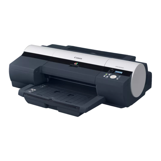
Chapter 1 1.1 Product Overview 1.1.1 Product Overview 0013-2854 This printer is capable of printing on A4- to A2-size cut sheets and its maximum print width is 17 inches. This printer is a desktop large-format printer twelve-color (dye- and pigment-based colors) printer that can be used to print office documents as well as handy POP and posters. An auto roll feed unit holder is optionally available for printing on roll media. -
Page 16: Ink Tank
Chapter 1 1.2.2 Ink Tank 0013-0608 The ink tank is disposable. There are twelve pigment-based ink colors (matte black,black,photo cyan,cyan,photo magenta,magenta,yellow,red,blue,green,gray,and photo gray). This printer features a mechanism by which only the correct color ink tank will fit in the given slot. When the message No Ink is displayed, replace the ink tank with a new one. -
Page 17: Consumables
Chapter 1 F-1-9 1.2.5 Consumables 0013-0609 Printhead The consumable print head is the same as that supplied with the printer. F-1-10 Ink Tanks The consumable ink tanks are available in twelve colors (matte black, black, photo cyan, cyan, photo magenta, magenta, yellow, red, blue, green, photo gray, and gray). -
Page 18: Product Specifications
Chapter 1 1.3 Product Specifications 1.3.1 Product Specifications 0013-0610 Type Bubble jet large-sized paper printer Feeding system Automatic feeding of one roll media (option)/Cassette paper feeding/ One cut sheet (manual feed from front)/One cut sheet (manual feed from top) Feeding capacity - Roll media (option) One roll at the back/Outer diameter of roll: 150 mm or less/Inner diameter of paper tube: 2 or 3 inches... -
Page 19: Detailed Specifications
Chapter 1 Detection functions (Paper path Detects presence/absence of paper, remaining paper, cutter position, system) presence/absence of the cassette, leading/trailing edge of paper, paper width, and skew. Operating noise During printing: Approx. 53 dB (A) or less During standby: Approx. 35 dB (A) or less Operating environment Temperature: 15 oC to 30oC Humidity: 10% to 80% without dew condensation... - Page 20 Chapter 1 Twisted-pair shielded cable, 5.0 m max. Compliant with the USB standard. Wire materials: AWG No.28, data wire pair (AWF: American Wire Gauge) AWG No.20 to No.28, power distribution wire pair (5) Interface connector Printer side: Series B receptacle compliant with USB standard Cable side: Series B plug compliant with USB standard b.
-
Page 21: Names And Functions Of Components
Chapter 1 1.5 Names and Functions of Components 1.5.1 Front 0012-6334 F-1-13 [1] Top cover Open this cover when installing the printhead or remove the paper jammed inside the printer. [2] Ink tank cover Open this cover when replacing ink tanks. [3] Cassette Load paper in this tray [4] Operation panel... -
Page 22: Carriage
Chapter 1 1.5.3 Carriage 0013-3730 F-1-15 [1] Carriage [2] Printhead lock cover This cover is used to lock the printhead. Open this cover when installing the printhead. [3] Printhead The printhead incorporated nozzles. It is an important part for printing. [4] Printhead lock lever This lever is used to lock the printhead. -
Page 23: Basic Operation
Chapter 1 1.6 Basic Operation 1.6.1 Operation Panel 0013-0043 This section explains the functions of the buttons and the meanings of the LEDs on the operation panel. Data Message Auto Feed [14] Feeder Power Online Selection [13] Stop/Eject Menu Information (1 Sec.) [12] Cleaning... -
Page 24: Printer Stats Transition
Chapter 1 This button sets or executes the selected operation or value. [12] Stop/Eject button This button aborts the job in progress and ejects the media. [13] Power button This button turns on/off the printer. [14] Color label This label indicates the ink tank colors and names that correspond to the ink level indications shown on the display. 1.6.2 Printer Stats Transition 0012-6208 The following chart shows various printer states and how they are transited by button operations. - Page 25 Chapter 1 MAIN MENU Head Cleaning *1 Head Cleaning A Head Cleaning B Force Cutting Paper Settings Cas Paper Type Cas Paper Size Tray Paper Type Roll Media Type *2 Chk Remain.Roll *3 Roll Length Set ##.# m ### feet Med.Detail Set.
- Page 26 Chapter 1 Media detail setup menu Med.Detail Set. Media type Roll DryingTime 30 sec.,1 min.,3 min.,5 min.,10 min.,30 min. 60 min. Scan Wait Time 1 sec.,3 sec.,5 sec.,7 sec. 9 sec. Feed Priority Automatic Band Joint Print Length Adjust Length -0.70% 0.00% 0.70%...
- Page 27 Chapter 1 Printing adjustment menu Adjust Printer Auto Head Adj. Advanced Adj. Standard Adj. Auto Print Manual Head Adj Auto Band Adj. Standard Adj. Advanced Adj. Manual Band Adj Adjust Band Adj Far Ed Feed Adjust Length F-1-21 1-13...
- Page 28 Chapter 1 Interface setup menu Interface Setup EOP Timer 10 sec. 30 sec.,1 min.,2 min., min., 10 min.,30 min. 60 min. TCP/IP TCP/IP IP Mode Manual Automatic Protocol DHCP BOOTP RARP IP Setting IP Address 0 255. 0 255. 0 255.0 255 Subnet Mask 0 255.
- Page 29 Chapter 1 System setup menu System Setup Warning Buzzer Ignore Mismatch Keep Media Size Sht Selection ISO A3+ ANSI B Super Roll Selection1 *1 ISO A3 (297mm) 300mm Roll Roll Selection2 *1 10in. (254mm) JIS B4 (257mm) Nozzle Check Automatic 5 pages 10 pages Sleep Timer...
- Page 30 Chapter 1 Time Zone setting menu Time Zone London (GMT) +1 Paris , Rome +2 Athens , Cairo +3 Moscow +4 Eerevan , Baku +5 Islamabad +6 Dacca +7 Bangkok +8 Hong Kong +9 Tokyo , Seoul +10 Canbera +11 NewCaledonia +12 Wellington -12 Eniwetok -11 Midway Is.
-
Page 31: Safety And Precautions
Chapter 1 1.7 Safety and Precautions 1.7.1 Safety Precautions 1.7.1.1 Moving Parts 0013-3746 Moving parts of the printer include the carriage unit driven by the carriage motor, the carriage belt, the ink tube, the flexible cable, the feed roller drives the feed motor, the pinch roller, and the purge unit driven by the purge motor. -
Page 32: Electric Parts
Chapter 1 - Although the ink is not harmful to the human body, it contains organic solvents. Ink may contaminate the surrounding parts. Carry out the work with due caution. If your hands are stained with ink, wash them with a plenty of water. Be careful not to allow the ink to get into your mouth or eyes. -
Page 33: Other Precautions
Chapter 1 1.7.2 Other Precautions 1.7.2.1 Printhead 0013-1929 1. How to Handle the Printhead Do not open the printhead package until you are ready to install the head. When installing the printhead in the printer, hold the knob[1] and then remove the protective cap 1[2] and protective cap 2[3] in that order. Do not reattach the protective cap 2[3] to the printhead because the cap may damage the nozzles[4]. -
Page 34: Ink Tank
Chapter 1 1.7.2.2 Ink Tank 0013-1924 1. Unpacking the Ink Tank Do not unpack the ink tank until you are ready to install it. When installing the ink tank, be sure to shake it slowly 7 to 8 times before unpacking it. Otherwise, the ink ingredients may precipitate and degrade the print quality. To prevent foreign matter from entering the ink port, installed the unpacked ink tank in the printer immediately. - Page 35 Chapter 1 F-1-32 2. Fixing the Carriage After completion of printing, the carriage is mechanically locked by the lock arm in the purge unit at the same moment the printhead is capped. Before transporting the printer, secure the carriage at its home position using belt stoppers[1] so that the carriage does not become separated from the lock arm and damage or ink does not leak.
-
Page 36: Precautions When Servicing Printer
Chapter 1 1.7.3 Precautions When Servicing Printer 1.7.3.1 Notes on the Data Stored in the Printer 0013-3742 This printer counts the print length, number of ink tank replacements, carriage driving time, number of cleaning operations, number of cutter operations, and so on and stores them in the main controller's EEPROM as a service mode counter. -
Page 37: Chapter 2 Technical Reference
Chapter 2 TECHNICAL REFERENCE... - Page 39 Contents Contents 2.1 Basic Operation Outline ..............................2-1 2.1.1 Printer Diagram .................................... 2-1 2.1.2 Print Driving....................................2-2 2.2 Firmware..................................2-2 2.2.1 Operation Sequence at Power-on ..............................2-2 2.2.2 Operation Sequence at Power-off ..............................2-2 2.2.3 Print Control....................................2-3 2.2.4 Print Position Adjustment Function ............................. 2-4 2.2.5 Head Management..................................
- Page 40 Contents 2.4 Printer Electrical System..............................2-30 2.4.1 Outline......................................2-30 2.4.1.1 Overview........................................2-30 2.4.2 Main Controller ..................................2-31 2.4.2.1 Main controller components ..................................2-31 2.4.3 Carriage Relay PCB ................................... 2-33 2.4.3.1 Carriage PCB components.................................... 2-33 2.4.4 Motor Driver ....................................2-33 2.4.4.1 Cutter driver PCB components..................................2-33 2.4.4.2 Roll feed unit PCB components ...................................
-
Page 41: Basic Operation Outline
Chapter 2 2.1 Basic Operation Outline 2.1.1 Printer Diagram 0013-4117 Shown below is a printer diagram. Operation Panel J2601 Carriage Unit Carriage Motor Multi Sensor Feed Motor Linear Encoder Suction Fan Maintenance Cartridge Relay PCB Option Maintenance Cartridge Cassette Paper Detection Sensor Roll Cam Sensor Feed Roller HP Sensor Roll Motor... -
Page 42: Print Driving
Chapter 2 2.1.2 Print Driving 0013-5168 During printing, print signals and control signals are issued to the printhead via the carriage PCB in order to discharge ink from the nozzles. On a printhead, six arrays of nozzles are provided in six arrays in a staggered pattern. This printer uses a pair of printheads. -
Page 43: Print Control
Chapter 2 case, the printer may stop without capping the print head. If the power was turned on by unplugging the power cord, plug the power cord into the outlet, turn on the power again so that the printer enters the online state, and then press the Power button to turn off the power. Hold down for at least once second Power button OFF If media remains,it is ejected even... -
Page 44: Print Position Adjustment Function
Chapter 2 Media Type Print Priority Print Quality Print-pass Printing direction(*1) Print resolution Glossy Photo Paper Image Standard 6-pass Bi-directional 1200x1200dpi Semi-Glossy Photo Paper High 8-pass Bi-directional 2400x1200dpi Heavyweight Glossy Photo Paper Highest Heavyweight SemiGlos Photo Paper Glossy Paper Photo Paper Plus Photo Paper Plus Semi-Glos Synthetic Paper Adhesive Synthetic Paper... - Page 45 Chapter 2 or offline mode. The printer wakes from the Sleep mode when the user presses any button on the operation panel or data is received from the host computer. The time until the printer enters the Sleep mode can be changed from the operation panel. (Default: 15 minutes)
-
Page 46: Printer Mechanical System
Chapter 2 2.3 Printer Mechanical System 2.3.1 Outline 2.3.1.1 Outline 0013-4298 The printer mechanism can be broadly divided into two major components: the ink passage and paper path. The ink passage consists of an ink tank, a carriage unit having a printhead, a purge unit. and a maintenance cartridge unit which are used to supply, circulate, and suck ink. -
Page 47: Ink Tank Unit
Chapter 2 Mechanical Drive Unit Ink or air flow Carriage unit Joint Ink tank Printhead Agitation plate Suction pump Sub buffer Ink supply valve Maintenance cartridge Absorbent material under the purge unit F-2-5 a) Ink supply from ink tank to ink supply valve The ink tank contains ink to be supplied to the printhead. - Page 48 Chapter 2 When the ink tank lever of the printer is pressed down, the hollow needle enters the air passage (covered with a rubber plug) and thus the internal pressure of the ink tank is released, maintaining the internal pressure constant. d) Notches for preventing incorrect insertion The ink tanks have notches for preventing insertion.
-
Page 49: Carriage Unit
Chapter 2 Valve cam Valve motor Linkage Valve open/closed detection sensor Linkage Ink supply valve F-2-7 2.3.2.3 Carriage Unit 2.3.2.3.1 Functions of Carriage Unit 0013-4306 a) Printhead mounting function The carriage mechanically locks the printhead and is connected to the printhead via the terminals on the carriage PCB. b) Control function The carriage incorporates a carriage PCB that relays the signal from the main controller, a linear encoder that generates a print timing signal based on the detected carriage position, and a multi sensor that detects the media width and skewing to adjust the registration and height. -
Page 50: Structure Of Carriage Unit
Chapter 2 Semi-glossy canvas(0.5) Board paper(1.5) g) Paper leading edge detection function/paper width detection function/skewing detection function The leading edge, width, and skewing of the paper fed to the platen is detected by the multi sensor mounted at the lower left of the carriage. h) Auto print head position adjustment function The adjustment pattern printed on paper is read by the multi sensor mounted at the lower left of the carriage, thus adjusting the printing timings of each printhead automatically. - Page 51 Chapter 2 Linear encoder Carriage PCB Shaft cleaner Multi sensor Shaft cleaner Multi sensor reference plate Linear scale Carriage height changing cam Head management sensor unit Lift cam sensor Lift motor F-2-9 e) Printhead maintenance unit The printer performs the printhead cleaning operation at the home position of the carriage. The purge motor is used for wiping.
-
Page 52: Printhead
Chapter 2 2.3.2.4 Printhead 2.3.2.4.1 Structure of Printhead 0013-4821 A printhead incorporates six nozzle arrays. Each nozzle can be controlled individually so that a six-color discharge action can be performed by a single printhead. a) Nozzle arrays A total of 2560 nozzles are arranged in a two-column staggered pattern. In each column, 1280 nozzles are arranged in a staggered pattern at intervals of 600 dpi, forming a 2560-nozzle arranged at intervals of 1200 dpi. - Page 53 Chapter 2 - Wiping operation This operation is performed to remove paper fibers and dried ink from to the face plate. - Pumping operation This operation is performed to remove ink from the nozzles and fill the nozzles with fresh ink. - Maintenance jet operation This operation is performed to spray ink from the nozzles to the cap, borderless ink jet tray, an paper to remove bubbles in the nozzles and dust and other foreign particles.
-
Page 54: Structure Of Purge Unit
Chapter 2 Printer status Description of cleaning During printing Between scan operations during Idle ejection + Wiping (idle suction) scanning After printing After printing exceeding the prescribed Cleaning 16 (dot count suction) based on the count dot count or cleaning 6 (normal (strong) cleaning) Each time 120 minutes have elapsed in Cleaning 1 (normal cleaning) the cap open status... - Page 55 Chapter 2 Carriage lockpin Pump cam sensor Glycerin tank Sub cap Purge motor Pump encoder F-2-13 b) Wiper unit The wiper unit operated by the purge motor wipes the print head face. The printer is provided with a pair of wiper blades for better wiping performance. The wiping operation is performed by a "slide wipe"...
-
Page 56: Maintenance Cartridge
Chapter 2 Pump unit Pump cam sensor Suction pump Push rollers Ink tubes Purge motor Sub cap Pump encoder To maintenance cartridge. The ink from the sub cap flows to the absorbent material under the purge unit. F-2-15 2.3.2.6 Maintenance Cartridge 2.3.2.6.1 Maintenance cartridge 0013-4161 a) Maintenance cartridge... -
Page 57: Paper Path
Chapter 2 Fan filter Mist fan F-2-17 During operation of the suction fan, suspended substances are collected in the filter through the airflow path inside the printer, preventing them from being emitted to outside of the printer. Fan filter Suction fan F-2-18 2.3.3 Paper Path 2.3.3.1 Outline... -
Page 58: Paper Path
Chapter 2 Manually fed cut sheet (top) Paper deteciton sensor Multi sensor Roll media Feed roller Roll media sensor Flapper Cassette feed roller Manually fed cut sheet (front) Cassette pickup roller Paper return guide Cassette pick-up Cassette paper sensor Cassette feed roller 1 Cassette paper Pressure Separation roller... - Page 59 Chapter 2 Cassette unit Paper detection sensor F-2-20 2-19...
- Page 60 Chapter 2 Cassette pick-up sensor F-2-21 The cassette pick-up roller and cassette feed roller are driven by the cassette motor under the control of the cassette encoder. cassette motor cassette encoder F-2-22 At the bottom of the cassette unit are mounted a cassette detection sensor and a cassette paper detection sensor to check whether a cassette is loaded and whether paper is present in the cassette.
- Page 61 Chapter 2 cassette detection sensor cassette paper detection sensor F-2-23 cassette cam sensor F-2-24 2-21...
-
Page 62: Cassette Pick-Up Sequence
Chapter 2 Holding plate cassette cam sensor F-2-25 2.3.3.2.2 Cassette Pick-up Sequence 0013-4172 When a Print command is received with paper loaded in the cassette, cassette pick-up operation starts. The paper supplied from the cassette is checked for normal feeding using the sensors provided along the paper feed path. When the paper is fed by the specified length, the multi sensor adjusts the light intensity and the head hight, detects the paper width, and then starts printing. -
Page 63: Roll Media Pick-Up Sequence
Chapter 2 roll cam sensor roll feed unit PCB roll motor F-2-27 If the roll media sensor detects that there is no roll during roll media pick-up operation, the roll media is ejected. Auto Roll Feed Unit roll media sensor F-2-28 2.3.3.2.4 Roll Media Pick-up Sequence 0013-4173... -
Page 64: Structure Of The Manual Feed Unit
Chapter 2 Roll media loading (manual) Roll media detection (roll media sensor) Light intensity/ Head hight adjustment Detection of leading edge of media *2 Detection of bar code pattern *1 Detection of skewed media Media width detection Detection of leading edge of media *2 End of roll media pick-up Printing - This operation is performed only when "ON"... - Page 65 Chapter 2 menu, the pinch roller unit moves up to allow you to feed paper from the front of the printer according to the message shown on the operation panel. The pinch roller unit is moved up and down by the lift motor. The cam which is also operated by the lift motor via gears moves up and down the pinch roller. carriage height changing cam lift cam...
-
Page 66: Manual Feed (From Front) Sequence
Chapter 2 paper detection sensor F-2-33 2.3.3.2.6 Manual Feed (from Front) Sequence 0013-4174 This sequence can be performed according to the messages shown on the operation panel only when a specific type of media is selected after selecting the manual feed mode from the menu shown on the operation panel. -
Page 67: Structure Of Feed Roller Unit
Chapter 2 Cut sheet loading (manual) Detection of cut sheet *1 Light intensity/ Head hight adjustment Detection of paper width Detection of skewed movement of paper End of cut sheet pick-up operation Printing The auto roll feed unit starts feeding the cut sheet when the roll media detection sensor detects the media. When the auto roll feed unit is not mounted, the printer starts feeding the media when the paper detection sensor detects the media. -
Page 68: Feed Roller Eccentricity Detection Function
Chapter 2 2.3.3.2.9 Feed Roller Eccentricity Detection Function 0013-4206 Media are fed by the feed roller at regular intervals. Irregular feeding of media due to the feed roller eccentricity problem, irregular printing can occur in the media feeding direction periodically. To prevent this, the feed error encoder and feed roller HP sensor detect the presence and amount of feed roller eccentricity every rotation of the feed roller. -
Page 69: Cutter Unit
Chapter 2 feed roller shaft eject roller shaft drive belt spur cam sensor spur motor spur unit F-2-39 2.3.3.3 Cutter Unit 2.3.3.3.1 Structure of the cutter unit 0013-4209 When "Auto cut: Yes" is selected in the printer driver when roll media is used, the cutter unit mounted in front of the spur unit automatically cuts the roll media. The cutter unit is moved up and down by the cutter lift motor. -
Page 70: Printer Electrical System
Chapter 2 cutter cutter lift motor cutter right cutter motor position sensor cutter lift sensor cutter HP sensor F-2-40 2.4 Printer Electrical System 2.4.1 Outline 2.4.1.1 Overview 0013-4304 The printer electrical system consists of the main controller PCB and power supply PCB which are mounted on the left side of the printer, the cutter driver PCB, the carriage PCB and print head which are mounted in the carriage, and other electrical components such as the operation panel, sensors, and motors. -
Page 71: Main Controller
Chapter 2 Operation Host computer panel Interface Operation panel control function control function Carriage PCB Image data control function Printhead Maintenance cartridge DI sensor reading relay PCB control function EEPROM control function Carriage position Linear sensor control function Remaining ink level detection function Multi sensor Ink tank unit... - Page 72 Chapter 2 This unit converts the RGB multi-value image data or CMYK multi-value data received from the host computer through the interface connector to the binary image data for the ink colors used. DMA controller This controller control DMA transfer of the data transferred through the input interfaces such as the USB and expansion card slot as well as DMA transfer of the data stored in the DIMM.
-
Page 73: Carriage Relay Pcb
Chapter 2 MEMO: After replacement of the main controller PCB, the printer must be started up in the service mode to take over the setting and adjustment values to the new PCB properly (the service mode will be switched to the PCB replacement mode automatically). 2.4.3 Carriage Relay PCB 2.4.3.1 Carriage PCB components 0013-4310... -
Page 74: Maintenance Cartridge Relay Pcb
Chapter 2 Roll motor drive function This function controls the roll motor based on the control signals from the main controller. Sensor relay function This function relays the input signals from the roll cam sensor and roll media sensor to the main controller PCB. 2.4.5 Maintenance Cartridge Relay PCB 2.4.5.1 Maintenance cartridge relay PCB components 0013-5143... -
Page 75: Detection Functions With Sensors
Chapter 2 2.5 Detection Functions with Sensors 2.5.1 Sensors for covers 0013-4305 Top cover sensor Ink tank cover switch F-2-48 Top cover sensor The photo-interrupter-type top cover sensors detect opening and closing of the top cover. When the top cover is closed, the sensor light is shielded by the sensor arm, thus notifying the sensor of closing the cover. Ink tank cover switch The micro-switch-type ink tank cover switch detects opening and closing of the ink tank cover. -
Page 76: Ink Passage System
Chapter 2 2.5.2 Ink passage system 0013-4334 Purge unit Pump cam sensor Valve open/closed detection sensor Pump encoder Head management sensor F-2-49 Pump cam sensor The photo-interrupter-type pump cam sensor detects that the sensor light is shielded or unshielded by the rotary cam. The sensor detects the purge unit capping and wiping states with the combination of the state detected by the pump cam and the state of pump motor rotation control performed by the pump encoder. - Page 77 Chapter 2 Slits Sensor F-2-51 Valve open/closed detection sensor The photo-interrupter-type valve open/closed detection sensor detects the valve cam state. When the link that operates in conjunction with the valve cam shields light, this sensor detects that the ink supply valve has been opened. Ink detection sensor Presence of absence of ink in the ink tank is detected according to whether the two hollow needles are electrically connected.
-
Page 78: Carriage System
Chapter 2 2.5.3 Carriage system 0013-4338 Linear encoder Multi sensor Lift cam sensor F-2-54 Multi sensor The photo-reflection-type multi sensor is composed of four LEDs (red, blue, green and infrared) and two light-sensitive sensors. It detects the leading edge, skewing, and width of media and is used for adjustment of the registration, head height, and calibration. - Page 79 Chapter 2 The detected head temperature is used to control the head operation and to detect abnormal head temperatures. Printhead contact detection The printhead contact status is detected by testing the electrical conductivity. It is detected according to the voltage changes at the two terminals of the contact faces, power supply terminals, and GND terminal. 2-39...
-
Page 80: Paper Path System
Chapter 2 2.5.4 Paper path system 0013-4339 Spur cam sensor Cassette cam sensor Paper detection sensor Cassette pick-up sensor Cassette encoder Cutter lift sensor Cutter HP sensor Cutter right position sensor F-2-56 Cassette pick-up sensor This is a photo-interrupter-type sensor. When paper supplied from the cassette, the sensor light is blocked by the sensor arm, thus detecting paper. Cassette cam sensor 2-40... - Page 81 Chapter 2 This is a photo-interrupter-type sensor. When the cassette camp rotates to block the sensor light, lowering of the pressure plate of the cassette is detected. Cassette encoder The cassette encoder detects the slits on the encoder film during cassette motor rotation, thus detecting the amount of rotation of the roller. Paper detection sensor This is a photo-interrupter-type sensor.
-
Page 82: Others
Chapter 2 The feed roller HP sensor detects the change from the white portion (unshielded sensor light) to black portion (shielded sensor light) of the encoder film on the feed roller, thus setting the home position for feed roller eccentricity compensation. Feed roller encoder The feed roller encoder detects the slits on the encoder film of the feed roller during feed motor rotation, thus detecting the amount of rotation of the feed roller (media feed amount). - Page 83 Chapter 2 ink evaporation amount calculation, and suction fan control. 2-43...
-
Page 85: Installation
Chapter 3 INSTALLATION... - Page 87 Contents Contents 3.1 Installation ..................................3-1 3.1.1 Making Pre-Checks ..................................3-1 3.1.1.1 Making Pre-Checks......................................3-1 3.1.2 Unpacking and Installation................................3-1 3.1.2.1 Unpacking and Installation .....................................3-1 3.1.3 Checking the Images/Operations ..............................3-7 3.1.3.1 Checking the Images /Operations ...................................3-7 3.2 Transporting the Printer..............................3-8 3.2.1 Transporting the Printer ................................
-
Page 89: Making Pre-Checks
Chapter 3 3.1 Installation 3.1.1 Making Pre-Checks 3.1.1.1 Making Pre-Checks 0013-4023 Carry out the installation work with reference to the "Quick Start Guide" supplied with the printer. Package dimensions and weight are as follows. Main body (with a palette): 1140(W) mm x 874(D) mm x 628(H) mm, Approx. 65 kg F-3-1 Installation space Main body only: 1299(W) mm x 1833(D) mm x 617(H) mm... - Page 90 Chapter 3 (1) Check to see that none of the accessories is missing. [10] [11] [12] F-3-4 T-3-1 Main body Power Cord Paper Tray Unit Printhead Auto Roll Feed Unit(option) Ink Tank Roll Holder Set(option) [10] Cleaning Brash Output Tray [11] Reference guides Cassette [12] CD-ROM...
- Page 91 Chapter 3 (3) Grasaping the carrying handles[1] on the left and right side of the bottom,place the printer on a level place such as a table. F-3-6 (4) Remove all cushioning materials and tape from the printer and accessories. F-3-7 (5) Install the IEEE1394 Board(option).
- Page 92 Chapter 3 F-3-11 (10) When the message "Open Top Cover"is displayed,open the top cover. F-3-12 (11) Pull the printhead fixer lever forward to open it fully. F-3-13 (12) Raise the printhead fixer cover to open it fully. F-3-14 (13) Holding the knobs[1],take out the printhead from the case. F-3-15 - Do not touch the nozzles[2] and contacts[3] on the printhead[1].
- Page 93 Chapter 3 F-3-17 (15) Insert the print head in the carriage with the nozzles down and the contacts in the back. Insert it as far as it will go while taking care that the nozzles and contacts do not touch the carriage. F-3-18 (16) Turn the printhead fixer cover forward to lock the printhead.
- Page 94 Chapter 3 (21) Press the stopper at the top the ink tank lock lever,and then open the ink tank lock lever upward. F-3-23 (22) Before unpacking the ink tank you want to install,shake it slowly 7-8 times. F-3-24 (23) Open the package and take out the ink tank by holding its knobs. F-3-25 - Never touch the ink port[1] and contacts[2].
-
Page 95: Checking The Images/Operations
Chapter 3 F-3-27 (25) close the ink tank lock lever until it clicks. F-3-28 (26) Check that the Ink lamp is light in red. F-3-29 (27) Repeat steps(21)to(25)to install all ink tanks. (28) Close the ink tank cover. F-3-30 (29) When the printhead and all ink tanks have been installed,the message "Do Not Open Cover" appears on the display and initial ink filling requires about 10 minutes. -
Page 96: Transporting The Printer
Chapter 3 3.2 Transporting the Printer 3.2.1 Transporting the Printer 3.2.1.1 Transporting the Printer 0013-4205 When transporting the printer, the printhead must be capped and stay in the carriage. In spite of this precaution, shocks incurred during transportation can damage the printhead. Print the nozzle check pattern before making preparations for transporting the printer, pint the nozzle check pattern again after installing the printer at the new location, and then compare the two printouts. -
Page 97: Reinstalling The Printer
Chapter 3 3.2.2 Reinstalling the Printer 3.2.2.1 Reinstalling the Printer 0013-4210 When installing the printer after moving it on the same floor having no step If you have moved the printer to the installation site on the same floor having no step without draining ink, check the operation test pattern. When installing the printer after moving it on the same floor having a step(s) If you have moved the printer to the installation site on the same floor having a step(s) with ink drained, install it again in the same manner as that for initial installation after reception of the delivered printer. - Page 99 Chapter 4 DISASSEMBLY/REASSEMBLY...
- Page 101 Contents Contents 4.1 Service Parts .................................. 4-1 4.1.1 Service Parts....................................4-1 4.2 Disassembly/Reassembly .............................. 4-1 4.2.1 Disassembly/Reassembly ................................4-1 4.3 Points to Note on Disassembly and Reassembly ......................4-3 4.3.1 Note on assemblies (or units) prohibited from disassembly ......................4-3 4.3.2 Moving the carriage manually..............................
-
Page 103: Chapter 4 Disassembly/Reassembly
Chapter 4 4.1 Service Parts 4.1.1 Service Parts 0012-6347 The service parts indicated below require careful handling. 1. Keep all packages with the warning not to turn over. Pay careful attention to all individually packaged service part (carriage unit, purge unit, ink tank unit, and other parts) boxes marked "This side up" and handle appropriately. - Page 104 Chapter 4 Printer Move carriage onto platen Open top cover Purge unit Output tray unit Left/right circle cover Right upper cover Operation panel Mist filter Filter cover Lower rear cover Right cover Right front cover Mist fan F-4-3 3) Cutter unit disassembly flow <Meanings of symbols>...
-
Page 105: Points To Note On Disassembly And Reassembly
Chapter 4 Printer Right cover Automatic ink draining Upper front cover Open top cover Lower front cover Output tray unit Manual ink draining Move carriage onto platen Left/right circle cover Ink tube holder Tank cover Joint base Left cover Cutter unit Left front cover Right upper cover Cutter lifter unit... -
Page 106: External Covers
Chapter 4 F-4-7 4.3.4 External Covers 0012-6358 a) Left/right circle cover Removing the left/right circle cover 1) When removing the left circle cover [1], turn it in the direction of the arrow. F-4-8 2) When removing the right circle cover [1], turn it in the direction of the arrow. F-4-9 Attaching the left/right circle cover 1) When attacing the left circle cover, fit it in place with the three hooks [1] up and turn it toward the rear side of the printer. - Page 107 Chapter 4 F-4-10 b) Tank cover Removing the left cover 1) When removing the tank cover[4], remove the left circle cover and then open the top cover. 2) Open the tank cover, remove the three screws[1], and then release the three hooks[2] while opening the hook[3] outward. F-4-11 c) Left cover Removing the left cover...
- Page 108 Chapter 4 F-4-12 d) Lower rear cover Removing the lower rear cover 1) When removing the lower rear cover[2], remove the two screws[1] and then remove it. F-4-13 e) Left rear cover Removing the left rear cover 1) When removing the left rear cover[2],open the top cover, and then remove the left circle cover, tank cover, and left rear cover. 2) Remove the three screws[1], and then remove the left rear cover[2].
- Page 109 Chapter 4 F-4-15 g) Right upper cover Removing the right upper cover 1) When removing the right upper cover[2], open the top cover, and then remove the right circle cover. 2) Release the two hooks[1], and then remove the right upper cover[2]. F-4-16 h) Operation panel Removing the operation panel...
- Page 110 Chapter 4 F-4-18 j) Mist filter Removing the mist filter 1) When removing the mist filter[2], open the top cover,and then remove the right circle. 2) Removing the screw[1], and then remove the mist filter[2]. F-4-19 k) Right cover Removing the right cover 1) When removing the right cover[2], open the top cover, and then remove the right circle cover, right upper cover, operation panel, mist filter, filter cover, filter, and lower rear cover.
- Page 111 Chapter 4 F-4-21 m) Upper rear cover Removing the upper rear cover 1) When removing the upper rear cover[2], open the top cover,left circle cover, tank cover, right circle cover, right upper cover, operation panel, mist filter, filter cover, filter, right cover, and rear lower cover. 2) Remove the three screws[1], and then remove the upper rear cover[2].
- Page 112 Chapter 4 F-4-24 p) Rear cover Removing the rear cover 1) When removing the rear cover[2], open the top cover, left circle cover, tank cover, left cover, left rear cover, right circle cover, right upper cover, operation panel, mist filter, filter cover, filter, right cover, and lower rear cover. 2) Remove the three screws[1],and then remove the rear cover[2].
-
Page 113: Driving Unit
Chapter 4 F-4-27 s) Cover support plate (right) Removing cover support plate (right) 1) When removing the cover support plate(right)[2], open the top cover, left circle cover, tank cover, right circle cover, right upper cover, operation panel, mist filter, filter cover, filter, right cover, lower rear cover, cover guide, and upper rear cover. 2) Remove the three screws[1], and then remove the cover support plate(right)[2]. -
Page 114: Cutter
Chapter 4 F-4-30 Mounting the feed motor When mounting the feed motor, attach the timing belt[3] on the pulley, and then tighten the two screws[2]. b) Procedure after replacing the feed roller HP sensor or feed roller encoder Feed roller eccentricity is Factory-adjusted(correction of variation in the paper feed amount per rotation). It is necessary to adjust feed roller eccentricity after re- placing the feed roller HP sensor or feed roller encoder. -
Page 115: Carriage Unit
Chapter 4 F-4-33 b) Removing the cutter lifter unit 1) When removing the cutter lifter unit, open the top cover, and then remove the cassette, output tray unit, left and right circle covers, tank cover, lower rear cover, left and right covers, right upper cover, operation panel, left and right front cover, upper front cover, mist filter, filter cover, filter, and lower front cover. Refer to DISASSEMBLY/REASEMBLY >... - Page 116 Chapter 4 F-4-36 5) Remove the linear scale[1] from the right clamp plate's spring, and then remove it rightward. F-4-37 When removing the linear scale, take care not to damage or stain it. The stained or damaged liner plate can cause malfunction. 6) While sliding the pulley[2] to the left, remove the carriage belt.
- Page 117 Chapter 4 F-4-40 9) Turn the gear [1] so that the sensor flag of the lift gear [2] leaves the interrupt position of the lift cam sensor [3], then remove the ring [4], the lift gear [2] and the lift cam [5]. Disconnect the connector [6], remove the two screws [7], and then remove the lift cam sensor [3]. Remove the two torsion springs [8], pull out the carriage rail [9] from the right side of the printer, and then remove the carriage.
- Page 118 Chapter 4 F-4-43 c) Multi Sensor Recalibration Since multi sensors have individual electrical specificity, the following are recalibrated at the factory, namely, the optical axis of the sensor, the sensor gain for measuring the printhead height and color reproduction. Accordingly, carry out the following adjustments in the service mode whenever replacing the carriage unit or multi sensor.
- Page 119 Chapter 4 F-4-44 (3) Place the scale[5] on the mist fan as shown below, adjust the wire guide height so that the wire roller[6] touches the top surface of the scale, and then tighten the screw loosened in step (1). F-4-45 * To prevent the wire roller from being disengaged, install the right cover with the carriage moved onto the platen.
-
Page 120: Feeder Unit
Chapter 4 4.3.8 Feeder Unit 0012-6390 a) Removing the pinch roller 1) Removethe back cover. 2) When removing the pinch roller, press down the pinch roller unit[1] in the direction of the arrow. F-4-46 3) Remove the pinch roller[1]. F-4-47 b) Removing the cassette pick-up roller 1) When removing the cassette pick-up roller, first remove the back cover and cassette. - Page 121 Chapter 4 F-4-49 d) Removing the cassette separation roller 1) When removing the cassette separation roller, first open the top cover,and then remove the back cover, left and right covers, tank cover, right upper cover, oper- ation panel mist filter, filter cover, filter, left and right covers, lower rear cover, and lower back cover. 2) Remove the cassette pick-up sensor[3] by removing the screw[1] and connector[2].
- Page 122 Chapter 4 F-4-53 6) Remove the bearing[1] and ring[3], and then remove the separation roller shaft[2]. F-4-54 7) Remove the lever[1] while turning it in the direction of the arrow. F-4-55 8) Remove the two springs[1], and then remove the cassette separation roller[2]. F-4-56 e) Precaution for mounting the cassette separation roller 1) Align the mark on the gear[1] with the mark on the gear[2].
- Page 123 Chapter 4 F-4-57 f) Removing the spur unit 1) When removing the spur unit, first open the top cover, and then remove the left and right circle covers, tank cover, right upper cover, operation panel, lower rear cover, right cover, right front cover, upper front cover, lower front cover, cover guide, upper rear cover, and left and right cover mounting plates. Refer to DISAS- SEMBLY/REASSEMBLY >...
-
Page 124: Roll Feed Unit
Chapter 4 F-4-60 5) Turn the pulley[1] in the direction of the arrow so that the spur unit[2] is at the top position. F-4-61 6) While pressing down the protrusion[A], slide the spur unit[1] in the direction of the arrow to remove it. F-4-62 g) Handling the Feed Roller The feed roller is an important mechanical component of the printer. - Page 125 Chapter 4 F-4-63 2) Remove the four screws[1], and then remove the left cover[2] and paper tray[3]. F-4-64 3) Remove the three screws[1], andthen remove the right inner cover[2]. F-4-65 4) Remove the two screws[1], and then remove the roll motor[2]. 4-23...
- Page 126 Chapter 4 F-4-66 b) Removing the roll feed unit 1) When removing the roll motor, remove the roll feed unit[2] from the main body, and then remove the right cover[3] by removing the two screws[1]. F-4-67 2) Remove the four screws[1], and then remove the left cover[2] and paper tray[3]. F-4-68 3) Remove the three screws[1], andthen remove the right inner cover[2].
-
Page 127: Purge Unit
Chapter 4 F-4-69 4) Remove the two screws[1], and then remove the roll feed unit PCB[2]. F-4-70 4.3.10 Purge Unit 0012-6392 a) Removing the purge unit 1) Turn the gear[1] of the purge unit[3] in the direction of the arrow to unlock and uncap the carriage. Next, move the carriage[2] onto the platen. F-4-71 2) Disconnect the connector[1], and then remove the harness from the harness guide. -
Page 128: Waste Ink Collection Unit
Chapter 4 F-4-72 3) Remove the three screws[3], remove the waste ink tube joint[1] by turning it in the direction of the arrow, and then remove the purge unit[2]. F-4-73 b) Precaution for mounting the purge unit When mounting the purge unit, pull out the waste ink tube[1] from the back of the printer to the position where the marking is visible. It the waste ink tube is not pulled out to the marking position, it may bend and cause ink leakage. - Page 129 Chapter 4 F-4-75 3) Disconnect the connector[2], and then remove the waste ink box[1]. F-4-76 b) Removing the mist fan 1) When removing the mist fan, first open the top cover, and then remove the output tray, right circle cover, right upper cover, operation panel, mist filter, filter cover, filter, right cover, and right front cover.
- Page 130 Chapter 4 F-4-78 3) Remove the front duct[2] by removing the four screws[1]. F-4-79 4) Remove the platen(front)[2] by removing the four screws[1]. F-4-80 5) Remove the three screws[1]. 4-28...
-
Page 131: Ink Tank Unit
Chapter 4 F-4-81 6) Disconnect the two waste ink tubes[3], and then remove the platen duct[2] by removing the five screws[1] and five bushings[4]. F-4-82 4.3.12 Ink Tank Unit 0012-6397 a) Removing the ink tank unit 1) Drain the ink. Refer to DISASSEMBLY/REASSEMBLY > Points to Note on Disassembly and Reassembly > Draining the ink. 2) Remove the output tray, left and right circle covers, tank cover, left and right covers, left and right front covers, right upper cover, operation panel, mist filter, filter cover, filter, lower rear cover, upper front cover, and lower front cover. - Page 132 Chapter 4 F-4-84 Put the removed joint base in a plastic bag so that ink does not splash. F-4-85 6) Remove the cutter unit and cutter lifter unit. Refer to DISASSEMBLY/REASSEMBLY > Point to Note on Disassembly and Reassembly > Cutter 7) Remove the two screws[1], and then remove the support plate[2].
-
Page 133: Head Management Sensor
Chapter 4 F-4-87 9) Remove the four screws[1] and one joint[3], and then remove the two ink tank unit F[2]. F-4-88 b) Removing the valve motor unit. 1) When removing the valve motor unit, remove the ink tank cover. 2) Remove the two screws[1], disconnect the the two connectors[2], and then remove the valve motor unit[3]. F-4-89 4.3.13 Head Management Sensor 0013-3845... -
Page 134: Multi Sensor
Chapter 4 F-4-90 b) Procedure after replacing the head management sensor Since the distance between the head management sensor and the carriage unit varies among printers, the optical axis is factory-adjusted to adjust the non-discharging detection position. When you have replaced the head management sensor or performed assembly/reassembly of surrounding parts that can change the distance be- tween the head management sensor and the carriage unit, reasjustment is required. -
Page 135: Pcbs
Chapter 4 4.3.15 PCBs 0012-6407 Do not replace the main controller PCB and maintenance cartridge relay PCB(ROM board) at the same time. These PCBs store important data such as settings and carriage drive time. Before replacement of enther PCB, the data stored in it is move to the other PCB through internal communication so that it can be taken over to the new PCB automatically. -
Page 136: Opening/Closing The Ink Supply Valve
Chapter 4 F-4-93 4.3.17 Opening/Closing the Ink Supply Valve 0012-6413 1) Open the top cover, and then remove the left circle cover tank cover. 2) To open the ink supply valve, turn the cam[2] in the direction of the arrow and press the link[1]. F-4-94 * If the tube is full of ink, releasing the printhead lock lever with the ink supply valve open can cause the ink to flow back to the ink supply unit, resulting in leakage of ink from the ink supply needle. -
Page 137: Applying The Grease
Chapter 4 F-4-95 4) Release both printhead fixer levers[1] to flow the ink from inside the ink tube to the sub-buffer of the ink tank unit. F-4-96 The sub-buffer can contain 22g of ink. About 6g of ink flows into the sub-buffer each time manual ink drainage is performed. Make sure that the ink has been drained completely, turn the cam to close the ink supply valve. - Page 138 Chapter 4 PG 641 Approx.12mg PG 641 Approx.6mg F-4-97 2) Wire roller PG 641 Approx.5mg PG 641 Approx.5mg F-4-98 3) Slide roller 4-36...
- Page 139 Chapter 4 PG 641 Approx.20mg F-4-99 b) Eject roller unit 4) Eject roller bearing 5) Eject roller center bearing PG 641 Approx.12mg PG 641 Approx.12mg iPF500/5000 and two locations on iPF600 PG 641 Approx.12mg F-4-100 c) Spur unit 6) Spur cam 4-37...
-
Page 140: Adjustment And Setup Items
Chapter 4 PG 641 Approx.20mg F-4-101 d) Pick-up unit 7) Pick-up cam PG-641 Approx.12mg F-4-102 4.5 Adjustment and Setup Items 4.5.1 Procedure after Replacing the Feed Roller HP Sensor or Feed Roller Encoder 0012-6480 Procedure after replacing the feed roller HP sensor or feed roller encoder Feed roller eccentricity is factory-adjusted (correction of variation in the paper feed amount per rotation). - Page 141 Chapter 4 * Make adjustments with the carriage lock released. * Make adjustments with the tube disconnected from the tube guide. (1) Loosen the two screws[1] (2) Turn the gear[2] until the lift cam flag[3] reaches the position shown below. * Bottom position where the sensor[4] light is blocked by the flag (lowest position to which the carriage unit descends) F-4-103 (3) Place the scale[5] on the mist fan as shown below, adjust the wire guide height so that the wire roller[6] touches the top surface of the scale, and then tighten...
-
Page 142: Procedure After Replacing The Head Management Sensor
Chapter 4 * After installing the right cover, check that the wire roller has not been disengaged. 4.5.3 Procedure after Replacing the Head Management Sensor 0012-6487 Since the distance between the head management sensor and the carriage unit varies among printers, the optical axis is factory-adjusted to adjust the non-discharging detection position. -
Page 143: Chapter 5 Maintenance
Chapter 5 MAINTENANCE... - Page 145 Contents Contents 5.1 Periodic Replacement Parts ............................5-1 5.1.1 Periodic Replacement Parts................................5-1 5.2 Consumable Parts ................................5-1 5.2.1 Consumable Parts..................................5-1 5.3 Periodic Maintenance ..............................5-1 5.3.1 Periodic Maintenance................................... 5-1...
-
Page 147: Periodic Replacement Parts
Chapter 5 5.1 Periodic Replacement Parts 5.1.1 Periodic Replacement Parts 0013-4084 T-5-1 Level Periodic Replacement part User None Service None Personnel 5.2 Consumable Parts 5.2.1 Consumable Parts 0013-4086 T-5-2 Level Consumable Durability Remarks Part name Part No, User See 1.2.6 "Consumable" Service FAN UNIT, SUCTION QM3-0179-000... -
Page 149: Troubleshooting
Chapter 6 TROUBLESHOOTING... - Page 151 Contents Contents 6.1 Troubleshooting ................................6-1 6.1.1 Outline......................................6-1 6.1.1.1 Outline of Troubleshooting.....................................6-1 6.1.2 Troubleshooting When Warnings Occur............................6-1 6.1.2.1 Ink Lvl: Chk XX (1000,1001,1002,1003,1004,1005,1006,1008,1009,100A,100B,100C) ................6-1 6.1.2.2 MTCart Full Soon (1100) ....................................6-1 6.1.2.3 Mist Full Soon (1101) .....................................6-1 6.1.2.4 GARO W12xx: xx stands for digits (1221,1222,1223,1225,1231,1232,1233,1234,1235) ................6-1 6.1.2.5 Feed Limit...
-
Page 153: Outline
Chapter 6 6.1 Troubleshooting 6.1.1 Outline 6.1.1.1 Outline of Troubleshooting 0012-6598 1. Outline Troubles subject to troubleshooting are classified into those shown on the display (warning, error, and service call) and those not shown on the display. 2. Precautions for Troubleshooting 1) Check the environmental conditions and the media used for printing. -
Page 154: Location Of Connectors And Pin Arrangement
Chapter 6 1. Replace the main controller. 6.2 Location of Connectors and Pin Arrangement 6.2.1 Main controller PCB 0013-3758 J2601 J2601 J3411 J3411 J2101 J2101 J3402 J3402 J1101 J1101 J3701 J3701 J3801 J3801 J1801 J1801 J3101 J3101 J3401 J3401 J3501 J3501 J3201 J3201... - Page 155 Chapter 6 J1001 (1394 board) Pin Number Signal name IN/OUT Function AD31 IN/OUT Address and data signal 31 AD30 IN/OUT Address and data signal 30 AD29 IN/OUT Address and data signal 29 AD28 IN/OUT Address and data signal 28 AD27 IN/OUT Address and data signal 27 AD26...
- Page 156 Chapter 6 J1001 (1394 board) Pin Number Signal name IN/OUT Function +3.3V Power supply (+3.3V) +3.3V Power supply (+3.3V) +3.3V Power supply (+3.3V) T-6-4 J1201 (Network) Pin Number Signal name IN/OUT Function Ethernet data TX line (+) Ethernet data TX line (-) Ethernet data RX line (+) Not used Not used...
- Page 157 Chapter 6 J2501 (Connect to Spur motor/spur cam sensor/Lift cam sensor/mist fan) Pin Number Signal name IN/OUT Function LIFT_CAM_3V Power supply (+3.3V) LIFT_CAM_SNS Lift cam sensor output signal T-6-10 J2502 (Suction fan/maintenance cartridge relay PCB/cassette paper detection sensor/Feed roller HP sensor/feed roller encoder) Pin Number Signal name IN/OUT...
- Page 158 Chapter 6 J2702 (Cassette) Pin Number Signal name IN/OUT Function CST_ENCA Cassette encoder output signal A SNS_5V Power supply (+5V) CST_ENCB Cassette encoder output signal B SNS_3V_1 Power supply (+3.3V) CST_CAM_SNS Cassette cam sensor output signal SNS_3V_1 Power supply (+3.3V) CST_EARLY_SNS Cassette pick-up sensor output signal SNS_3V_1...
- Page 159 Chapter 6 J3001 (Lift motor/head management sensor) Pin Number Signal name IN/OUT Function PE_SNS Paper detection sensor output signal T-6-18 J3101 (Carriage motor) Pin Number Signal name IN/OUT Function CR_HWP Carriage motor hole device W-phase + signal CR_HWM Carriage motor hole device W-phase - signal CR_W Carriage motor W-phase drive signal CR_HVM...
- Page 160 Chapter 6 J3301 (Ink tank ROM PCB) Pin Number Signal name IN/OUT Function TANK_DAT9 IN/OUT Ink tank data signal 9 TANK_DAT10 IN/OUT Ink tank data signal 10 TANK_3V Power supply (+3.3V) TANK_DAT11 IN/OUT Ink tank data signal 11 TANK_CLK Ink tank clock signal INK_SNS6 Ink detection sensor output signal 6 INK_SNS7...
- Page 161 Chapter 6 J3402 (Carriage PCB J21) Pin Number Signal name IN/OUT Function Power supply (+21.5V) Power supply (+21.5V) Power supply (+21.5V) Power supply (+21.5V) Power supply (+21.5V) HD1_VHFBH VH feed back voltage + Power supply (+21.5V) Power supply (+21.5V) Power supply (+21.5V) Power supply (+21.5V) Power supply (+21.5V) HD1_VHFBG...
- Page 162 Chapter 6 J3501 (Carriage PCB J12) Pin Number Signal name IN/OUT Function H0-A-DATA-0-OD Odd head R data signal 0(A) H0-A-DATA-1-OD Odd head R data signal 1(A) H0-B-HE-2 Head R heat enable signal 2(B) H0-B-DATA-2-OD Odd head R data signal 2(B) H0-B-DATA-3-OD Odd head R data signal 3(B) H0-C-HE-4...
- Page 163 Chapter 6 J3601 (Carriage PCB J13) Pin Number Signal name IN/OUT Function H0-A-DATA-1-EV Even head R data signal 1(A) H0-A-HE-1 Head R heat enable signal 8(E) H0-A-DATA-0-EV Even head R data signal 0(A) H0-A-HE-0 Head R heat enable signal 8(E) T-6-27 J3701 (Carriage PCB J22) Pin Number...
- Page 164 Chapter 6 T-6-28 J3801 (Carriage PCB J23) Pin Number Signal name IN/OUT Function H1-E-DATA-8-EV Even head L data signal 8(E) H1-D-HE-7 Head L heat enable signal 7(D) IO-ASIC_SDA IN/OUT Head ROM control signal (data) H1-D-DATA-7-EV Even head L data signal 7(D) H1-D-DATA-6-EV Even head L data signal 6(D) H1-D-DATA-6-OD...
-
Page 165: Carriage Relay Pcb
Chapter 6 6.2.2 Carriage relay PCB 0013-3762 F-6-2 T-6-29 Pin Number Signal name IN/OUT Function ENCODER_B Linear encoder detection signal B ENCODER_A Linear encoder detection signal A H1_5V Power supply (+5V) T-6-30 Pin Number Signal name IN/OUT Function PWLED1 Multi sensor LED1 drive signal PWLED2 Multi sensor LED2 drive signal PWLED3... - Page 166 Chapter 6 J21 (Main controller PCB J3402) Pin Number Signal name IN/OUT Function T-6-32 J22 (Main controller PCB J3701) Pin Number Signal name IN/OUT Function ENCODER_A Carriage encoder output signalA SNS_5V Power supply (+5V) ENCODER_B Carriage encoder output signalB SNS_5V Power supply (+5V) H1-C-DATA-4-OD Odd head L data signal 4(C)
- Page 167 Chapter 6 J23 (Main controller PCB J3801) Pin Number Signal name IN/OUT Function H1-A-DATA-0-OD Odd head L data signal 0(A) H1-A-HE-0 Head L heat enable signal 0(A) H1-A-DATA-0-EV Even head L data signal 0(A) H1-A-HE-1 Head L heat enable signal 1(A) H1-A-DATA-1-EV Even head L data signal 1(A) H1-B-DATA-2-EV...
- Page 168 Chapter 6 J24 (Head L) Pin Number Signal name IN/OUT Function Power supply (+21.5V) Power supply (+21.5V) H1-E-DATA-9-OD Odd head L data signal 9(E) H1-F-HE-11 Head L heat enable signal11(F) H1-E-DIA1 Heal L DI sensor signal 1(E) H1-D-DIA1 Heal L DI sensor signal 1(D) HEAD_3V Power supply (+3V) HEAD_3V...
- Page 169 Chapter 6 J24 (Head L) Pin Number Signal name IN/OUT Function T-6-35 J11 (Main controller PCB J3401) Pin Number Signal name IN/OUT Function Power supply (+21.5V) Power supply (+21.5V) Power supply (+21.5V) Power supply (+21.5V) Power supply (+21.5V) Power supply (+21.5V) Power supply (+21.5V) Power supply (+21.5V) Power supply (+21.5V)
- Page 170 Chapter 6 J12 (Main controller PCB J3501) Pin Number Signal name IN/OUT Function H0-E-DATA-9-EV Even head R data signal 9(E) H0-E-HE-9 Head R heat enable signal 9(E) H0-F-DATA-10-EV Even head R data signal 10(F) H0-F-DATA-11-EV Even head R data signal 11(F) H0-F-HE-11 Head R heat enable signal 11(F) H0-F-DATA-11-OD...
- Page 171 Chapter 6 J13 (Main controller PCB J3601) Pin Number Signal name IN/OUT Function H0-DSOUT1 Head R temperature output 1 H0-DSOUT2 Head R temperature output 2 H0-C-DATA-5-OD Odd head R data signal 5(C) H0-C-HE-5 Head R heat enable signal 5(C) H0-D-HE-6 Head R heat enable signal 6(D) H0-D-DATA-6-OD Odd head R data signal 6(D)
-
Page 172: Cutter Driver Pcb
Chapter 6 J14 (Head R) Pin Number Signal name IN/OUT Function H0-E-DATA-8-OD Odd head R data signal 8(E) H0-F-HE-10 Head R heat enable signal 10(F) H0-F-DATA-11-EV Even head R data signal 11(F) H0-F-DATA-8-EV Even head R data signal 8(F) H0-D-DATA-6-EV Even head R data signal 6(D) H0-C-DIA2 Head R DI sensor signal 2(C) -
Page 173: Power Supply
Chapter 6 J1 (Connect to main board) Pin Number Signal name IN/OUT Function CUTTER_VM_ON Power supply (+26V) CUTTER_UNIT Cutter unit detection signal CUTTER_POS1_SNS Cutter lift sensor signal CUTTER_R_SNS Cutter right detection sensor signal CUTTER_L_SNS Cutter HP sensor signal OPT_5V Power supply (+5V) T-6-40 J2 (Cutter lift sensor/HP sensor/right detection sensor, Cutter motor/lift motor) Pin Number... -
Page 174: Roll Feed Unit Pcb
Chapter 6 6.2.5 Roll feed unit PCB 0013-3771 F-6-5 T-6-43 J1 (Connect to main board) Pin Number Signal name IN/OUT Function ROLL_CLK Roll motor driver clock signal ROLL_DAT Roll motor driver data signal ROLL_STB Roll motor driver strobe signal /ROLL_SLEEP Roll motor driver sleep signal Power supply (+26V) Power supply (+26V) -
Page 175: Service Tools
Chapter 6 File transfer route: USB, IEEE1394, network 2. L Printer Service Tool Procedure 1) Start L Printer Service Tool. 2) Place the printer in the online mode. 3) Specify the firmware file(jdl) and then transfer it. 4) The data shown on the LCD on the operation panel changes and the firmware is updated automatically. 5) When firmware update is completed, the printer will start again. -
Page 177: Service Mode
Chapter 7 SERVICE MODE... - Page 179 Contents Contents 7.1 Service Mode ................................. 7-1 7.1.1 Service Mode Operation................................7-1 7.1.2 Service Mode Map ..................................7-1 7.1.3 Details of Service Mode................................7-5 7.2 Special Mode ................................7-11 7.2.1 Special Modes for Servicing ..............................7-11...
-
Page 181: Service Mode Operation
Chapter 7 7.1 Service Mode 7.1.1 Service Mode Operation 0013-2121 a) How to enter the Service mode Enter the Service mode following the procedure below. 1) Turn off the printer. 2) Turn on the printer while holding down the [Paper Source] button and [Information] button. * Keep pressing the above buttons until "Initializing"... - Page 182 Chapter 7 DISPLAY I/O DISPLAY I/O DISPLAY 1 I/O DISPLAY 2 ADJUST PRINT PATTERN NOZZLE 1 OPTICAL AXIS LF TUNING LF & HAKUSYA HEAD ADJ. AUTO HEAD ADJ ROUGH MANUAL HEAD ADJ DETAIL BASIC ADJ. SETTING A-1 A-x SAVE SETTINGS RESET SETTINGS NOZZLE CHK POS.
- Page 183 Chapter 7 (FUNCTION) COUNTER PRINTER INK-USE1 LIFE TTL INK-USE1 (BK) LIFE ROLL INK-USE1 (MBK) LIFE CUTSHEET INK-USE1 (C) LIFE CASSETTE INK-USE1 (M) LIFE A INK-USE1 (Y) (LIFE B,C,D,E) INK-USE1 (PC) LIFE F INK-USE1 (PM) POWER ON INK-USE1 (GY) W-INK INK-USE1 (PGY) INK-USE1 (R) CUTTER INK-USE1 (G)
- Page 184 Chapter 7 (COUNTER) INK-EXC MEDIASIZE1 CUT INK-EXC (BK) P-SQ 17-24 INK-EXC (MBK) P-SQ -17 INK-EXC (C) P-CNT 17-24 INK-EXC (M) P-CNT -17 INK-EXC (Y) MEDIASIZE2 CUT INK-EXC (PC) D-SQ 17-24 INK-EXC (PM) D-SQ -17 INK-EXC (GY) D-CNT 17-24 INK-EXC (PGY) D-CNT -17 INK-EXC (R) HEAD DOT.
-
Page 185: Details Of Service Mode
Chapter 7 (COUNTER) SETTING DATE TIME INITIALIZE WARNING ERROR ADJUST W-INK CARRIAGE PURGE INK-USE CNT CUTTER-CHG CNT W-INK CHG CNT HEAD-CHG CNT PARTS-CHG CNT PARTS A1 PARTS B1 PARTS D PARTS V1 PARTS COUNTER PARTS A1 PARTS B1 PARTS D PARTS V1 F-7-5 7.1.3 Details of Service Mode... - Page 186 Chapter 7 Display Description Unit Number of days passed since the C ink tank was installed Day(s) Number of days passed since the M ink tank was installed Day(s) Number of days passed since the Y ink tank was installed Day(s) Number of days passed since the PC ink tank was installed Day(s)
- Page 187 Chapter 7 Display Sensor name LCD display contents position Cutter Hp Sensor 0: Sensor ON , 1: Sensor OFF (Not Used) (Not Used) (Not Used) (Not Used) Roll unit detection 0: Roll unit not detected , 1: Roll unit detected Cutter unit detection 0: Cutter unit not detected , 1: Cutter unit detected (Not Used)
- Page 188 Chapter 7 T-7-8 Display Description PANEL LED/LCD This checks the LEDs and LCD on the operation panel. The LEDs flash, and the squares in the LCD are displayed in a checkerboard pattern and flash alternately. This mode is automatically canceled after completion of the operation. PANEL KEY This checks the buttons on the operation panel.
- Page 189 Chapter 7 Display Description Unit CLR-UNIT A EXC. Cumulative count of unit A(waste ink system) replacement count clearing Times CLR-UNIT B EXC. Cumulative count of unit B(platen duct) replacement count clearing Times CLR-UNIT D EXC. Cumulative count of unit D(carriage unit) replacement count clearing Times CLR-UNIT F EXC.
- Page 190 Chapter 7 Display Description Unit INK USE EXC(TTL) Total count of generic replacement of each color of ink N-INK USE XX: Ink color EXC(XX) Cumulative count of refill ink replacement N-INK USE Total count of replacement of each color of ink EXC(TTL) - MEDIA x (x: 1 to 7): Counters related to media Cumulative print areas are displayed for media 1-7 beginning with the media with the maximum cumulative print area.
-
Page 191: Special Mode
Chapter 7 Display Description Unit D-CNT 17-24 Cumulative number of sheets of A4-equivalent paper equal to or larger than 17 inches but smaller than 24 sheets inches (data size) D-CNT 17 Cumulative number of sheets of A4-equivalent paper smaller than 17 inches (data size) sheets - HEAD DOT CNT.1 Displays the counts of dots of individual colors of the currently installed print head. - Page 192 Chapter 7 Select this before replacing the main PCB. The data in the main PCB is copied to the MC relay PCB. Use this when the MC relay PCB is a new one. c) Exiting the PCB replacement mode Turning off the Power button of the printer allows you to exit the PCB replacement mode. For details on how to replace the PCB, see Parts Replacement Procedure >...
-
Page 193: Chapter 8 Error Code
Chapter 8 ERROR CODE... - Page 195 Contents Contents 8.1 Outline ................................... 8-1 8.1.1 Outline......................................8-1 8.2 Warning Table ................................8-1 8.2.1 Warnings ...................................... 8-1 8.3 Error Table..................................8-1 8.3.1 Error Code List..................................... 8-1 8.4 Sevice Call Table................................8-4 8.4.1 Service call errors..................................8-4...
-
Page 197: Outline
Chapter 8 8.1 Outline 8.1.1 Outline 0012-6681 The printer indicates errors using the display and LEDs. If an error occurs during printing, the printer status is also displayed on the status monitor of the printer driver. The following three types of errors are displayed on the display: - Warning Status where the print operation can be continued without remedying the cause of the problem. - Page 198 Chapter 8 T-8-3 Code Status 03060A00-2E1B End of roll media 03010000-200A Paper width not detected 03010000-200B Incorrect position on platen 03010000-200C Media leading edge not detected 03010000-200D The trailing edge of cut sheet cannot be detected 03010000-200E Too small media 03010000-200F Too large media 03016000-2010...
- Page 199 Chapter 8 Code Status 03830215-2549 Ink tank ID error (PGY) 03830207-254A Ink tank ID error (R) 03830209-254B Ink tank ID error (B) 03830208-254C Ink tank ID error (G) 03830304-2560 Ink tank EEPROM error (BK) 03830301-2561 Ink tank EEPROM error (Y) 03830302-2562 Ink tank EEPROM error (M) 03830303-2563...
-
Page 200: Sevice Call Table
Chapter 8 Code Status 03130031-2F22 Pump movement timeout 03130031-2F2B Feed roller cannot operate 03130031-2F2D Cassette cannot operate 03130031-2F23 Pump cannot operate 03130031-2F2E Roll movement timeout 03130031-291B Lift movement timeout 03130031-2E23 Cutter unit failure 03130031-2F13 A/D converter external trigger output stopped 03130031-2F14 Unable to write in ASIC register 8.4 Sevice Call Table... - Page 201 May 9 2006...