Advertisement
Table of Contents
- 1 Table of Contents
- 2 Important Safety Instructions
- 3 Tools Required
- 4 Parts & Hardware List
- 5 Cable Chart
- 6 Assembly Instructions
- 7 Cable Adjustment
- 8 Exploded View
- 9 Decal Reference
- 10 Decal Placement
- 11 Accessories, Options, Training Tips
- 12 General Maintenance Information
- 13 Maintenance Schedule
- 14 Limited Warranty
- Download this manual
Advertisement
Table of Contents

Subscribe to Our Youtube Channel
Related Manuals for Inspire SCS-202


Summary of Contents for Inspire SCS-202
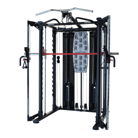
- Page 1 SCS-202 INSPIRE SMITH CAGE SYSTEM OPTION-2 ASSEMBLY AND OPERATION MANUAL (SCS-002 SMITH CAGE, SCS-102 SMITH BAR SOLD SEPARATELY) RECORD SERIAL NUMBER HERE www.inspirefitness.net by Health In Motion 11-15-14...
- Page 2 CONGRATULATIONS… You’ve just taken the first step to a healthier and stronger body. This Smith Cage System by Inspire Fitness offers the key to unlocking your body’s potential. Regular strength training has been shown to deliver a host of benefits including: increased muscle tone, decreased body fat, improved energy levels, a reduction in stress, and improved cardiac output.
-
Page 3: Table Of Contents
TABLE OF CONTENTS Section Description……………………………………………………. Page Important Safety Instructions………………………………………. Tools Required………………………………………………………………… Parts & Hardware List……………………………………………………. Cable Chart ……………………………………………………………………. Assembly Instructions……………………………………………………. Cable Adjustment ………………………………………………………….. Exploded View ……………………………………………………………….. Decal Reference …………………………………………………………….. Decal Placement …………………………………………………………… Accessories, Options, Training Tips………………….…………… General Maintenance Information…….…………………………… Maintenance Schedule…….……………………………………………… Limited Warranty…………………………………………………………….. -
Page 4: Important Safety Instructions
• Keep the Smith Cage System away from walls and clear of any obstructions and furniture. • Stop immediately if you experience shortness of breath, pain, or dizziness during your workout. Inspire Fitness strongly recommends consulting your doctor before starting an exercise program. TOOLS REQUIRED FOR ASSEMBLY •... -
Page 5: Parts & Hardware List
M8 Washer 10 Weight Racks M10 Washer 11 Plastic End Cap 12 Safety Bars M10 Locknut 13 Touch-up Paint Parts Description SCS-202 Box Hardware in SCS-202 Box Item Item Evs p/n Evs p/n Right Top Cable Column Mount Bolt, M6 x 12 (Button Head) -
Page 6: Cable Chart
CABLE CHART UPPER CABLE Qty: 2 GM698-500-002 LOWER CABLE Qty: 2 GM698-500-001 ROW CABLE Qty: 2 GM698-500-003 GUIDE CABLE Qty: 2 GM698-500-004 Page 3... -
Page 7: Assembly Instructions
ASSEMBLY INSTRUCTIONS Page 4... - Page 8 Step 1 2 – M10 x 25 Hex Bolts (Blue Dot) 4 - M10 x 125 Hex Bolts 10 – M10 Flat Washers 4 – M10 Locknuts Right Base Beam Weight Stack Mount Cable Anchor Plate Left Base Beam Base Beam Bracket Two (M10 x 25 Hex Bolts (Blue Dot) Step 1: Attach the Right Base Beam, Left Base Beam, Four (M10 x 125 Hex Bolts)
- Page 9 Weight Rack mounting tabs Main Upright Step 2 4 – M10 x 105 Hex Bolts 8 – M10 Flat Washers 4 – M10 Locknuts Four (M10 x 105 Hex Bolts) Step 2: Attach two Main Uprights to the rear of the Left and Right Eight (M10 Flat Washers) Right Base Beams (orient all Uprights with the four Weight Four (M10 Locknuts)
- Page 10 Main Upright Weight Rack mounting tabs Row Pulley Mount Step 3 4 - M10 x 110Hex Bolts 8 - M10 Flat Washers 4 – M10 Locknuts Lower Right Cable Column Mount Step 4 2 – M10 x 100 Hex Bolts 4 –...
- Page 11 Note: Two tabs to rear Rear Cross Brace Step 5 2 - M8 x 20 Hex Bolts 2 - M10 Flat Washers Pull-Up Bar Cross Brace Step 6 2 - M8 x 20 Hex Bolts 2 - M8 Flat Washers Step 5: Attach the Pull-Up Cross Brace to top of front Two (M8 x 20 Hex Bolts) Main Uprights using:...
- Page 12 Right Top Beam Left Top Beam Top Right Cable Column Mount Step 7 2 - M10 x 100 Hex Bolts (Blue Dot) 2 - M10 x 110 Hex Bolts 6 - M10 Flat Washers 2 - M10 Locknuts Top Left Cable Column Mount Step 8 Top Weight Stack Mount...
- Page 13 Lat Attachment 3 ½” Dia. Pulleys Step 10 2 - M10 x 155 Hex Bolts 1 - M10 x 105 Hex Bolt 6 - M10 Flat Washers 3 - M10 Locknuts Rear Cross Brace Step 10: Assure the M12 Hex Bolt from STEP 9 is installed in the top of the Row Pulley Mount and adjusted to the minimum height.
- Page 14 Step 10: Lat Attachment, Low Profile Option For a lower profile machine, remove the two Brackets and bolt the Lat Attachment directly One (M10 x 95 Button Head Bolt) to the Pull-Up Cross Brace with one M10 x 95 Two (M10 Flat Washers) Button Head Bolt, pointing up through it using: One (M10 Locknuts) (Wrench Tighten Now)
- Page 15 Guide Rods Shroud Mount Plates Shroud Plate Spacers Step 12 4 - M10 x 60 Hex Bolts, Blue Dot 4 - M10 x 95 Hex Bolts 12 - M10 Flat Washers 4 - M10 Locknuts NOTE: The back side of the Shroud Weight Stack Mount Plate has only one hole.
- Page 16 Step 13 Selector Stem/Top Weight Assembly Front of Weight Plate has recessed area for Weight Plate Number Stickers Weight Plate Bottom of weight plate has three feet Top Weight Pulley and M12 Jam Nut Rubber Donuts Weight Stack Risers Shroud Plates NOTE: Before beginning Step 13: If optional 200 lb.
- Page 17 Step 14 4 - M10 x 45 Hex Bolts 8 - M10 Flat Washers 4 - M10 Locknuts Weight Stack Shroud Mounts Step 14: Install the two Weight Stack Shroud Mounts. One at a time, Four (M10 x 45 Hex Bolts) position the Weight Stack Shroud Mounts at the top of the Eight (M10 Flat Washers) Guide Rod pairs.
- Page 18 Right Top Cable Column Mount Left Top Cable Column Mount Step 15 4 - M10 x 60 Hex Bolts 8 - M10 Flat Washers 4 - M10 Locknuts Left Cable Column Slider Cable Column Tubes Right Cable Column Slider Lower Right Cable Column Mount Lower Left Cable Column Mount Step 15: Identify one of the Cable Column Tube’s upper end, (the end with the slotted holes).
- Page 19 Cable End Pulleys #8 and #9 Pulleys #5 and #6 Pulley #1 Step 16 1 - Upper Cable Pulley #2 1 - 3 ½” Dia. Pulley 1 - M10 x 70 Hex Bolt Upper Cable inside Left Top 2 - 1/2” Step Spacers Upper Cable inside tube Beam tube 1 - M10 Locknut...
- Page 20 Cable End Pulleys #5 and #6 Cable inside tube Pulleys #8 and #9 Step 17 Pulley #2 1 - Upper Cable 1 - 3 ½” Dia. Pulley Pulley #11 1 - M10 x 70 Hex Bolt 2 - 1/2” Step Spacers 1 - M10 Locknut Pulley #1 Floating Pulley Assy.
- Page 21 Floating Pulley Assy. with Guide Bushing Step 18 1 - Lower Cable 1 - M10 x 35 Hex Bolt 1 - M10 x 50 Hex Bolt 1 - M10 x 55 Hex Bolt (Blue Dot) 4 - M10 Flat Washers Lower Cable “U”...
- Page 22 Step 19 Floating Pulley Assy With Guide Bushing 1 - Lower Cable 1 - M10 x 35 Hex Bolt 1 - M10 x 50 Hex Bolt 1 - M10 x 55 Hex Bolt (Blue Dot) 4 - M10 Flat Washers 2 - M10 Locknuts 1 - 1/2”...
- Page 23 Step 20 1 – Row Cable 1 - Plastic Ball 1 - “U” Bracket 1 - Spring Clip 1 - M6 x 20 Button Head Bolt 1 - M6 Flat Head Nut Floating Pulley Assy. Row Pulley Mount Left Row Cable Cable End Detail Start Left Row Cable here Step 20: Select the two Row Cables and lay them out straight assuring they are not kinked.
- Page 24 Step 21 1 - Row Cable 1 - Plastic Ball 1 - “U” Bracket 1 - Spring Clip 1 - M6 x 20 Button Head Bolt 1 - M6 Flat Head Nut Row Pulley Mount Right Row Cable Cable End Detail Row Cable End Start Right Row Cable Here Step 21: Repeat all of Step 20 on the right side of the gym using:...
- Page 25 Step 22 Attach Guide Cables Hook on bottom of Top Weight Stack Mount Bushing in Floating Pulley Assembly Guide Cable Base Beam Step 22: Feed the small end of the Guide Cable up through the bushing in the Floating Pulley Assembly and attach the end to the hook on the bottom of the Top Weight Stack Mount.
- Page 26 Step 23 16 - M10 x 25 Hex Bolts 32 - M10 Flat Washers 16 - M10 Locknuts Step 23: Attach the four Weight Rack Plates onto the outer sides of the mounting tabs on the Main Uprights with the “Hooks” pointing up using: Sixteen (M10 x 25 Hex Bolts) Thirty Two (M10 Flat Washers) Sixteen (M10 Locknuts)
- Page 27 Exercise Placard Step 24 6 - M6 x 35 Button Head Bolts 6 - M6 Flat Washers 6 - M6 Locknuts Row Pulley Mount Step 25 6 - End Caps Step 24: Attach the Exercise Placard to the Row Pulley Mount using: Six (M6 x 35 Button Head Bolts) Six (M6 Flat Washers) Six (M6 Locknuts)
- Page 28 Shroud Plate Connector Shroud Tightening Knobs Pins Step 26 While sliding the Shroud Bracket into the pocket of the Fabric Shroud, align the hole in the bracket with square opening in the back of the shroud Upper Shroud Mount Plate Shroud Bracket Lower Shroud Mount Plate...
-
Page 29: Cable Adjustment
Step 27 Step27: Initially adjust the four cable bolts to 1” between the top of the bolt and the bracket it is attached too and Wrench Tighten the Jam Nuts. Start with one Cable and adjust the slack out. Then do the same with the other three Cables. -
Page 30: Exploded View
EXPLODED VIEW Exploded View not available at this time. Please contact customer service at 1-877-738-1728 for assistance or a copy. Page 27... -
Page 31: Decal Reference
DECAL REFERENCE 877-738-1729 8,870,718. Weight Number Stickers PAGE 28... -
Page 32: Decal Placement
DECAL PLACEMENT “INSPIRE” Label “DANGER” Label Serial on both sides Number of safety tiers Label “WARNING” Label Patent Label “NOTICE” Label Page 29... -
Page 33: Accessories, Options, Training Tips
ACCESSORIES • 4 Ring “D” Handles – two pieces • Ankle Strap – one piece • “D” Handle / Ab Strap – two pieces • Pull-up Assist Strap – one piece Smith Cage System OPTIONS • SCS-102 (SMITH MACHINE OPTION) •... -
Page 34: General Maintenance Information
GENERAL MAINTENANCE INFORMATION • Periodically inspect the cables for splitting, cracking or fraying. Also, watch for bulging or flat areas in the cable. • Immediately replace cables at the first signs of damage or wear. Never use equipment with damaged or worn cables. •... -
Page 35: Maintenance Schedule
MAINTENANCE SCHEDULE HOME ROUTINE ENTRY DATE MAINTENANCE Inspect: Links, Pull Pins, WEEKLY Spring Clips, Swivels, Weight Stack Pins WEEKLY Clean: Upholstery Inspect: Cables and WEEKLY their Fittings Inspect: Tautness of all WEEKLY Shrouds Inspect: Accessory Bars 3 MONTHS and Handles 3 MONTHS Inspect: All Decals Inspect: All Nuts and... -
Page 36: Limited Warranty
This is the only express warranty applicable to Health In Motion’s “Inspire” branded strength products. Health In Motion neither assumes nor authorizes anyone to assume for it any other express warranty.
Need help?
Do you have a question about the SCS-202 and is the answer not in the manual?
Questions and answers