
Related Manuals for Inspire SF5


Summary of Contents for Inspire SF5
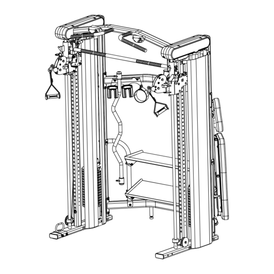
- Page 1 Model # SF5.1 USER MANUAL START HERE Machine shown with optional bench and rack attachment Record Serial Number Here Health in Motion LLC V09222023 MADE IN CHINA...
- Page 3 CONGRATULATIONS Welcome to the Inspire Fitness Family. You’ve just taken the first step to a healthier and stronger body. This SF5 Smith Machine Functional Trainer by Inspire Fitness offers the key to unlocking your body’s potential. Regular training on a Smith Machine Functional Trainer has been shown to deliver a host of benefits including: increased muscle tone, decreased body fat, improved energy levels, and a reduction in stress.
-
Page 4: Table Of Contents
TABLE OF CONTENTS PRODUCT WARRANTY................5 IMPORTANT SAFETY NOTICE..............5 ASSEMBLY AND SETUP................6 ASSEMBLY INSTRUCTIONS..............10 FEATURES AND FUNCTIONS..............19 LABEL PLACEMENT................20 LIVE AREA....................21 PRODUCT DIMENSIONS................22 MAINTENANCE..................23 EXPLODED VIEW..................24 PARTS LISTS....................25 Pg. 4 V09222023... -
Page 5: Product Warranty
PRODUCT WARRANTY To view full warranty details, or to register your product for warranty, visit inspirefitness.com/support AUSTRALIA Our goods come with guarantees that cannot be excluded under the Australian Consumer Law. You are entitled to a replacement or refund for a major failure and for compensation for any other reasonably foreseeable loss or damage. You are also entitled to have the goods repaired or replaced if the goods fail to be of acceptable quality and the failure does not amount to a major failure. -
Page 6: Assembly And Setup
ASSEMBLY AND SETUP Package Contents Pg. 6 V09222023... - Page 7 Assembly Hardware Kit (Not to Scale) V09222023 Pg. 7...
- Page 8 Pg. 8 V09222023...
- Page 9 6-Cable Ties 2-Smithbar spacers 2-Weight Pin 1 - M5 Hex Key 1 - M8 Hex Key 1 - #10 Wrench (Tool) 2 - #14 & #17 Wrench (Tool) unit: mm V09222023 Pg. 9...
-
Page 10: Assembly Instructions
ASSEMBLY INSTRUCTIONS STEP 1 A. Make sure any packing material or supports are removed from the frames prior to assembly. Start by placing the Right Main Frame (6) in the vertical position. Having a second person to hold the frame is helpful or you can possibly lean the frame against a wall. - Page 11 STEP 2 Place the Pull-up Crossbar (3) in position between the two main frames and insert four M10x75mm Hex Bolts (39) with M10 Flat Washers (43) through each main frame. Place M10 Flat Washers (43) and M10 Locknuts (42) onto the bolts. DO NOT TIGHTEN THE HARDWARE AT THIS TIME.
- Page 12 STEP 4 A. Thread the Weight Stack Pulley (14) into the top of both the Top Plate Assembly (8), leave about a ¼ inch of thread. B. Insert the Weight Stack Guide Rods (7) through the holes in the bottom of the frame. Be sure the ends of the rods with the holes are facing down, and do your best to align them with the holes in the frame.
- Page 13 STEP 4 (Continued) D. Make sure the cable that runs from either side of the frame is positioned between the two guide rods. Carefully pull the guide rods toward each other, then slide the Guide Rod Bushings (10) up into the larger hole of the frame until the slot of the bushing is resting in the frame.
- Page 14 STEP 5 A. Route the cable as shown. Remove the pulley from the Weight Stack Pulley (14) assembly in order to route the cable into it, leave the hardware loose. B. Adjust the cable tension by rotating the cam bolt until the Top Plate Assembly (8) starts lifting slightly from the weight stack.
- Page 15 STEP 6 Bolt the smith bar hooks to each side of the main frames. The Right Smith Bar Hook (35) is the mount with the locking pin, the Left Smith Bar Hook (36) is the mount without the pin. Use three M8x16 Buttonhead Cap Screws (44) with M8 Washers (45) per hook to attach to them to the frame as shown.
- Page 16 STEP 8 There are three different widths of weight stack shrouds. The widest Shroud (17) is placed on the outside facing part of the weight stack, the Medium (17) and Narrow (17) width shrouds are placed together on the inside, with the smaller placed toward the back of the machine.
- Page 17 STEP 9 A. Place the Accessory Rack (31) on right side of the Upper Crossbar (2). Insert two M10 x 75mm Hex Bolts (39) with M10 Flat Washers (43) through the rack and crossbar. Place M10 Flat Washers (43) and M10 Locknuts (42) onto the bolts. Tighten the hardware.
- Page 18 STEP 9 (Continued) E. Place the 5 Lb Add On Weights (23), Dual Hook Curl Bar (24), Triceps Rope (25), Chin/Dip Belt (26), and Ankle Strap (27), on the accessory racks as shown. Note: to use the 5 lb Add On Weight place them on top of the weight stacks in between the pullies.
-
Page 19: Features And Functions
FEATURES AND FUNCTIONS Smithbar storage and lock. Lift and rotate the bar until both sides are resting on the hooks. Rotate the lock pin until it springs into the lock position. To unlock the bar, pull and rotate the pin out of the slot. Pull-up bars Rock climbing grips Smithbar... -
Page 20: Label Placement
LABEL PLACEMENT Machine shown with optional bench and rack attachment Pg. 20 V09222023... -
Page 21: Live Area
LIVE AREA 2.7 m 9 ft 9 pi Machine shown with optional bench and rack attachment 2.4 m 8 ft 2.4 m 8 pi 8 ft 8 pi V09222023 Pg. 21... -
Page 22: Product Dimensions
PRODUCT DIMENSIONS 213 cm 84 in 84 po 122 cm 48 in 150 cm 48 po 59 in 59 po Machine shown with optional bench and rack attachment Pg. 22 V09222023... -
Page 23: Maintenance
• Inspect snap links, swivels, handles and weight stack pin for wear or damage. If wear or damage exists, replace with Inspire Fitness parts only. • Locate and familiarize yourself with all warning decals on the Smith Machine Functional Trainer. -
Page 24: Exploded View
EXPLODED VIEW Pg. 24 V09222023... -
Page 25: Parts Lists
PARTS LISTS Description Part Number Qty. Description Part Number Qty. GM697260001PZ Lower Crossbar 0111-010-058 M10X115 mm Hex Bolt 0110-710-008 M10 Locknut GM697260002PZ01 Upper Crossbar 0116-010-008 M10 Flat Washer GM697220003PZ Pull-up Crossbar 0113-208-168A M8x16mm Button Head Cap Screw GM697320004PZ01 Smith bar 0116-008-028 M8 Washer GM697200010PZ...
Need help?
Do you have a question about the SF5 and is the answer not in the manual?
Questions and answers