Inspire FT-1 Assembly & Operation Manual
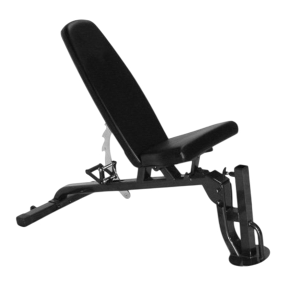
Bench (fidb)
Hide thumbs
Also See for FT-1:
- Assembly & operation manual (22 pages) ,
- Assembly & operation manual (33 pages)

Related Manuals for Inspire FT-1


Summary of Contents for Inspire FT-1
- Page 1 ASSEMBLY & OPERATION MANUAL FT-1 BENCH (FIDB) RECORD SERIAL NUMBER HERE www.inspirefitness.net by Health In Motion LLC July 2011...
-
Page 2: Before You Begin
Use the parts list included in this manual to verify that all parts are accounted for before assembly. If any parts are missing, contact the retailer of this home gym for replacement parts. Or, call Inspire at 877-738-1729 Service of your home gym should only be preformed by an authorized INSPIRE retailer. -
Page 3: Important Safety Notice
IMPORTANT SAFETY NOTICE PRECAUTIONS This exercise bench is built for optimum safety. However, certain precautions apply whenever you use a piece of exercise equipment. Be sure to read the entire manual before you assemble or use your bench. In particular, note the following safety precautions: 1. -
Page 4: Parts List
PARTS LIST Part# Description Q'ty (pcs) M10 M 10 x x 3 3 ¾” ¾ ” Ø ¾” Washer Ø 5/8” Washer Front Post Assembly Main Seat Support Assembly Rear Stabilizer M8 M 8 x x 1” 1 ” Backrest Board Seat Pad 10 1 0 M8 M 8 x x 2 2 3/4”... - Page 5 Hardware and Tool List Note: The following parts are not drawn to scale. Please use your own ruler or scale to measure sizes. PAGE 4 7/2011...
- Page 6 BENCH ASSEMBLY INSTRUCTIONS STEP 1 A.) Attach the Main Seat Support (#5) onto the Front Post (#4). B.) Secure it with two M10 x 3 ¾” Allen Bolts (#1), four Ø ¾” Washers (#2), and two M10 Aircraft Nuts (#11). C.) Do not tighten the Nuts and Bolts yet.
- Page 7 STEP 2 make Attach the Main Seat Support (#5) onto the Rear Stabilizer (#6) sure Warning Sticker is facing up. B.) Secure it with two M10 x 3 ¾” Allen Bolts (#1), four Ø ¾” Washers (#2), and two M10 Aircraft Nuts (#11). C.) Securely tighten all Nuts and Bolts installed.
- Page 8 STEP 3 A.) Place the Seat Pad (#9) onto the Main Seat Support Assembly (#5). B.) Secure it with four M8 x 1” Allen Bolts (#7) and Ø 5/8” Washers (#3). PAGE 7 6/2011...
- Page 9 STEP 4 Attach the Backrest Board (#8) to the Main Seat Support Assembly (#5). Secure it with two M8 x 2 3/4” Allen Bolts (#10) and Ø 5/8” Washers (#3). When adjusting the Backrest Board to an incline position, simply pull up the board.
-
Page 10: Exploded Diagram
EXPLODED DIAGRAM PAGE 9 7/2011... -
Page 11: General Maintenance Information
GENERAL MAINTENANCE INFORMATION • Regularly inspect product for loose hardware. • Do not use or store equipment outdoors. • Locate and familiarize yourself with all warning decals on the home gym. • Replace damaged or worn upholstery immediately. PAGE 10 7/2011... -
Page 12: Limited Warranty
LIMITED WARRANTY In-Home Lifetime Warranty. This Warranty applies only in the United States to Inspire strength products manufactured or distributed by Health In Motion LLC. The warranty period to the original purchaser is lifetime of the original purchaser. Health In Motion warrants that the Product you have purchased for non-commercial, personal, family or household use from Health In Motion LLC or from an authorized Health In Motion reseller is free from defects in materials or workmanship under normal use during the warranty period.
Need help?
Do you have a question about the FT-1 and is the answer not in the manual?
Questions and answers