Table of Contents
Advertisement
Quick Links
Revised: July 30, 2014
™
Lexmark
C746n, C746dn, C746dtn,
C748e, C748de, C748dte, and CS748de
5026-3xx, 5xx
• Table of contents
• Start diagnostics
• Safety and notices
• Trademarks
• Index
Lexmark and Lexmark with diamond design are
trademarks of Lexmark International, Inc., registered
in the United States and or other countries.
Advertisement
Table of Contents

Subscribe to Our Youtube Channel
Related Manuals for Lexmark C746n


Summary of Contents for Lexmark C746n
- Page 1 C748e, C748de, C748dte, and CS748de 5026-3xx, 5xx • Table of contents • Start diagnostics • Safety and notices • Trademarks • Index Lexmark and Lexmark with diamond design are trademarks of Lexmark International, Inc., registered in the United States and or other countries.
- Page 2 Lexmark, Lexmark with diamond design, and MarkNet are trademarks of Lexmark International, Inc., registered in the United States and/or other countries. PrintCryption is a trademark of Lexmark International, Inc.
-
Page 3: Table Of Contents
5026 Table of contents Previous Notices and safety information ......... . . ix Laser notice . - Page 4 5026 144.xx—Motor (EP drive assembly middle cartridge) error service check ....2-52 Previous 145.xx—Motor (EP drive assembly bottom cartridge) error service check ....2-54 146.xx, 148.xx—Motor (MPF/duplex) error service check .
- Page 5 5026 920.11—POST (power-on self test)—Two toner sensors not connected error service check 2-106 Previous 920.12—POST (power-on self test)—One toner sensor not connected error service check . 2-108 920.13—POST (power-on self test) cartridge motor 1 not connected error service check . . 2-109 920.14—POST (power-on self test)—Cartridge motor 2 not connected error service check .
- Page 6 5026 Download Emuls ..............3-30 Previous Demo Mode .
- Page 7 5026 Paper tray dust cover removal ........... . 4-46 Previous Rear frame cover removal .
- Page 8 5026 Waste toner assembly removal ........... 4-184 Previous Waste toner HV contact assembly removal .
-
Page 9: Notices And Safety Information
5026 Notices and safety information Previous The following laser notice labels may be affixed to this printer. Next Laser notice Go Back This product is certified in the U.S. to conform to the requirements of DHHS 21 CFR Subchapter J for Class I (1) laser products, and elsewhere is certified as a Class I laser product conforming to the requirements of IEC 60825-1. -
Page 10: Aviso Sobre O Laser
5026 Previous Avvertenze sui prodotti laser Questo prodotto è certificato negli Stati Uniti come prodotto conforme ai requisiti DHHS 21 CFR Sottocapitolo J per i prodotti laser di Classe I (1), mentre in altri paesi è certificato come prodotto laser di Classe I conforme ai requisiti IEC 60825-1. - Page 11 5026 Previous Laserinformatie Dit product is in de Verenigde Staten gecertificeerd als een product dat voldoet aan de vereisten van DHHS 21 CFR paragraaf J voor laserproducten van klasse I (1). Elders is het product gecertificeerd als een laserproduct van klasse I dat voldoet aan de vereisten van IEC 60825-1. Next Laserproducten van klasse I worden geacht geen gevaar op te leveren.
- Page 12 5026 Previous Laser-notis Denna produkt är certifierad i USA i enlighet med kraven i DHHS 21 CFR underkapitel J för klass I (1)- laserprodukter, och på andra platser certifierad som en klass I-laserprodukt i enlighet med kraven i IEC 60825-1. Next Klass I-laserprodukter betraktas inte som skadliga.
- Page 13 5026 Previous Next Go Back Notices and safety information xiii...
- Page 14 5026 Previous Next Go Back Service Manual...
-
Page 15: Lithium Warning
5026 Previous Lithium warning CAUTION This product contains a lithium battery. THERE IS A RISK OF EXPLOSION IF THE BATTERY Next IS REPLACED BY AN INCORRECT TYPE. Discard used batteries according to the battery manufacturer’s instructions and local regulations. Go Back Safety information The safety of this product is based on testing and approvals of the original design and specific •... - Page 16 5026 Previous Sicherheitshinweise • Die Sicherheit dieses Produkts basiert auf Tests und Zulassungen des ursprünglichen Modells und bestimmter Bauteile. Bei Verwendung nicht genehmigter Ersatzteile wird vom Hersteller keine Verantwortung oder Haftung für die Sicherheit übernommen. Next Die Wartungsinformationen für dieses Produkt sind ausschließlich für die Verwendung durch einen •...
- Page 17 5026 Previous Informació de Seguretat • La seguretat d'aquest producte es basa en l'avaluació i aprovació del disseny original i els components específics. El fabricant no es fa responsable de les qüestions de Next seguretat si s'utilitzen peces de recanvi no autoritzades. •...
-
Page 18: Preface
5026 Preface Previous This manual contains maintenance procedures for service personnel. It is divided into the following chapters: General information contains a general description of the printer and the maintenance approach used to Next repair it. Special tools and test equipment, as well as general environmental and safety instructions, are discussed. -
Page 19: Navigation Buttons
5026 Previous CAUTION This type of caution indicates there is a danger from hazardous voltage in the area of the product where you are working. Unplug the product before you begin, or use caution if the product must receive power in order to perform the task. Next Go Back CAUTION... - Page 20 5026 Previous Next Go Back Service Manual...
-
Page 21: General Information
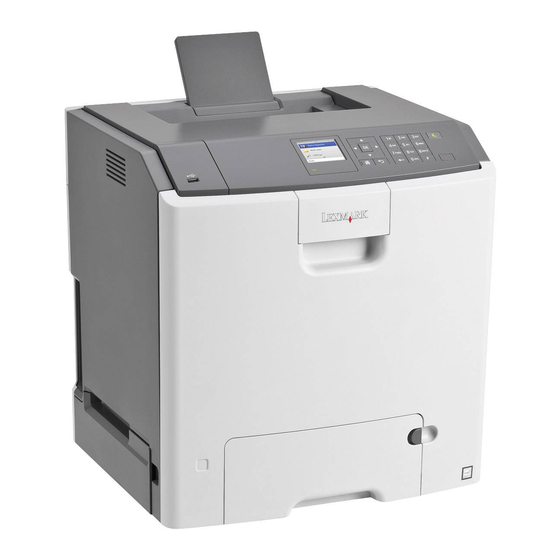
5026 1. General information Previous The Lexmark™ C746x and C748x family of color laser printers. Next Models Go Back Machine type Printer name Description and model Lexmark C746n 5026-310 Network-ready Lexmark C746dn 5026-330 Network-ready with duplex Lexmark C746dtn 5026-330 Network-ready with duplex and 550 sheet tray... -
Page 22: Media Options
650 sheets, the C746x and C748x supports up to 4300 sheets. The Lexmark C74x options are compatible with the Lexmark C73x SFP, X73x MFP, and X74x MFP, but not with any other Lexmark printers. No other options are supported by the C74x. -
Page 23: Memory Options
5026 Memory options Previous Additional memory card—The memory options for the C746x and C748x printers are 200 pin DDR2, • SODIMM, and they are available at 256MB, 512MB, and 1GB sizes. Flash memory card—Flash Memory cards are available in 256MB. •... -
Page 24: Printer Specifications
The following table contains the dimensions and weight for each of the respective printer models. This does not Next include packaging. Go Back Height Width Depth Weight Basic printer (C746n/dn) 454.7 mm 435.0 mm 400.0 mm 25.2 kg (17.9 in) (17.1 in) (15.7 in) (55.6 lbs) -
Page 25: Clearances
5026 Clearances Previous Next Go Back Number Description Clearance Right side 101.6 mm (4 in.) Front 609.6 mm (24 in.) Left side 152.4 mm (6 in.) Rear 152.4 mm (6 in.) 304.8 mm (12 in.) Memory C746 C748 Standard memory—The standard RAM is soldered onto the system board. Memory size 512MB 512MB... -
Page 26: Expansion Opportunities
5026 Expansion opportunities Previous Interface card expansion slots Code Enhancement Socket (application solution firmware) Next Hard disk Interface (for optional hard disk) Go Back Resolution The following resolutions are available: • 4800CQ (default resolution) 1200 x 1200 dpi (at reduced printer speed) •... -
Page 27: Electrical And Power Specifications
220 to 240 V at 50 to 60 Hz (not available in all countries) • 198 to 259 V, extreme • Notes: Using a power converter or inverter with the Lexmark C740 Series printers is not recommended. • The C740 series duplex models (C746dn, C746dtn, C748de, C748dte) are Energy Star Qualified. • •... -
Page 28: Acoustic Specifications
5026 Acoustic specifications Previous All acoustic measurements are made in accordance with ISO 7779:1999—Accoustics: Measurement of airborne noise emitted by information technology and telecommunications and reported in conformance with ISO 9296: 1988-04-15—Accoustics Declared noise emission values of computer and business equipment. Next 1 meter average sound pressure Declared sound power level... -
Page 29: Media Specifications
Under high humidity conditions (over 60%), envelopes may seal during printing. • Transparencies Use letter or A4-size transparencies for color laser printers only. • See Ordering Information for the recommended transparencies for the Lexmark C746x/C748x laser • printers. Do not use inkjet transparencies. •... - Page 30 5026 Using recycled paper and other office papers Previous Recycled office paper produced specifically for use in laser (electrophotographic) printers may be used in your printer. However, no blanket statement can be made that all recycled paper will feed well. Generally, the following property guidelines apply to recycled paper.
-
Page 31: Input And Output Capacities
5026 Input and output capacities Previous The following table describes the media options that each model supports, and the estimated capacities in stand and maximum configurations. Capacity may vary and is subject to media specifications and printer operating environment. The capacities are based on plain paper at 75g/m Next Standard input sources Primary tray capacity (sheets) -
Page 32: Input And Output Sizes And Types
5026 Input and output sizes and types Previous Next Media Sizes Go Back Paper sizes ✓ ✓ ✓ ✓ ✓ ✓ A4 210 x 297 mm A5 148 x 210 mm ✓ ✓ ✓ ✓ ✓ A6 105 x 148 mm ✓... - Page 33 5026 Previous Media Sizes (continued) Next Go Back Envelopes ✓ ✓ C6 Envelope 114 x 162 mm B6 Envelope 125 x 176 mm ✓ ✓ C65 Envelope 114 x 229 mm ✓ ✓ C5 Envelope 162 x 229 mm ✓ ✓...
-
Page 34: Paper Guidelines
5026 Previous Media weight, primary tray and option tray Size Type Weight A5, JIS B5, Executive Xerographic and bond Long grain 75 g/m –177 g/m (20 lb to 47 lb) Short grain 90 g/m –218 g/m (24 lb–58 lb) Next Universal Xerographic and bond Long grain... - Page 35 5026 Preprinted papers that require a registration (the precise print location on the page) greater than ±2.3 mm • Previous (±0.9 in.), such as optical character recognition (OCR) forms Note: In some cases, registration can be adjusted with a software application to successfully print on these forms.
-
Page 36: Tools Required For Service
5026 Storing paper Previous Use these paper storage guidelines to help avoid jams and uneven print quality: For best results, store paper where the temperature is 21°C (70°F) and the relative humidity is 40%. Most • label manufacturers recommend printing in a temperature range of 18 to 24°C (65 to 75°F) with relative Next humidity between 40 and 60%. -
Page 37: Acronyms
5026 Previous Acronyms BLDC Brushless DC Motor Back Up Roll Cyan Next Color On Demand DIMM Dual Inline Memory Module DRAM Dynamic Random Access Memory Go Back Electrophotographic Process Electrostatic Discharge Field Replaceable Unit Gigabyte HCIT High-Capacity Input Tray HVPS High Voltage Power Supply Black LASER... - Page 38 5026 Previous Next Go Back Service Manual 1-18...
-
Page 39: Diagnostic Information
5026 2. Diagnostic information Previous Start Next CAUTION Remove the power cord from the electrical outlet before you connect or disconnect any cable Go Back or electronic card or assembly for personal safety and to prevent damage to the printer. CAUTION—POTENTIAL INJURY: The printer weight is greater than 54 lbs (24.5kg), and requires two or more trained personnel to lift safety. -
Page 40: Operator Panel And Menus
5026 Previous Operator panel and menus C746x operator panel Next Go Back WXYZ C746x buttons and light descriptions Use the Display • View printer status. • Allow printer setup and operation. Select button Submit changes made in the printer settings. Navigation buttons Scroll up and down or left and right. -
Page 41: C748X Operator Panel
5026 Previous Use the Indicator light Check the status of the printer. Indicator light Indicates status Next Printer power is off. Blinking green Printer is warming up, processing data, or printing a job. Go Back Solid green Printer is on, but idle. Blinking red Operator intervention is required. - Page 42 5026 Previous Use the Sleep button Enable Sleep mode. The following are the statuses based on the indicator light and the Sleep button:. • Entering or waking from Sleep mode Next - The indicator light is illuminated solid green. - The Sleep button is un-illuminated. •...
- Page 43 5026 Using the touch screen buttons Previous Note: Your home screen, icons, and buttons may vary depending on your home screen customization settings, administrative setup, and active embedded solutions. Next Go Back Touch Up arrow Scroll up. Delete folder Delete the file you selected. Left arrow Scroll to the left.
- Page 44 5026 Previous Touch Accept Save a setting. Next • Cancel an action or a selection. Cancel • Cancel out a screen and return to the previous screen Go Back Back Navigate back to the previous screen. Understanding the home screen When the printer is turned on, the display shows a basic screen, referred to as the home screen.
- Page 45 5026 Previous Touch Status message bar • Show the current printer status such as Ready or Busy. • Show printer conditions such as Fuser missing or Cartridge Low. • Show intervention messages and the instructions on how to clear them. Status/Supplies •...
-
Page 46: Administrative Menus
5026 Administrative menus Previous Note: Some menu items may not be available based on the printer model or the options installed. Supplies Menu Paper Menu Reports Settings Next Replace Supply Default Source Menu Settings Page General Settings Cyan Cartridge Paper Size/Type Device Statistics Flash Drive Menu Magenta Cartridge... -
Page 47: Power-On Self Test (Post) Sequence
When you turn the printer on, it performs a Power-On Self Test. Check for correct POST functioning of the base printer by observing the following: Next The operator panel turns on and displays the Lexmark logo. A progress bar displays. The LED turns on. -
Page 48: Print Quality Symptom Table
5026 Print quality symptom table Previous Symptom Action Background Go to “Print quality—background” on page 2-132. Blank page Go to “Print quality—blank page” on page 2-133. Next Blurred or fuzzy print Go to “Print quality—blurred or fuzzy print” on page 2-135. -
Page 49: User Status And Attendance Messages
5026 Previous User status and attendance messages Error code Action Next Close Front Door Close the front door securely. If you continuously get this error, then either the 24 V interlock switch or the 5 V interlock switch is bad. See “24 V interlock switch service check”... - Page 50 5026 Previous Error code Action Load Manual <type> If paper loaded is in the manual feeder, the job continues. If paper is not in the feeder, <size> pressing Select indicates to the printer it should search for a source with the proper type and size.
- Page 51 5026 Previous Error code Action 3x through 8x attendance messages 31 Defective or Missing • Reseat the specified toner cartridge. <color> Cartridge Next • Inspect the smart chip card contacts (A) for damage, contamination or positioning error. If damaged, contact your next level of service. Go Back •...
- Page 52 5026 Previous Error code Action 37 Insufficient memory • Select Continue to print the portion of the job already stored and begin collating the rest to collate job of the job. • Cancel the current job. • If this does not fix the problem, replace the system board. See Next “System board removal”...
- Page 53 5026 Previous Error code Action 52 Flash Full • Select Continue to clear the message and continue printing. Note: Downloaded fonts and macros not previously stored in flash memory are deleted. • Delete fonts, macros, and other data stored in flash memory. Next •...
- Page 54 5026 Previous Error code Action 57 Configuration Configuration changes may be: Change • Code version changes Held Jobs May Not • Paper handling options removed Be Restored Next • The disk was installed from a different model or speed of printer. 58 Too Many Flash Too many flash options are installed.
- Page 55 5026 Previous Error code Action 80 Fuser Life Warning • Select Continue to clear the message and continue printing. • Show Me, View Supplies, and Tell Me More displays additional information. • Order a replacement fuser. When print quality is reduced, install the new fuser using the instruction sheet that comes with the replacement fuser.
- Page 56 5026 Previous Error code Action 82 Waste Toner Missing • Insert the waste toner box. • Inspect the top cover camshaft assembly for proper operation. When the top access cover is closed, the printer should mechanically interlock. • Check the cable in connector JBUMP1on the system board for defects and proper Next connection.
- Page 57 5026 Previous Error code Action 84 <color> PC Unit • Scroll down the operator panel to see if the printer is showing that all four of the PC units Missing are missing. If so, check the HVPS cable between the system board and the HVPS. Ensure that the cable is not plugged in backwards on the HVPS.
- Page 58 5026 Previous Error code Action 84 <color> PC Unit Near • Select Ignore to clear the message and continue printing. Life Warning • Order the specified photoconductor unit. When print quality is reduced, install the new specified photoconductor unit using the instruction sheet that comes with the replacement specified photoconductor unit.
-
Page 59: Error Codes And Messages
5026 Previous Error codes and messages Error code Description Action Next 1xx service error codes 110.01–110.07Mirror A mirror motor error has occurred. • POR the printer. Motor Error • If the error message persists, go to Go Back “110.xx— Mirror motor service check” on page 2-45. - Page 60 5026 Previous Error code Description Action 146.01–146.08 Duplex motor has failed. • POR the printer. Motor Error • If the error message persists, go to “146.xx, 148.xx—Motor (MPF/duplex) error service check” on page 2-55. Next 147.09–147.25 Aligner motor has failed. •...
- Page 61 5026 Previous Error code Description Action 168.xx HCIT elevator motor error. • POR the printer. Motor Error • If the error message persists, go to “168.xx— Motor (HCIT elevator) error service check” on page 2-65. Next 199.xx Unrecoverable RIP software error. •...
- Page 62 5026 Previous Error code Description Action 200.22 Pick (tray 1) motor stalled. • Check for anything in the paper path that might cause the paper to jam. Possible causes: • If clearing a paper jam does not fix the problem, •...
- Page 63 5026 Previous Error code Description Action 201.08 Exit sensor is never made. • Check for anything in the paper path that might cause the paper to jam. Possible causes: • The fuser exit sensor may not be functioning • Improper loading properly.
- Page 64 5026 Previous Error code Description Action 201.32 Paper is jammed between the input • Check for anything in the paper path that might sensor and the exit sensor during cause the paper to jam. input options warm-up. • Open input tray and clear paper jams. Possible causes: Next •...
- Page 65 5026 Previous Error code Description Action 202.31 Paper jam at exit sensor during warm- • Check for anything in the paper path that might cause the paper to jam. • The fuser exit sensor may not be functioning Possible causes: properly.
- Page 66 5026 Previous Error code Description Action 230.03 During duplex printing, the input • Check for anything in the duplex paper path that sensor never broke. might cause the paper to jam. This includes the paper guides in tray 1. Possible causes: •...
- Page 67 5026 Previous Error code Description Action 242.03 Pick timeout from tray 2 exceeded 1. Remove all media present in the paper path. without a tray 2 sensor break. 2. Ensure proper media is set for the type of paper used in tray 2. Possible causes: 3.
- Page 68 5026 Previous Error code Description Action 242.26 While feeding from tray 2, the pass 1. Clear away anything in the paper path that might thru sensor is not made. cause the paper to jam. 2. Ensure the proper media is set for the type of Possible causes: paper used in the lower tray.
- Page 69 5026 Previous Error code Description Action 243.03 Pick timeout from tray 3 exceeded 1. Remove all media present in the paper path. without a tray 3 sensor break. 2. Ensure proper media is set for the type of paper used in tray 3. Possible causes: 3.
- Page 70 5026 Previous Error code Description Action 243.26 While feeding from a lower tray, tray 3 1. Clear away anything in the paper path that might pass thru sensor is not made. cause the media to jam. 2. Make sure proper media is set for the type of Possible causes: paper used in lower feeding tray.
- Page 71 5026 Previous Error code Description Action 244.03 Pick timeout from tray 4 was 1. Remove all media present in the paper path. exceeded without a tray 4 sensor 2. Maker sure proper media is set for the type of break. paper used in tray 4.
- Page 72 5026 Previous Error code Description Action 244.21 Tray 4 motor stalled. 1. Remove all media present in the paper path. 2. Ensure proper media is set for the type of paper Possible causes: used. • Incorrect paper loading 3. Fan media, and stack it flat in the tray or Next •...
- Page 73 5026 Previous Error code Description Action 245.02 Tray 5 pass thru sensor made at • Check for anything in the paper path that might POR. cause the media to jam. • If the problem persists, go to “245.17—Paper Possible causes: Jam service check”...
- Page 74 5026 Previous Error code Description Action 245.21 Tray 5 motor stalled. 1. Remove all media present in the paper path. 2. Ensure proper media is set for the type of paper Possible causes: used. • Incorrect paper loading 3. Fan media, and stack it flat in the tray or Next •...
- Page 75 5026 Previous Error code Description Action 250.21 Multipurpose feeder motor stalled. 1. Remove all the media present in the paper path. 2. Ensure proper media is set for the type of paper Possible causes: used. • Multipurpose feeder motor failure 3.
- Page 76 5026 Previous Error code Description Action 9xx service error messages 900.00–900.99 Unrecoverable RIP software error. Go to “Steps before starting the 9yy service Software Error checks” on page 2-94. Next (except 900.05) Go to “900.00–900.99 (except 900.05)—System software error service check” on page 2-95.
- Page 77 5026 Previous Error code Description Action 920.04 Fuser motor not connected. • POR the printer. POST Error • If the error message persists, go to “920.04— POST (power-on self test) fuser motor not connected error service check” on Next page 2-100.
- Page 78 5026 Previous Error code Description Action 920.16 Bad printhead NVRAM data. • POR the printer. POST Error • If the error message persists, go to “920.16— POST (power-on self test)—Bad printhead NVRAM data error service check” on Next page 2-111. 920.17 Output bin cable not connected.
- Page 79 5026 Previous Error code Description Action 920.30 Option sensor disconnected. Use the following list to determine which service POST Error check to use: • Tray 2—Go to “242.02—Paper Jam service check” on page 2-72. Next • Tray 3—Go to “243.02—Paper Jam service check”...
- Page 80 5026 Previous Error code Description Action 945.04 Black transfer roll has failed. • POR the printer. Transfer Roll • If the error message persists, go to “945.xx, 947.xx—Transfer roll error service check” on page 2-119. Next 947.01 Yellow transfer roll has failed. •...
- Page 81 5026 Previous Error code Description Action 958.01–958.99 Processor failure. • POR the printer. Memory Failure • If the error message persists, replace the system board. See “System board removal” on page 4-163. Next 959.00–959.05 Invalid engine code • POR the printer. Engine Code Error •...
- Page 82 5026 Previous Error code Description Action 982.00–982.12 Communications error by specified 1. Turn the power off. <device> device. 2. Remove, and reinstall the option. Communications Error 3. Turn the main power back on. 4. Check all option interface connections if the Next problem remains.
-
Page 83: Service Checks
5026 Previous Service checks 31.xx—Cartridge errors service check Next Step Questions / actions POR the printer. Problem resolved. Go to step 2. Go Back Did this fix the problem? Replace the toner cartridge. Problem resolved. Go to step 3. Did this fix the problem? Reseat the toner cartridges and make sure Problem resolved. -
Page 84: Xx, 112.Xx, 113.Xx, And 114.Xx-Printhead Error Service Check
5026 Previous Step Questions / actions Turn the printer off, and then remove the rear Replace the printhead. See Go to step 3. frame cover. See “Rear frame cover “Printhead removal, 4-47. Check the cable in removal” on page installation, and connector JMIRR1 for proper connection to adjustment”... -
Page 85: Xx-Fuser Error Service Check
5026 120.xx—Fuser error service check Previous Step Questions / actions Check the input voltage switch on the back of Go to step 2. Set the switch for the the low-voltage power supply (LVPS). proper country voltage. Next Note: Some LVPS FRU do not have switches and switch automatically. - Page 86 5026 Previous Step Questions / actions Remove the rear frame cover. See“Rear Replace the fuser DC Go to step 5. 4-47. Check cable.See frame cover removal” on page “Fuser DC the cable in connector JFUSER1 (fuser DC cable removal” on cable) for proper connection to the system page 4-121.
-
Page 87: Xx, 920.02-Autocomp (Tray 1) Motor Error Service Check
5026 140.xx, 920.02—Autocomp (tray 1) motor error service check Previous Step Questions / actions 1. Turn the printer off. Problem resolved. Go to step 2. 2. Remove the rear frame cover. See Next “Rear frame cover removal” on page 4-47. 3. - Page 88 5026 Previous Step Questions / actions 1. Remove the right cover. See Go to step 3. Go to step 4. “Right cover removal” on page 4-51. 2. Check the cartridge motor 1/fuser motor cable for proper connection to the EP Next drive assembly (A), for pinch points for the cable, and for cable or connector damage.
-
Page 89: Xx-Motor (Ep Drive Assembly Top Cartridge 1 Motor) Error Service Check
5026 143.xx—Motor (EP drive assembly top cartridge 1 motor) error service check Previous Step Questions / actions 1. Turn the printer off. Replace the cartridge Go to step 2. motor 1/fuser cable. See 2. Remove the rear frame cover. See Next “Rear “Cartridge motor 1/fuser... -
Page 90: Xx-Motor (Ep Drive Assembly Middle Cartridge) Error Service Check
5026 Previous Step Questions / actions 1. Return the old motor 1/fuser motor cable. Replace the EP drive Go to step 6. assembly. See 2. Disconnect the motor drive cable from the EP drive assembly and connect it to the “Electrophotographic motor on a new EP drive assembly. - Page 91 5026 Previous Step Questions / actions Remove the right cover. See Replace the cartridge Go to step 3. “Right cover 4-51. Check the cartridge motor 2/3 cable. See removal” on page motor 2/3 cable for proper connection to the “Cartridge motor 2/3 EP drive assembly, pinch points for the cable, cable removal”...
-
Page 92: Xx-Motor (Ep Drive Assembly Bottom Cartridge) Error Service Check
5026 145.xx—Motor (EP drive assembly bottom cartridge) error service check Previous Step Questions / actions 1. Turn the printer off. Replace cartridge motor 2/ Go to step 2. 3 cable. See “Cartridge 2. Remove the rear frame cover. See Next “Rear motor 2/3 cable removal”... -
Page 93: Xx, 148.Xx-Motor (Mpf/Duplex) Error Service Check
5026 Previous Step Questions / actions 1. Return the old motor 1/fuser motor cable. Replace the EP drive Go to step 6. assembly. See 2. Disconnect the motor drive cable from the EP drive assembly and connect it to the “Electrophotographic motor on a new EP drive assembly. - Page 94 5026 Previous Step Questions / actions 1. Connect a new MPF motor with cable to Go to step 5. Replace the system board. the JDX1 connector on the system board “System board from outside of the machine. removal” on page 4-163.
-
Page 95: Xx, 906.05-906.08, 920.01-Post (Power-On Self Test) Aligner Error Service Check
5026 Previous Step Questions / actions 1. Check the front door assembly gears that Replace the front door Go to step 9. engages to the MPF/duplex gear for any assembly. See “Front damage. door assembly removal” 2. Close the front door assembly and open on page 4-108. -
Page 96: Xx-Cam Motor Error Service Check
5026 Previous Step Questions / actions 1. Disconnect the cable in connector Replace the paper pick Replace the system board. JFDPCK1 and connect the cable from the mechanism. See “Paper “System board new paper pick mechanism to JFDPCK1. pick mechanism removal”... - Page 97 5026 Previous Step Questions / actions Check the CAM motor cable from the cam Replace the EP drive Go to step 4. motor to the motor driver card for poor assembly. See connections or damage. “Electrophotographic (EP) drive assembly Next removal”...
-
Page 98: Xx-Cod (Color On Demand) Motor Service Check
5026 156.xx—COD (Color On Demand) motor service check Previous Step Questions / actions 1. Turn the printer off. Replace the COD Go to step 2. assembly. See “Color on 2. Remove the rear frame cover. See Next “Rear demand assembly frame cover removal”... -
Page 99: Xx, 163.Xx-Motor Error (Option Tray 3) Service Check
5026 Previous Step Questions / actions Remove the right cover. See Replace the option cable. Go to step 4. “Right cover removal” on page 4-51. “Option cable removal” on page 4-143. Check the option cable for pinch points and any damage. Next Go Back Is the cable damaged? -
Page 100: Xx, 165.Xx-Motor Error (Option Tray 4) Service Check
5026 Previous Step Questions / actions 1. Turn the printer off. Replace the option cable. • For 550 option, replace tray 3 550 input option. 2. Remove the rear frame cover. See “Option cable “Rear removal” on page 4-143. • For HCIT, replace the frame cover removal”... -
Page 101: Xx, 167.Xx-Motor Error (Option Tray 5) Service Check
5026 Previous Step Questions / actions 1. Turn the printer off. Replace the option cable. • For 550 option, replace tray 3 550 input option. 2. Remove the rear frame cover. See “Option cable “Rear removal” on page 4-143. • For HCIT, replace the frame cover removal”... - Page 102 5026 Previous Step Questions / actions Is the option tray 5 the high-capacity input tray Replace the HCIT top plate Replace the option tray 5 (2,000-sheet feeder)? assembly. See assembly. “Top plate assembly removal” on page 4-214. Next Go Back Service Manual 2-64...
-
Page 103: Xx-Motor (Hcit Elevator) Error Service Check
5026 168.xx—Motor (HCIT elevator) error service check Previous Step Questions / actions Is the paper properly loaded in the high- Go to step 2. Fan the media, and then capacity input tray (HCIT)? stack flat in the HCIT Next drawer. 1. -
Page 104: 201.08, 201.31-Paper Jam Error Service Check
5026 Previous Step Questions / actions Run align motor test with old pick assembly Go to Go to step 3. “920.06—Input installed in the machine. sensor service check” on page 2-101. 1. Bring the printer up in Diagnostics Menu (turn off the printer, press and hold Next buttons 3 and 6, then turn on the printer). - Page 105 5026 Previous Step Questions / actions Turn the printer off, and then remove the Replace the fuser. See Go to step 4. fuser. See “Fuser removal” on page 4-118. “Fuser removal” on page 4-118. Next Go Back Is the exit sensor flag damaged? Verify the paper is loaded properly in the Go to step 5.
- Page 106 5026 Previous Step Questions / actions Place a voltmeter between Fuser DC Go to step 9. Replace the fuser DC autoconnect pin 8 and ground (pin 6). cable. See “Fuser DC cable removal” on page 4-121. Next Go Back Does the meter read +5 V dc? 1.
-
Page 107: Paper Jam Error Service Check
5026 203.09—Paper Jam error service check Previous Step Questions / actions Open the front access door. Turn the Go to step 2. Replace the transport belt. transport belt gear clockwise. “Transfer module Next removal” on page 4-179. Go Back Did the transport belt move? Turn the printer off, and then remove the Replace the fuser. - Page 108 5026 Previous Step Questions / actions 1. POR the printer. Go to step 7. Replace the system board. 2. Place a voltmeter between pin 8 and pin 6 “System board (ground) on the JFUSER1 connector on removal” on page 4-163. the system board.
-
Page 109: 230.05-Paper Jam Error Service Check
5026 Previous Step Questions / actions 1. Replace the fuser. See Problem resolved. Replace the system board. “Fuser removal” on page 4-118. “System board 2. Bring the printer up in Diagnostics Menu removal” on page 4-163. (turn off the printer, press and hold Next buttons 3 and 6, then turn on the printer). -
Page 110: Paper Jam Service Check
5026 Previous Step Questions / actions • Check the front access cover for any Replace the front access Go to step 6. damage. cover. See “Front access • Make sure the front access cover can cover assembly removal” close correctly. on page 4-29. -
Page 111: 242.11-Paper Jam Service Check
5026 Previous Step Questions / actions Carefully lift the printer off the option, and lay Replace the option cable. Go to step 4. the printer on its back. Check the option “Option cable connector for damage. removal” on page 4-143. Next Go Back Is the option cable connector or cable... -
Page 112: Paper Jam Service Check
5026 Previous Step Questions / actions Is tray 2 a high-capacity input tray (2,000- Replace the HCIT top Replace the entire tray 2 sheet feeder)? plate. See option. “Top plate assembly removal” on page 4-214. Next 242.05—Paper Jam service check Go Back Step Questions / actions... -
Page 113: Paper Jam Service Check
5026 Previous Step Questions / actions Carefully lift the printer off the option, and lay Replace the option cable. Go to step 5. the printer on its back. “Option cable removal” on page 4-143. Check the option connector for damage. Next Go Back Is the connector damaged? -
Page 114: Paper Jam Service Check
5026 242.17—Paper Jam service check Previous Step Questions / actions Has paper been fed from an input option Go to step 4. Go to step 2. before? Next 1. Turn the printer off Replace the option cable. Go to step 3. 2. -
Page 115: Paper Jam Service Check
5026 242.21, 243.21, 244.21. 245.21, 242.30, 243.30, 244.30, 245.30—Paper Jam service Previous check Step Questions / actions Next 1. Fan the media on the tray. Problem resolved. Go to step 2. • Use Tray 2 for 242.21 and 242.30 errors. •... -
Page 116: Paper Jam Service Check
5026 Previous Step Questions / actions Is the tray 3 a high-capacity input tray (2,000- Replace the HCIT top Replace the complete sheet feeder)? plate. See tray 3 option. “Top plate assembly removal” on page 4-214. Next 242.27—Paper Jam service check Go Back Step Questions / actions... -
Page 117: Paper Jam Service Check
5026 242.32, 243.32, 244.32, 245.32—Paper Jam service check Previous Step Questions / actions 1. Remove the input option tray. Replace the input option Go to step 2. tray. • Remove tray 2 for 242.32 errors. Next • Remove tray 3 for 243.32 errors. If the input option is an HCIT, replace the HCIT top •... -
Page 118: 243.11-Paper Jam Service Check
5026 Previous Step Questions / actions 1. Turn the printer off. Replace the option cable. Go to step 3. 2. Remove the rear frame cover. See “Option cable “Rear removal” on page 4-143. frame cover removal” on page 4-47. 3. Remove the right cover. See “Right Next cover removal”... -
Page 119: Paper Jam Service Check
5026 Previous Step Questions / actions Is tray 3 a high-capacity input option (2,000- Replace the HCIT top Replace the complete sheet feeder)? plate. See tray 3 option. “Top plate assembly removal” on page 4-214. Next 243.05—Paper Jam service check Go Back Step Questions / actions... -
Page 120: Paper Jam Service Check
5026 Previous Step Questions / actions 1. Carefully lift the printer off the option, and Replace the option cable. Go to step 5. lay the printer on its back. “Option cable 2. Check the option connector for damage. removal” on page 4-143. -
Page 121: Paper Jam Service Check
5026 243.17—Paper Jam service check Previous Step Questions / actions Has paper been fed from an input option Go to step 4. Go to step 2. before? Next 1. Turn the printer off. Replace the option cable. Go to step 3. 2. -
Page 122: Paper Jam Service Check
5026 243.26—Paper Jam service check Previous Step Questions / actions 1. Determine the input tray. Problem resolved Go to step 2. 2. Bring the printer up in Diagnostics Menu Next (turn off the printer, press and hold buttons 3 and 6, then turn on the printer). 3. -
Page 123: Paper Jam Service Check
5026 244.02—Paper Jam service check Previous Step Questions / actions Has paper been fed from an input option Go to step 4. Go to step 2. before? Next 1. Turn the printer off. Replace the option cable. Go to step 3. 2. -
Page 124: 244.11-Paper Jam Service Check
5026 244.03, 244.11—Paper Jam service check Previous Step Questions / actions 1. Bring the printer up in Diagnostics Menu Problem resolved. Go to step 2. (turn off the printer, press and hold Next buttons 3 and 6, then turn on the printer). 2. -
Page 125: Paper Jam Service Check
5026 Previous Step Questions / actions 1. Carefully lift the printer off the option, and Replace the option cable. Go to step 5. lay the printer on its back. “Option cable 2. Check the option connector for damage. removal” on page 4-143. -
Page 126: Paper Jam Service Check
5026 Previous Step Questions / actions 1. Turn the printer off. Replace the option cable. Go to step 3. 2. Remove the rear frame cover. See “Option cable “Rear removal” on page 4-143. frame cover removal” on page 4-47. 3. Remove the right cover. See “Right Next cover removal”... -
Page 127: Paper Jam Service Check
5026 Previous Step Questions / actions Is tray 5 a high-capacity input tray (2,000- Replace the HCIT top Replace the complete sheet feeder)? plate. See tray 5 option. “Top plate assembly removal” on page 4-214. Next 244.27—Paper Jam service check Go Back Step Questions / actions... -
Page 128: Paper Jam Service Check
5026 245.02—Paper Jam service check Previous Step Questions / actions Has paper been fed from an input option Go to step 4. Go to step 2. before? Next 1. Turn the printer off. Replace the option cable. Go to step 3. 2. -
Page 129: 245.11-Paper Jam Service Check
5026 245.03, 245.11—Paper Jam service check Previous Step Questions / actions 1. ring the printer up in Diagnostics Menu Problem resolved. Go to step 2. (turn the multifunction printer off, press Next and hold 3 and 6, turn the MFP on, and then release the buttons when the progress bar displays). -
Page 130: Paper Jam Service Check
5026 Previous Step Questions / actions Carefully lift the printer off the option, and lay Replace the option cable. Go to step 5. the printer on its back. “Option cable removal” on page 4-143. Check the option connector for damage. Next Go Back Is the connector damaged? -
Page 131: Paper Jam Service Check
5026 245.17—Paper Jam service check Previous Step Questions / actions Has paper been fed from an input option Go to step 4. Go to step 2. before? Next 1. Turn the printer off. Replace the option cable. Go to step 3. 2. -
Page 132: Paper Jam Service Check
5026 245.29—Paper Jam service check Previous Step Questions / actions 1. Bring the printer up in Diagnostic menu Problem resolved. Go to step 2. (turn off the printer, press and hold Next buttons 3 and 6, then turn on the printer). 2. -
Page 133: 900.99 (Except 900.05)-System Software Error Service Check
Note: Before troubleshooting, determine the operating system used when the error occurred. If possible determine whether a PostScript or PCL file was sent to the device when the error occurred. Ask the customer which Lexmark Solutions applications are installed on the device. Step Action and questions POR the device. - Page 134 5026 Previous Step Action and questions • Write down the exact 900.xx error code displayed Go to step 3. Go to step 6. on the device. • Turn the device off. • Clear the print queues. Next • Disconnect all communication cables, and remove all memory options.
- Page 135 Go to step 15. Go to step 16. device. Go Back Does the 900.xx error reoccur? Install a Lexmark recommended memory option. Send Go to step 31. Problem a print job to the device. resolved. Does the 900.xx error reoccur? Is there a modem installed on the device? Go to step 17.
-
Page 136: Transfer Module Error Service Check
5026 Previous Step Action and questions Upgrade the firmware. Contact your next level of Go to step 30. Go to step 26. support for the correct firmware level to use. Restart the printer to operating mode. Next Does the 900.xx error reoccur? Replace the faulty ISP option. -
Page 137: 920.25-Transfer Module Missing Or Not Connected Service Check
5026 Previous Step Questions / actions 1. Reseat the JPH1 and JTPS1 cables. Go to step 3. Problem resolved. 2. Reseat the transport cable on the transfer belt module side. 3. Power on the printer. Next Does the problem persist? Install a new transfer module to verify if the Go to step 4. -
Page 138: Post (Power-On Self Test) Fuser Motor Not Connected Error Service Check
5026 Previous Step Questions / actions Replace the transport belt assembly. See Problem resolved. Go to step 5. “Transfer module removal” on page 4-179. Does the error clear? Next Connect a new transport cable to the transfer Replace the transport Replace the system board. -
Page 139: Post (Power-On Self Test) Printhead Motor Not Connected Error Service Check
5026 Previous Step Questions / actions Connect a new cartridge motor1/fuser motor Replace the cartridge Replace the system board. cable to the old EP drive assembly without motor 1/fuser motor cable. “System board installing it into the machine. “Cartridge motor 1/ removal”... -
Page 140: Post (Power-On Self Test)-Narrow Media Sensor Error Service Check
5026 Previous Step Questions / actions 1. Disconnect the cable in connector Replace the paper pick Replace the system board. JTRAY1. mechanism. See “Paper “System board 2. Connect the cable from the new paper pick mechanism removal” on page 4-163. pick assembly in connector JTRAY1. -
Page 141: Exit Sensor Service Check
5026 920.08—Exit sensor service check Previous Step Questions / actions Verify the paper is loaded properly in the Go to step 2. Load paper correctly. paper tray or manual feed slot. Next Is the paper properly loaded? 1. Turn the printer off. Problem resolved. -
Page 142: Post (Power-On Self Test)-Four Toner Sensors Not Connected Error Service Check
5026 Previous Step Questions / actions 1. Replace the fuse without resetting the Replace fuser and reset Replace the system board. fuser count. the fuser count. See “System board 2. Bring the printer up in Diagnostics Menu “Fuser removal” on removal”... -
Page 143: Post-Three Toner Sensors Not Connected Error Service Check
5026 Previous Step Questions / actions 1. Remove the left cover. See Go to step 4. Problem resolved. “Left cover removal” on page 4-31. 2. Reseat and check all the toner level sensor cables (A) connected to the rear of Next the HVPS for damages and if they are installed correctly. -
Page 144: Post (Power-On Self Test)-Two Toner Sensors Not Connected Error Service Check
5026 Previous Step Questions / actions Remove the left cover. See Go to step 4. Problem resolved. “Left cover removal” on page 4-31. Reseat then and check all the toner level sensor cables (A) connected to the rear of the Next HVPS for damages and if they are installed correctly. - Page 145 5026 Previous Step Questions / actions Remove the left cover. See Go to step 4. Problem resolved. “Left cover removal” on page 4-31. Reseat then and check all the toner level sensor cables (A) connected to the rear of the Next HVPS for damages and if they are installed correctly.
-
Page 146: Post (Power-On Self Test)-One Toner Sensor Not Connected Error Service Check
5026 920.12—POST (power-on self test)—One toner sensor not connected error service Previous check Step Questions / actions Next Turn the printer off, and then remove the rear Problem resolved. Go to step 2. frame cover. See “Rear frame cover removal” on page 4-47. -
Page 147: Post (Power-On Self Test) Cartridge Motor 1 Not Connected Error Service Check
5026 920.13—POST (power-on self test) cartridge motor 1 not connected error service Previous check Step Questions / actions Next Turn the printer off, and then remove the rear Problem resolved. Go to step 2. frame cover. See “Rear frame cover removal”... -
Page 148: Post (Power-On Self Test)-Cartridge Motor 2 Not Connected Error Service Check
5026 920.14—POST (power-on self test)—Cartridge motor 2 not connected error service Previous check Step Questions / actions Next 1. Turn the printer off. Problem resolved. Go to step 2. 2. Remove the rear frame cover. See “Rear frame cover removal” on page 4-47. -
Page 149: Post (Power-On Self Test)-Bad Printhead Nvram Data Error Service Check
5026 920.15, 920.20—POST (power-on self test)—Bad transfer module NVRAM data error Previous service check Step Questions / actions Next 1. Turn the printer off. Problem resolved. Go to step 2. 2. Remove the rear frame cover. See “Rear frame cover removal” on page 4-37. -
Page 150: Post (Power-On Self Test)-Output Bin Cable Not Connected Error Service Check
5026 920.17—POST (power-on self test)—Output bin cable not connected error service Previous check Step Questions / actions Next 1. Turn the printer off. Problem resolved. Go to step 2. 2. Remove the rear frame cover. See “Rear frame cover removal” on page 4-47. -
Page 151: Post (Power-On Self Test)-Cartridge Motor 3 Not Connected Error Service Check
5026 920.18—POST (power-on self test)—Cartridge motor 3 not connected error service Previous check Step Questions / actions Next Turn the printer off and remove the rear frame Problem resolved. Go to step 2. cover. See “Rear frame cover removal” on page 4-47. - Page 152 5026 Previous Step Questions / actions Measure the continuity across all of the fuses Replace the system board. Go to step 3. on the system board. “System board removal” on page 4-163. Are any of the fuses blown? Next 1. Open the right cover. Problem resolved.
-
Page 153: Post (Power-On Self Test)-24 V Power Supply Failure Error Service Check
5026 920.21—POST (power-on self test)—24 V power supply failure error service check Previous Step Questions / actions Note: The LVPS must be turned off for Go to step 3. Go to step 2. several seconds before turning back on. This Next error can occur if the LVPS does not have time to recover after being turned off. -
Page 154: Post (Power-On Self Test)-Duplex Motor Not Connected Error Service Check
5026 920.23—POST (power-on self test)—Duplex motor not connected error service check Previous Step Questions / actions Turn the printer off, and then remove the rear Problem resolved. Go to step 2. frame cover. See “Rear frame cover Next removal” on page 4-47. -
Page 155: 920.28, 920.29-Post (Power On Self Test) Option Tray Error Service Check
5026 920.27, 920.28, 920.29—POST (power on self test) option tray error service check Previous Step Questions / actions Is the specified option the 550-sheet tray? Replace the 550-sheet tray Go to step 2. with a new 550-sheet tray Next option. Is the specified option the special media tray? Replace the special media Go to step 3. -
Page 156: 925.04, 925.06-Cartridge Cooling Fan Error Service Check
5026 Previous Step Questions / actions 1. Disconnect the cable in connector JFAN1, Replace the cooling fan. Replace the system board. and install a new fan. “Cooling fan “System board 2. Turn the multifunction printer off, and turn removal” on page 4-93. -
Page 157: Xx, 947.Xx-Transfer Roll Error Service Check
5026 945.xx, 947.xx—Transfer roll error service check Previous Step Questions / actions 1. Replace the transfer module. See Problem resolved. Replace the original transfer module. Go to step “Transfer module removal” on Next page 4-179. 2. POR the printer. Note: Print 5 pages one at a time to check Go Back operation. - Page 158 5026 Previous Step Questions / actions Remove the HVPS. See Go to step 5. Replace the transfer “High-voltage contact assembly. power supply (HVPS) removal” on 4-123. Check for continuity between the page contacts (yellow1 and yellow2, cyan1 and Next cyan2, magenta1 and magenta2, or black1 and black2) on the transfer contact assembly.
-
Page 159: 950.29-Eprom Mismatch Failure
5026 950.00–950.29—EPROM mismatch failure Previous When replacing any one of the following components: Warning: • System board Operator assembly card or top access cover assembly • Next Replace only one component at a time or the printer will be rendered inoperable. Replace the required component, bring the printer up in Diagnostic menu (see 3-2), and verify that the “Diagnostics menu”... -
Page 160: Xx-System Board Failure Service Check
5026 Previous Step Questions / actions Replace the operator panel assembly. See Replace the system board. Problem resolved. “Operator panel assembly removal “System board (C746)” on page 4-34 “Operator panel removal” on page 4-163. assembly removal (C748)” on page 4-37. Next Is the error message still displayed? 956.xx—System board failure service check... -
Page 161: Interlock Switch Service Check
5026 5 V interlock switch service check Previous Step Questions / actions Is the +5 V interlock switch damaged? Replace the 5 V interlock Go to step 2. switch. See “5 V interlock Next switch cable removal” on page 4-61. Go Back Turn the printer off, and remove the rear Replace the 5 V interlock... -
Page 162: V Interlock Switch Service Check
5026 24 V interlock switch service check Previous Step Questions / actions Is the 24 V interlock switch damaged? Replace the 24 V interlock Go to step 2. switch. See “24 V Next interlock switch removal” on page 4-63. Go Back Turn the printer off, and remove the rear Replace the 24 V interlock Go to step 3. -
Page 163: Bubble Sensor Service Check
5026 Bubble sensor service check Previous Step Questions / actions Is the bubble sensor flag damaged? Replace the fuser. See Go to step 2. “Fuser removal” on Next page 4-118. Go Back Remove the rear frame cover. See Replace the fuser DC Go to step 3. - Page 164 5026 Previous Step Questions / actions 1. Replace the fuser. Problem resolved. Replace the system board. 2. Bring the printer up in Diagnostics Menu “System board (turn off the printer, press and hold removal” on page 4-163. buttons 3 and 6, then turn on the printer). Next 3.
-
Page 165: Dead Printer Service Check
5026 Dead printer service check Previous A dead printer is a condition where the display is blank, the LED on the operator panel is off, no fans turn, no motors turn, and the fuser lamp does not come on. If a 550-sheet option assembly is installed, remove the option and check the base printer for correct operation. If Next the base printer operates correctly, replace the 550-sheet option assembly. - Page 166 5026 interference. Have the network administrator verify that the device is using the correct SSID, and wireless Previous security protocols. For more network troubleshooting information, consult the Lexmark Network Setup Guide. Step Questions / actions If the device is physically connected to the Go to step 3.
- Page 167 5026 Previous Step Questions / actions Is the printer on the same wireless network as Go to step 17. Go to step 16. the other devices? Assign the correct wireless network to the Problem resolved. Go to step 17. Next printer.
-
Page 168: Operator Panel Service Check
5026 Operator panel service check Previous One or more operator panel buttons fail Step Questions / actions Next Run the Button Test. See“Button Test” on Replace the operator panel Go to step 2. in Diagnostics mode. assembly. See page 3-14 “Operator panel assembly removal Go Back... -
Page 169: Print Quality Service Check
5026 Previous Step Questions / actions Check the operator panel assembly cable. Replace the top cover Replace the system board. access assembly. See “System board Is the cable damaged? “Top access cover removal” on page 4-163. assembly removal” on Next page 4-54. - Page 170 Measure all voltages from the connector to the printer ground. Print quality—background Service tip: Some background problems can be caused by rough papers, non-Lexmark toner cartridges or if the media texture is set to the rough setting. Some slick or coated papers may also cause background problems. Some problems occur with printers that run a large amount of graphics in a humid environment.
- Page 171 5026 Previous Step Questions / actions Check the high voltage contact from the Replace the spring or the Go to step 4. HVPS to the transfer module. transfer contact assembly. Transfer belt high voltage path (typical 4X) Next Go Back Is a problem found? Reseat the JHVPS connector.
- Page 172 5026 Previous Step Questions / actions Check the high voltage contact from the Replace the transfer Go to step 5. HVPS to the photoconductor charge roll. contact assembly. Ensure the contact springs are properly mounted and that the charge roll contact Next spring is making good contact with the HVPS spring that runs through the left printer frame...
- Page 173 5026 Print quality—blurred or fuzzy print Previous Blurred or fuzzy print is usually caused by a problem in the EP drive assembly or in the transfer module. Check the EP drive assembly and transfer module for correct operation. Blurred print can also be caused by incorrect feeding from one of the input paper sources, paper trays, or duplex Next paper path.
- Page 174 5026 Print quality—random marks Previous Service tip: The primary cause of random marks is due to loose material moving around inside the printer and attaching to the photoconductor unit, developer roll, or transfer module. Next Step Questions / actions Is there any loose or foreign material on the Replace the Go to step 2.
- Page 175 5026 Previous Step Questions / actions Check the high voltage contact from the Replace the transfer Go to step 3. HVPS to the photoconductor charge roll. contact assembly. Ensure the contact springs are properly mounted and that the charge roll contact Next spring is making good contact with the HPVS spring that runs through the left printer frame...
- Page 176 5026 Print quality—white gapping Previous Step Questions / actions 1. Open the front cover. Replace the cartridge guide Go to step 2. wheel. See 2. Remove the toner cartridge base on the “Cartridge Next color of the print quality defect. guide wheel removal”...
-
Page 177: Tray 1 Missing Service Check
5026 Tray 1 missing service check Previous Step Questions / actions 1. Check if the tray assembly can close Go to step 3. Go to step 2. properly. Next 2. Make sure the paper path is cleared of jams. 3. Check for any damage. Go Back Does the tray assembly close properly? 1. -
Page 178: Tray Linking Service Check
5026 Tray linking service check Previous Tray linking is useful for large print jobs or multiple copies. When one linked tray is empty, paper feeds from the next linked tray. When the Paper size and Paper Type settings are the same for any trays, the trays are automatically linked. -
Page 179: Diagnostic Aids
5026 3. Diagnostic aids Previous This chapter explains the tests and procedures to identify printer failures and verify repairs have corrected the problem. Next Accessing test and diagnostic procedure menus Go Back There are different test menus that can be accessed during POR to identify problems with the printer. Diagnostics menu 1. -
Page 180: Diagnostics Menu Structure
5026 Previous Diagnostics menu Note: Tray 2 refers to the 550-sheet tray located in the 550-sheet option assembly. Diagnostics menu structure Next When the Diagnostics mode is entered, each Diagnostics main menu item displays on the operator panel. When a diagnostic test is selected from the main menu, a sub menu displays and each individual test displays in the Go Back order shown. - Page 181 5026 Previous PRINT TESTS Tray 1 “Input source tests” on page 3-12. Tray 2 (if installed) Tray 3 (if installed) Tray 4 (if installed) Next Tray 5 (if installed) Multi-Purpose Feeder Go Back Print Quality Pages “Print quality test pages (Print Quality Pages)” on page 3-13.
- Page 182 5026 Servo Laser Test Previous “Servo Laser Test” on page 3-20. DEVICE TESTS (if hard disk or flash is installed) Quick Disk Test “Quick Disk Test” on page 3-21. Disk Test/Clean “Disk Test/Clean” on page 3-22. Flash Test Next “Flash Test” on page 3-22.
-
Page 183: Registration
5026 Registration Previous Note: If you need to perform alignment or registration, see “Printhead alignment” on page 4-8. The following information is meant to explain the uses for the menu items. Next Print registration makes sure the black printing is properly aligned on the page. This is one of the steps in aligning a new printhead. - Page 184 5026 Print registration Previous Print registration (C746x) To set print registration: Select REGISTRATION from the Diagnostics Menu. Next Select Quick Test. The message Quick Test Printing… appears on the display. Note: Retain this page to determine the changes you need to make to the margin settings. Go Back to select the margin setting you need to change, and press to decrease or...
- Page 185 5026 The print registration range is: Previous Description Value Direction of change Skew -50 to +50 Each increment Skew settings should be between -5 corresponds to 1/1200 of an inch. and +5. If not, readjust the skew with the printhead mechanical Next setting.
-
Page 186: Alignment
5026 Quick Test Previous The Quick Test contains the following information: Print registration settings • Alignment diamonds at the left, right, top and bottom • Next Horizontal lines to check for skew • • General printer information, including current page count, installed memory, serial number, and code level. Go Back Note: Print the Quick Test Page on letter or A4 paper. - Page 187 5026 Look at the coarse and fine adjustments on the top left of the page, and enter the best number for the top Previous adjustment in the T space. Transfer this number over to the computation area for Z. On the operator panel, use to locate Top Margin.
-
Page 188: Motor Tests
5026 Motor tests Previous The motor tests are run to locate noises in the printer and isolate failures between the motors, cables, and system board. General motor tests procedures Next In some instances, when you enter a particular test, you will be given the choice to run the motor in forward or reverse. - Page 189 5026 Previous Setup requirements Motor Notes Top cover Front door position position PCU CY – 1 Closed • No motion • No error reported Next Open • Ok • Cartridge disconnected from motor Go Back Fuser Closed Closed Open Possible under-temp 120.04 error Open Not recommended, fuser errors possible Closed...
-
Page 190: Print Tests
5026 Previous Motor Direction Action Notes Forward Engage motor couplings • Runs to stall position • Locks door • Enables print operations Reverse NOP Disengage motor couplings • Runs to stall position Next • Unlocks door • Disables printing Forward Engage color cartridges •... - Page 191 5026 If a source is selected that contains envelopes, an envelope test pattern is printed. If Continuous is Previous selected, the test pattern is printed only on the first envelope. Note: The Print Test Page always prints on one side of the paper, regardless of the duplex setting. Press or touch Back to return to PRINT TESTS.
-
Page 192: Hardware Tests
5026 Hardware Tests Previous Panel Test This test verifies the operator panel LCD function. Next To run the Panel Test: Select HARDWARE TESTS from the Diagnostics Menu. Go Back Select Panel Test. Note: For C748x, the panel test continually executes. Each pixel is activated at the darkest level to the lightest level, and then the backlight illuminates and turns off. - Page 193 5026 To perform the Serial 1 Wrap Test: Previous Disconnect the serial interface cable, and install the serial wrap plug. Select HARDWARE TESTS from the Diagnostics Menu. Select Serial 1 Wrap. The power indicator blinks indicating the test is in progress. The following screens appear Next Serial Wrap [x] Testing…...
-
Page 194: Duplex Tests
5026 USB HS Test Mode Previous Select HARDWARE TESTS from the Diagnostics Menu. Select USB HS Test Mode. Select the port (Port 0, Port 1, Port 2, Port 3). Select the test for that port from the following list: Next Test J Test K Test SE0 NAK... - Page 195 5026 To run the Quick Test (duplex): Previous Select Quick Test from DUPLEX TESTS. Select Single or Continuous. The single Duplex Quick test cannot be canceled. • The printer attempts to print the Quick Test Page from the default paper source. •...
- Page 196 5026 Skew (duplex) Previous This setting adjusts the duplex motor speed when it feeds through the aligning roll. It controls the skew between the first scan line and the top of the page. Adjustments are made to the image that is facedown in the output tray.
-
Page 197: Sensor Test
5026 to select the margin setting you need to change, and press . For C748x, use Previous select the margin setting you need to change, and touch • Each increment shifts the duplex left margin by 4 pixels at 600 dpi (0.00666 inches or 0.1693 mm). The Left Margin range is -50 to +50, and the default value is 0. -
Page 198: Printhead Tests
5026 Previous Sensor type Sensor name Possible values Sensor activation Fuser Exit Open/Closed Open the top access cover. Activate the fuser Dynamic exit flag. The sensor should change state. sensors Input Open/Closed Remove the paper tray 1. Activate the input sensor flag. - Page 199 5026 Quick Disk Test Previous This test performs a non-destructive read/write on one block per track on the disk. The test reads one block on each track, saves the data, and proceeds to write and read four test patterns to the bytes in the block. If the block is good, the saved data is written back to the disk.
-
Page 200: Printer Setup
5026 Disk Test/Clean Previous Warning:This test destroys all data on the disk and should not be attempted on a good disk. This test may run approximately 1½ hours depending on the disk size. To run the Disk Test/Clean Test: Next Select DEVICE TESTS from the Diagnostics Menu. - Page 201 5026 Page Counts Previous You can view, but not change any of the three counts displayed under PAGE COUNTS. To view the Prt Color Pg Count, the Prt Mono Pg Count, or the Perm Page Count: Select PRINTER SETUP from the Diagnostics Menu. Next Select the page count you wish to view: Prt Color Pg Count...
-
Page 202: Ep Setup
5026 Repeat the steps for entering the Configuration ID 2, and press Previous Note: The printer will NOT perform an automatic POR after the Configuration IDs are accepted. Reset color calibration (Reset Color Cal) The Reset Color Cal enables the alignment of the color planes using pre-programmed values. Automatic Color Next Adjust Calibration may be more effective. -
Page 203: Reports
5026 DC Charge Adjust, Dev Bias Adj, Transfer Adjust Previous Each of these three settings enables you to adjust the high voltage levels controlling the electrophotographic process. You will use these settings to compensate for unusual operating circumstances such as high humidity. The printer uses the value of these settings together with other settings to calculate printing speed and media selection. -
Page 204: Exit Diagnostics
Go Back • Additional debug information in some cases The printed event log can be faxed to Lexmark or your next level of support for verification or diagnosis. To print the event log: Select EVENT LOG from the Diagnostics Menu. -
Page 205: Configuration Menu (Config Menu)
5026 Previous Configuration menu (CONFIG MENU) Available tests The tests display on the operator panel in the order shown. Next Reset Fuser Cnt “Reset Fuser Cnt” on page 3-28. Go Back Color Lock Out “Color Lock Out” on page 3-28. Print Quality Pages “Print Quality Pages”... -
Page 206: Reset Fuser Cnt
5026 This selection exits Configuration Menu, and Resetting the Printer Exit Config Previous displays. The printer performs a POR and returns to normal mode. Reset Fuser Cnt Resets the fuser count value to zero. The Event Log records each time that a user executes the Reset Fuser Next Count operation. -
Page 207: Reports
5026 Reports Previous Menu Settings Page The Menu Settings Page generates a list of Configuration Menu settings and the current values. Next Event Log This menu item lets the system support person print a limited set of the information contained in the Diagnostics Go Back mode version of the printed Event Log. -
Page 208: Ppds Emulation
5026 PPDS Emulation Previous Activates or deactivates (default) the Personal Printer Data Stream (PPDS) emulation language. This menu item only appears if the PPDS interpreter is available. Download Emuls Next This menu item allows the system support person turn the download emulator off temporarily. This menu item only appears if at least one download emulator is installed. -
Page 209: Automatic Color Adjust
5026 Automatic Color Adjust Previous Sets the suggested number of pages which the printer should print between consecutive calibrations. Selections are Off and the values between 100 and 1000 in increments of 50. The default is 500 pages. Next If the printer exceeds the set value while printing a job, it completes the current job and any other jobs received while printing the current job before it initiates a calibration. -
Page 210: Motor Calibration
5026 Motor Calibration Previous This test is run to calibrate the leading edge of the paper to each transfer station. Select Motor Calibration from the Configuration Menu. Calibrating displays, and the printer prints eight blank pages and then returns to the Configuration Menu. Next Note: This test should be run at 600 dpi resolution and with duplex disabled. -
Page 211: Disk Encryption
After selecting Yes, the device initiates a non-critical NVRAM reset, and the operator panel displays the message Resetting the device, and then the device reboots. The progress bar area of the Lexmark logo screen that appears during boot up displays the following message until the wiping process is finished: Wiping disk...Pass [x] of [y]. -
Page 212: Duplex Gloss
5026 Duplex Gloss Previous Generates higher quality duplex copies than when using the normal duplex mode. The major difference between normal duplex and duplex gloss mode is the number of sheets in the duplex print media path. Normal duplex mode feeds two sheets simultaneously, while duplex gloss feeds only one sheet. Next Selections include Off (default) and On. -
Page 213: Automatically Display Error Screens
5026 Automatically Display Error Screens Previous Selections include On (default) and Off (default). When On is selected, the operator panel automatically displays any existing printer-related IR after the device remains inactive on the Home screen for a length of time equal to the Screen Timeout setting. Any IR that Next appears on the operator panel will display the option to return to the Home screen without clearing it. -
Page 214: Front Cover Locked In Place
5026 Previous Front cover locked in place The front door locks during certain Busy events, and unlocks when those events are complete. This is a normal function. You can hear the door lock into place when one of these events take place. However, if the printer is turned off, or has an error while the front door is locked (for example, while printing or calibrating), the front door Next may not unlock. - Page 215 5026 Press the waste toner release latch (C), swing the front of the waste toner assembly away from the printer, Previous and remove. Next Go Back Remove the two screws (D) on the bottom and one screw higher up (E). Press the locking tab (F).
- Page 216 5026 Lift the rear of the left cover out, and rotate it out of position. Previous Note: It will not come completely off with the front cover locked. Next Go Back With a flatblade screwdriver, turn the camshaft counterclockwise until the door unlocks. Open the front cover.
-
Page 217: Printhead Verification
5026 Previous Printhead verification You can verify that the printhead is the failing FRU by following this procedure: Turn the printer off, and remove the power cord from the outlet. Remove all cords and cables from the Next printer before beginning. Locate the printer on a corner of a work area so the front and back can be accessed. - Page 218 5026 Remove the rear frame cover. Previous Loosen the eight screws on the rear frame cover (A). Note: Do not remove the screws. Lift up on the rear frame cover to remove it from the back of the printer. Next Go Back Service Manual 3-40...
- Page 219 5026 Carefully unplug the printhead ribbon (B) and the mirror motor cables (C) from the system board, and Previous carefully connect the printhead ribbon and mirror motor cables from the new printhead into the system board. It is important to position the laser in the printhead down into the packaging as shown. Note: Use the packaging that came with the printhead FRU to prop the printhead up.
-
Page 220: Paper Jams
5026 Previous Paper Jams Error jam locations The following illustration shows the location and error codes generated for specific paper jams and the Next corresponding locations of these jams. Go Back Service Manual 3-42... -
Page 221: Clearing Jams
Use only recommended paper or specialty media. • For more information, refer to the Card Stock & Label Guide available on the Lexmark Web site at www.lexmark.com/publications. Do not load too much paper. Make sure the stack height does not exceed the indicated maximum height. - Page 222 5026 200 paper jams Previous If paper jams behind the inner door, but not under the photoconductor units, 200.xx Paper jam appears. Note: To avoid overexposing the photoconductor units, do not leave the front door open longer than 10 minutes. Next Open the front door.
- Page 223 5026 Remove each photoconductor unit, and place it on a flat surface. Previous Next Go Back Remove the jammed paper, and then replace each photoconductor unit. Close the front door. Press or touch 201 paper jam If paper is jammed under the fuser or the top cover, 201.xx Paper jam appears. Open the front door, and then open the top cover.
-
Page 224: Paper Jam
5026 Lift the unit and pull to remove it. Previous Next Remove the jammed paper. Go Back Replace the fuser unit, and then turn the screws to the right to fasten it securely. Close the top cover, and then close the front door. Press or touch 202 paper jam... - Page 225 5026 If the paper is jammed behind the fuser, you will need to remove the fuser unit. Previous Turn the screws on the fuser unit to the left. Next Go Back Lift the unit and pull to remove it. Pull the paper gently out of the printer or up toward the standard exit bin to remove it. Place the fuser unit back into the printer, and turn the screws to the right to fasten the fuser unit securely.
- Page 226 5026 203 paper jam Previous If paper is jammed under the rollers near the fuser, or in the standard exit bin 203.xx Paper jam appears. Grasp the paper that is visible in the standard exit bin, and pull it away from the bin. Next Go Back Open the front door, and then open the top cover.
- Page 227 5026 240 paper jam Previous If paper is jammed in Tray 1, 241.xx Paper jam appears. If paper is jammed in any of the optional trays, 24x.xx Paper jam appears. If the jammed paper is located in tray 1, follow these steps to remove the paper from tray 1. •...
- Page 228 5026 250 paper jam Previous If paper is jammed in the multipurpose tray, 250.xx Paper jam appears. Press the paper release lever, and then remove the jammed pages from the multipurpose tray. Next Go Back Load new paper into the multipurpose tray. Press or touch Service Manual...
-
Page 229: Theory Of Operation
5026 Previous Theory of operation Paper path Next Go Back Diagnostic aids 3-51... - Page 230 5026 Main Components Previous System board The system board provides the intelligence of the printer. Command and control signals originate in the system card that make print media travel possible. The system card controls the timing of the print media during the Next printing so the media arrives at certain positions in the print process at certain times.
- Page 231 5026 Print media transport Previous The print media is picked from the input source and fed to the bump aligner roll. The media movement is detected by a sensor located in the paper pick mechanism. It does not matter where the media comes from (Tray 1, Tray 2, or, the MPF);...
- Page 232 5026 Once the paper is fed onto the transfer belt, the photoconductor drums in conjunction with the transfer belt pull Previous the print media through the paper path. Next Go Back Photoconductor drums Transfer belt Service Manual 3-54...
- Page 233 5026 Once the print media exits the transfer belt, it enters the fuser where heat and pressure are applied to bond the Previous toner permanently to the media. The fuser rollers continue to turn and pull the print media through the paper path until it reaches the exit drive roll.
- Page 234 5026 If the page is to be duplexed, the fuser output drive roll continues to pull the media until it clears the paper exit Previous flag and then reverses the rotation of the roller in order to pull the media back into the printer duplex assembly. The media is then routed down through the duplex path until it reaches the bump aligner roll.
- Page 235 5026 Mechanical drive Previous In order for the print media to move through the paper path, there are several drive motors that supply the mechanical power to the rollers discussed previously. The drives for these components are illustrated and discussed in the following paragraphs. Next Paper pick mechanism drive When printing from Tray 1 or Tray 2, the paper pick motor drives the paper pick gears which causes the pick...
- Page 236 5026 Bump aligner drive Previous The power to turn the bump aligner roll is supplied from the bump aligner motor. The motor drives a set of bump aligner gears which causes the bump aligner roll to turn. Bump aligner roll Bump aligner gears Bump aligner gears Next...
- Page 237 5026 Photoconductor unit/toner cartridge drive Previous The photoconductor units (four) and toner cartridges (four) receive drive power from the EP drive assembly motors. The top cartridge motor 1 on the EP drive assembly provides drive to the top two photoconductor units and toner cartridges (yellow and cyan).
- Page 238 5026 Transfer belt drive Previous The transfer belt unit receives drive from a motor located on the EP drive assembly. When the top access door is open, the coupler for the transfer belt disengages. Outside Inside Next Go Back Coupler Transfer belt motor Fuser drive The fuser drive (motor) is built into the fuser assembly and drives the fuser rollers to turn.
- Page 239 5026 Duplex drive Previous The duplex drive is driven by the MPF/duplex motor through the MPF/duplex gear. Drive is provided to three drive shafts in the duplex unit by a belt that is driven by the MPF/duplex motor. The drive shafts move the print media through the duplex unit during printing.
- Page 240 5026 Paper exit/duplex entry sensor and bin full flag Previous The paper exit/duplex sensor flag detects movement in two directions: as the paper exits the fuser and as it is retracted from the exit tray back into the duplex path. Each sheet must be driven past the fuser exit flag and allowed to fall before being turned around and starting the duplex path.
-
Page 241: Electrophotographic (Ep) Process
5026 Electrophotographic (EP) process Previous Main components Next Go Back System Fuser board High voltage Printhead power supply Developer (toner) cartridge Transfer belt Photoconductor belt System board The system board is the brain of the printer. During the print process, an image is sent from a computer to the system board. - Page 242 5026 High voltage power supply (HVPS) Previous Provides a high voltage charge to: The charge roll located in the photoconductor unit • • The photoconductor drum located in the photoconductor unit The toner adder roller (TAR) located in the toner cartridge Next •...
- Page 243 5026 Charging Previous The primary component of the charging process is the high voltage power supply. The following provides information that covers the mechanical transfer of the high voltage through a set of springs to each subcomponent of the charging process. Next Photoconductor unit (charge roll) The following illustration shows the circuit path that allows high voltage current to flow from the HVPS to the...
- Page 244 5026 Toner cartridge Previous The following illustration shows the circuit path that allows high voltage current to flow from the HVPS to the toner cartridge. The toner cartridge contains three parts that are provided high voltage from the HVPS. These three parts are: the doctor blade, the developer roll, and the toner adder roll (TAR).
- Page 245 5026 Transfer belt Previous The transfer belt houses four transfer rollers that provide image transfer from the photoconductor drum to the print media. The transfer belt receives its high voltage charge through spring contacts located on the transfer contact assembly as shown in the following illustration. For the sake of simplicity, only one of the roller's high voltage paths is shown.
- Page 246 5026 Exposing Previous The main components in the exposure process are the system card, the printhead and the photoconductor unit. The following illustration depicts a typical data path for a single color exposure. Data is received from a computer into a port on the system card. The system card's RIP function converts this Next data into raster information which is fed to the printhead along with other control data.
- Page 247 5026 Developing Previous The two primary components of the developing process are the photoconductor unit and the toner cartridge. The toner cartridge contains a toner adder roll, developer roll and toner. Toner is advanced toward the toner adder roll by three paddle assemblies. The advanced toner clings to the electrically charged toner adder roll. The toner on the toner adder roll is then electrically attracted to the developer roll because of the difference in electrical Next charge between the toner adder roll and the developer roll.
- Page 248 5026 Transferring Previous After the toner is attracted to the photoconductor drum, the image is ready for transfer onto the print media. The print media is advanced in the paper path onto the transfer belt and is carried along the belt underneath each photoconductor unit.
- Page 249 5026 Fusing Previous After the image has been transferred onto the print media, it is ready for fusing. The print media is transported into the fuser where the hot roll and backup roll use a combination of high heat and pressure to melt and press the toner to the media.
- Page 250 5026 Cleaning Previous The transfer belt and photoconductor drum are cleaned at the end of the electrophotographic process cycle. The transfer belt surface is cleaned as it rotates past a cleaning blade and shaft located inside the transfer belt assembly. Any waste toner that is scraped off of the belt is collected in the waste toner container located next to the belt inside the transfer belt unit.
-
Page 251: Electrical Interlock
5026 Electrical interlock Previous 5 V interlock switch An interlock switch (A) triggered by the front access door disables the +5 V output to the printhead which turns off the laser. Next Go Back 24 V interlock switch The 24 V interlock switch is located at the front-right side of the machine when you open the front door. Opening the front door disengages the 24 V interlock switch and cuts the 24 V supply to the system board, HVPS, motors, and fuser. - Page 252 5026 Previous Next Go Back Service Manual 3-74...
-
Page 253: Repair Information
5026 4. Repair information Previous CAUTION—POTENTIAL INJURY: The printer weight is greater than 54 lbs (24.5kg), and requires two or more trained personnel to lift safety. Next Go Back Safety information The safety of this product is based on testing and approvals of the original design and specific •... -
Page 254: Handling Esd-Sensitive Parts
5026 Previous Handling ESD-sensitive parts Warning: Read the following before handling electronic parts. Many electronic products use parts that are known to be sensitive to electrostatic discharge (ESD). To prevent Next damage to ESD-sensitive parts, follow the instructions below in addition to all the usual precautions, such as turning off power before removing electronic cards: Keep the ESD-sensitive part in its original shipping container (a special “ESD bag”) until you are Go Back... -
Page 255: Screw And Retainer Identification Table
5026 Previous Screw and retainer identification table The following table contains screw types and retainers, locations, and quantities necessary to service the printer. Pay careful attention to each screw type location when doing removals. You must install the correct screw type in each location during reassembly. Next Sizes are as close to actual as possible, as long as the printout is not scaled or resized. - Page 256 5026 Screw identification table (continued) Previous Screw type Location 18B0832 Taptite M3 L6 Laser support plate to lower plate panhead Left camshaft lock assembly to printer frame Next Left frame assembly to laser support plate Left frame assembly to lower plate Lower plate to left frame assembly Go Back (Cont.)
- Page 257 5026 Screw identification table (continued) Previous Screw type Location 27S2837 M3.5X1.34 panhead Left cover to lower frame 8L, black Rear left cover through lower swingout frame into left cover Next Rear right cover to rear upper cover Rear upper cover to top cover Top cover to right cover Go Back 27S2838...
- Page 258 5026 Screw identification table (continued) Previous Screw type Location 88A0293 Plastite M2.2 L5 Contact spring cap to left guide assembly Next Go Back 88A0312 Plastite M2.9 L6 Backup springs to reference edge plate assembly Cartridge cooling fan duct to top cover Cartridge left guide assembly to leftside plate assembly (exterior side of plate assembly) Cover mount to rightside plate...
- Page 259 5026 Screw identification table (continued) Previous Screw type Location 88A0412 M2.9x5.2 Plastite GS COD bell cranks to guide NGS COD bell cranks to guide Next Top access door assembly to fuser retract link Top cover left link to cover Go Back Repair information...
-
Page 260: Adjustments
5026 Previous Adjustments Printhead alignment Next Overview When aligning the printhead, it is important to keep in mind that the printhead mounting screws should be initially loose enough to just hold the printhead in the printer. This allows the pages to be printed that will be used to Go Back align the black plane to the printer frame and also allows skew adjustment with the printhead alignment screw. - Page 261 5026 Loosen the printhead mounting screws in the following order: D1, D2, and D3. Previous Next Go Back Remove the printhead alignment screw cover (E). Reinstall the transfer module with the photoconductor units still attached. Reconnect the transfer module cable. Replace the toner cartridges.
- Page 262 5026 Align the printhead skew for black. Previous Enter the Diagnostic menu (turn off the printer, press and hold buttons 3 and 6, turn on the printer, and release the buttons when the clock graphic displays). Select REGISTRATION from the DIAGNOSTICS menu, and select Settings. Select Skew, and press to set the Skew to zero, and press Next...
- Page 263 5026 Adjust the printhead alignment screw (G) to change the skew and straighten the image on the Previous printout. Next Go Back If the top right alignment marks are lower than the top left alignment marks, rotate the alignment screw counterclockwise a full revolution, and print the Quick Test page. Repeat adjusting the screw and printing the Quick Test until the top alignment marks are the same distance from the top of the media.
- Page 264 5026 Tighten the printhead mounting screws. Previous Turn off the printer. Disconnect the power cord from the electrical outlet. Disconnect the transfer module cable. Press the two tabs on either side of the transfer module, and lift out the transfer module with the photoconductor units in place.
- Page 265 5026 Registration (black) Previous Top Margin Reconnect the power cord to the electrical outlet, but do not turn on the printer yet. Enter Diagnostic mode (press and hold buttons 3 and 6, turn on the printer, and release the buttons when Next the clock graphic displays).
- Page 266 5026 Left Margin Previous Select Left Margin, and press Adjust the left margin until the points of the left alignment marks touch the edge of the page. Increasing the value ( ) moves the left alignment marks away from the edge of the page. •...
- Page 267 5026 Select Quick Test in the Cyan menu, and press Previous Two pages print. You may have to print these pages several times until you get T (Top Margin) and Z (Skew) aligned. Do not go to step 2 until T and Z are aligned. The first page is similar to the following: Next Go Back Repair information...
- Page 268 5026 Determine the line under Fine Adjustment that is closest. If the value is beyond the Fine Adjustment scale, Previous use either of the Coarse Adjustment scales. Next Go Back Enter the number determined from the Fine Adjustment scale or the Coarse Adjustment scales on the part of the page for the “T”...
- Page 269 5026 Repeat this process for skew (Z). Don't forget to subtract the T value and add the current cyan Z value to Previous obtain the new skew (Z) value. An example is shown below: Next Go Back Continue to follow the directions on the bottom of the first page to find the Cyan Top Margin (T), the Skew (Z), and on the second page of the Quick Test page, the Left Margin (L), Right Margin (R), and Bow (P).
- Page 270 5026 Printhead mechanical alignment (C748) Previous Skew (black) Turn off the printer. Disconnect the power cord from the electrical outlet. Next Remove the transfer module and photoconductor units: Disconnect the transfer module cable (A). Press the two tabs (B) to release the front access cover assembly. Go Back Press the two tabs (C) on either side of the transfer module, and lift out the transfer module.
- Page 271 5026 Remove the printhead alignment screw cover (E). Previous Next Go Back Reinstall the transfer module with the photoconductor units still attached. Reconnect the transfer module cable. Replace the toner cartridges. Close the top access door. Close the front access door. Plug the electrical cord into the printer.
- Page 272 5026 Scroll down and touch Quick Test. A page similar to this one prints: Previous Next Go Back Service Manual 4-20...
- Page 273 5026 Adjust the printhead alignment screw (G) to change the skew and straighten the image on the Previous printout. Next Go Back If the top right alignment marks are lower than the top left alignment marks, rotate the alignment screw counterclockwise a full revolution, and print the Quick Test page. Repeat adjusting the screw and printing the Quick Test until the top alignment marks are the same distance from the top of the media.
- Page 274 5026 Tighten the printhead mounting screws. Previous Turn off the printer. Disconnect the power cord from the electrical outlet. Disconnect the transfer module cable. Press the two tabs on either side of the transfer module, and lift out the transfer module with the photoconductor units in place.
- Page 275 5026 Registration (black) Previous Top Margin Reconnect the power cord to the electrical outlet, but do not turn on the printer yet. Enter Diagnostic mode (press and hold buttons 3 and 6, turn on the printer, and release the buttons when Next the clock graphic displays).
- Page 276 5026 Left Margin Previous Touch Left Margin. Adjust the left margin until the points of the left alignment marks touch the edge of the page. Increasing the value (+) moves the left alignment marks away from the edge of the page. •...
- Page 277 5026 Touch Quick Test in the Cyan menu. Previous Two pages print. You may have to print these pages several times until you get T (Top Margin) and Z (Skew) aligned. Do not go to step 2 until T and Z are aligned. The first page is similar to the following: Next Go Back Repair information...
- Page 278 5026 Determine the line under Fine Adjustment that is closest. If the value is beyond the Fine Adjustment scale, Previous use either of the Coarse Adjustment scales. Next Go Back Enter the number determined from the Fine Adjustment scale or the Coarse Adjustment scales on the part of the page for the “T”...
- Page 279 5026 Repeat this process for skew (Z). Don't forget to subtract the T value and add the current cyan Z value to Previous obtain the new skew (Z) value. An example is shown below: Next Go Back Continue to follow the directions on the bottom of the first page to find the Cyan Top Margin (T), the Skew (Z), and on the second page of the Quick Test page, the Left Margin (L), Right Margin (R), and Bow (P).
-
Page 280: Printer Removal Procedures
5026 Previous Printer removal procedures Precautions to take before maintenance work Do not implement any operation, removal, or modification and so on, which is not presented in this manual. Next Turn the printer power off and unplug the power cable from the outlet prior to starting removals or checks. -
Page 281: Cover Removals
5026 Previous Cover removals Front access cover assembly removal See Front access door cover assembly for the part number for the models you need on Next page 7-3. Remove the paper tray. Disconnect the transfer module cable (A). Go Back Press the two tabs (B) to release the front access door cover assembly. - Page 282 5026 Looking down at the keyed end of the restraint (D), twist the end clockwise, slide the restraint upward Previous through the slit (E), and slip the end of the restraint through the keyed hole (F). Repeat for the other side. Next Go Back Service Manual...
-
Page 283: Left Cover Removal
5026 Close the front access door assembly. Previous Remove the two screws (G) that attach the pivot pin to the front access door cover assembly. Remove the bracket (H). Next Go Back Remove the front access cover assembly. Left cover removal for the part number. - Page 284 5026 Remove the screws (D) from the rear left cover. Previous Next Go Back Unsnap the right cover from the top cover, then lift and remove the left cover and rear left cover together. Note: Because the paper tray dust cover is loose at this point, set it aside. Note: If you are removing the left cover to access another part, leave the left cover and the rear left cover attached, and you are done.
- Page 285 5026 Separate the left cover and rear left cover by sliding the left rear cover as shown to disengage the latch (E). Previous Next Go Back Repair information 4-33...
-
Page 286: Operator Panel Assembly Removal (C746)
5026 Operator panel assembly removal (C746) Previous See operator panel assembly with card on for the part number. page 7-3 Warning: This part might contain customer confidential information. See “Data Security Notice” on page 4-1 for more details. After removing this part, return it to your next level of support so any data can be Next removed. - Page 287 5026 Pull open the UICC connector and disconnect the UICC cable. Previous Next Go Back Installation note: Make sure the contact pins on the cable are facing up when reconnecting the operator panel cable to the connector. Flip open the LCD connector and disconnect the LCD cable. Repair information 4-35...
- Page 288 5026 Remove the six screws (B) securing the operator panel card, then remove the operator panel card. Previous Next Go Back Remove the three screws (C) securing the LCD bracket, then remove the LCD bracket. Remove the operator panel LCD together with the LCD protector. Service Manual 4-36...
-
Page 289: Operator Panel Assembly Removal (C748)
5026 Remove the operator panel LCD from the LCD protector. Previous Note: The operator panel assembly consist of the operator panel LCD and the operator panel card. Next Go Back Operator panel assembly removal (C748) See operator panel assembly with card on for the part number. - Page 290 5026 Remove the eight screws (A) securing the position guide cover. Previous Next Go Back Pull open the operator panel connector and disconnect the operator panel cable. Installation note: Make sure the contact pins on the cable are facing up when reconnecting the operator panel cable to the connector.
- Page 291 5026 Flip open the LCD connector and disconnect the LCD cable. Previous Next Go Back Remove the five screws (B) securing the operator panel card, then remove the operator panel card. Repair information 4-39...
- Page 292 5026 Remove the four screws (C) securing the LCD bracket. Previous Next Go Back Remove the LCD bracket and ground connector. Remove the operator panel LCD. Service Manual 4-40...
-
Page 293: Operator Panel Bezel Removal
5026 Operator panel bezel removal Previous See operator panel bezel on for the part number. page 7-3 Open the front cover. Pry the bezel using a flat-head screw driver to remove. Next Go Back Operator panel buttons removal (C746) Remove the top access door cover assembly. See “Top access cover assembly removal”... - Page 294 5026 Remove the six screws (B) securing the operator panel card, then remove the operator panel card. Previous Next Go Back Unsnap the small latches securing the buttons, then remove them. Service Manual 4-42...
-
Page 295: Operator Panel Buttons Removal (C748)
5026 Operator panel buttons removal (C748) Previous Remove the top access door cover assembly. See “Top access cover assembly removal” on page 4-54. Turn the top access cover assembly over. Remove the eight screws (A) securing the position guide cover. Next Go Back Remove the five screws (B) securing the operator panel card, then remove the operator panel card. - Page 296 5026 Unsnap the small latches securing the buttons, then remove them. Previous Next Go Back Service Manual 4-44...
-
Page 297: Output Bin Extension Cover Removal
5026 Output bin extension cover removal Previous for the part number. “Output bin extension cover” on page 7-3 Turn the printer around, so the back is toward you. Rotate the output bin extension cover toward the front of the printer. Next Use a flathead screwdriver to ease the posts from the holes on one side. -
Page 298: Paper Tray Dust Cover Removal
5026 Paper tray dust cover removal Previous for the part number. “Dust cover assembly” on page 7-3 Remove the paper tray. Remove the left cover. See “Left cover removal” on page 4-31. Next Remove the paper tray dust cover assembly. Go Back Installation notes: Place the paper tray dust cover into position. -
Page 299: Rear Frame Cover Removal
5026 Rear frame cover removal Previous for the part number. “Rear frame cover” on page 7-3 Remove paper tray Loosen the eight screws (A) on the rear frame cover. Next Note: Do not remove the screws. Lift up on the rear frame cover to remove it from the back of the printer. Go Back Repair information 4-47... -
Page 300: Rear Left Cover Removal
5026 Rear left cover removal Previous Remove the left cover. See “Left cover removal” on page 4-31. Separate the left cover and rear left cover by sliding the left rear cover as shown to disengage the latch (A). Next Go Back Service Manual 4-48... -
Page 301: Rear Right Cover Removal
5026 Rear right cover removal Previous for the part number. “Rear right cover” on page 7-3 Remove the right cover. See “Right cover removal” on page 4-51. Press the two tabs (A) to separate the right cover from the rear right cover. Next Go Back Repair information... -
Page 302: Rear Upper Cover Removal
5026 Rear upper cover removal Previous Remove the two screws (A). Next Go Back Slide the cover up and remove the rear upper cover. Note: If you are removing the rear upper cover to access another part, leave the cooling fan filter attached, and you are done. -
Page 303: Right Cover Removal
5026 Right cover removal Previous for the part number. “Right cover” on page 7-3 Remove the power cord from the printer. Remove the paper tray. Next Remove the rear upper cover. See “Rear upper cover removal” on page 4-50. Open the front cover. Open the top access cover. - Page 304 5026 Remove the three screws (C). Previous Next Go Back Lift the bottom of the cover out, pull up at the points shown, and remove the cover. Note: There are posts on the top access cover and the paper tray dust cover (D). When you reinstall, be sure to verify that the top access cover opens correctly and that the paper tray dust cover swings properly.
- Page 305 5026 Press the two tabs (F) to separate the right cover from the rear right cover. Previous Next Go Back Repair information 4-53...
-
Page 306: Top Access Cover Assembly Removal
5026 Top access cover assembly removal Previous for the part number. “Top access cover assembly, 2.3 inch” on page 7-3 Warning: When replacing any one of the following components: • Operator panel assembly Next • System board • Top access cover assembly Go Back Only replace one component at a time. - Page 307 5026 Disconnect the JOPP1 and JFMUSB1 cables (E) from their connectors. Previous Next Go Back Take out the JOPP1, and JFMUSB1 cables (F). Repair information 4-55...
- Page 308 5026 Raise the top access cover assembly. Previous Next Go Back Push down on the rear-right side of the top cover (G) then pull out the right cover (H) lightly to release the top cover from the hinge (I). Service Manual 4-56...
- Page 309 5026 Slide out the top access cover to remove. Previous Note: If you are removing the top access cover assembly to access another FRU, then leave the operator panel bezel attached, and you are done. If you are replacing the top access cover assembly FRU, then remove the separate operator panel bezel FRU.
-
Page 310: Top Cover Assembly Removal
5026 Top cover assembly removal Previous Remove the fuser. See “Fuser removal” on page 4-118 Remove the LVPS. See “Low-voltage power supply (LVPS) removal” on page 4-127. Remove the top access cover assembly. See “Top access cover assembly removal” on page 4-54. - Page 311 5026 Remove the fuser AC cable from the cable restraint (D). Previous Next Go Back Remove the five screws (E). Repair information 4-59...
- Page 312 5026 Note: If you are removing the top cover assembly of the C748x model, remove the two screws (F) to detach the Previous speaker mount. The speaker mount is not included as part of the top access cover assembly FRU. Next Go Back Lift and remove the top cover assembly.
-
Page 313: Printer Removals
5026 Previous Printer removals 5 V interlock switch cable removal for the part number. Next “5 V interlock switch” on page 7-9 Remove the EP drive assembly. See “Electrophotographic (EP) drive assembly removal” on page 4-98. Go Back Disconnect the connector at JINT1 (A) on the system board. Repair information 4-61... - Page 314 5026 Open the front access door cover, and remove the screw (B). Previous Next Go Back Remove the cable from the two cable retainers (C). Service Manual 4-62...
-
Page 315: Interlock Switch Removal
5026 Remove the 5 V interlock switch and bracket from the printer. Previous Remove the screw (D), and remove the 5 V interlock switch cable from the bracket. Next Go Back 24 V interlock switch removal for the part number. “24 V interlock switch”... - Page 316 5026 Remove the screw (B), and the bracket separates from the 24 V interlock switch. Previous Next Go Back Installation notes: Observe the routing of the 24 V interlock switch cable (C). Service Manual 4-64...
-
Page 317: Bin Full Sensor Flag Removal
5026 Bin full sensor flag removal Previous Remove the top access cover assembly. See “Top access cover assembly removal” on page 4-54. Turn the top access cover over, and use a flatblade screwdriver to carefully remove the flag (A). Next Go Back Bin full sensor removal for the part number. -
Page 318: Cartridge Cooling Fan Removal
5026 Cartridge cooling fan removal Previous Remove the top cover. See “Top cover assembly removal” on page 4-58. Turn the top cover over, and remove the two screws (A). Remove the cartridge cooling fan. Next Go Back Service Manual 4-66... -
Page 319: Cartridge Guide Wheel Removal
5026 Cartridge guide wheel removal Previous Right cartridge guide wheel Note: Only replace defective cartridge guide wheel(s). Next For yellow, cyan, or magenta: Remove the two screws (A) from the cartridge guide. Go Back Gently pull the cartridge guide, then remove the cartridge guide wheel (B). CAUTION: Do not pull too hard on the cartridge guide to avoid damage. - Page 320 5026 Installation note: Gently pull the cartridge guide, then use a long-nosed pliers to hold the cartridge Previous guide wheel in place when installing a new cartridge wheel. Next Go Back Installation note: Inspect carefully if the cartridge guide wheel is seated properly on the cartridge guide before reinstalling the screw on the cartridge guide.
- Page 321 5026 Gently pull the cartridge guide, then remove the cartridge guide wheel (D). Previous CAUTION: Do not pull too hard on the cartridge guide to avoid damage. Next Go Back Installation note: Gently pull the cartridge guide, then use a long-nosed pliers to hold the cartridge guide wheel in place when installing a new cartridge guide wheel.
- Page 322 5026 Left cartridge guide wheel Previous Note: Only replace defective cartridge guide wheel(s). For yellow, cyan, or magenta: Remove the two screws (A) from the cartridge guide. Next Go Back Gently pull the cartridge guide, then remove the front (B) or rear (C) cartridge guide wheel. CAUTION: Do not pull too hard on the cartridge guide to avoid damage.
- Page 323 5026 Installation note: Gently pull the cartridge guide, then use a long-nosed pliers to hold the cartridge Previous guide wheel in place when installing a new rear cartridge wheel. Next Go Back Repair information 4-71...
- Page 324 5026 Installation note: Make sure to properly align the pins to their proper slot when reinstalling the Previous cartridge guide wheel. Be careful not to damage or bend the pins. Next Go Back Installation note: Inspect carefully if the cartridge guide wheel is seated properly on the cartridge guide before reinstalling the screw on the cartridge guide.
- Page 325 5026 For black: Previous Remove the screw (D) from the lower-most cartridge guide. Next Go Back Gently pull the cartridge guide, then remove the front (E) or rear (F) cartridge guide wheel. CAUTION: Do not pull too hard on the cartridge guide to avoid damage. Repair information 4-73...
-
Page 326: Cartridge Motor 1/Fuser Cable Removal
5026 Note: When replacing either the front or rear cartridge guide wheel, be careful to not let the non- Previous defective cartridge guide wheel fall off. Installation note: Inspect carefully if the cartridge guide wheel is seated properly on the cartridge guide before reinstalling the screw on the cartridge guide. - Page 327 5026 Disconnect the connectors from the cartridge motor 1 (C) and the fuser motor (D). Previous Next Go Back Disconnect the camshaft cable connector (E) from the motor card, and unwind the two cables. Repair information 4-75...
- Page 328 5026 Remove the cable from the six retainers (F). Previous Next Go Back Installation notes: Make sure you wrap the camshaft cable around the cartridge motor 1/fuser cable, as shown, to prevent the • cables from interfering with the motors and damaging the cables. Note the routing of the cables and the cable retainers.
-
Page 329: Cartridge Motor 2/3 Cable Removal
5026 Cartridge motor 2/3 cable removal Previous Remove the LVPS. See “Low-voltage power supply (LVPS) removal” on page 4-127. Disconnect the connectors in JCARTP2 (A) and JCARTS2 (B) on the system board. Next Go Back Disconnect the connectors from the cartridge motor 2 (C) and cartridge motor 3 (D). Repair information 4-77... -
Page 330: Color On Demand Assembly Removal
5026 Remove the cable from the six retainers (E). Previous Next Go Back Installation note: Pay attention to the routing of the cables and the cable retainers. Color on demand assembly removal Remove the fuser. See “Fuser removal” on page 4-118. - Page 331 5026 Remove the five screws (B). Previous Next Go Back Remove the COD assembly. Repair information 4-79...
- Page 332 5026 Installation notes: Previous Push the actuators (A) all the way down. Next Go Back Turn the printer around, and verify the actuators are in the correct location by looking inside the front of the printer. The actuators (B) should be visible in the triangular holes in the frame, as shown. Service Manual 4-80...
- Page 333 5026 Rotate the large COD gear until the stop (C) on the gear is against the housing. Previous Next Go Back Engage the gears on the left side of the COD. Repair information 4-81...
- Page 334 5026 Engage the gears (D) on the right side of the COD. Previous Replace the five screws (E). Next Go Back Verify the actuators can be seen by looking inside the printer at the triangular holes, as in step 2. Check to make sure you can rotate the large COD gear from stop to stop.
-
Page 335: Contact Springs Kit Removal
5026 Contact springs kit removal Previous for the part number. page 7-13 Toner cartridge contacts removal Next Remove the LVPS. See “Low-voltage power supply (LVPS) removal” on page 4-127. Remove the printhead. See “Printhead removal, installation, and adjustment” on page 4-153. - Page 336 5026 Remove the three screws (B) securing the top three bell crank links. Previous Next Go Back Remove the bell crank link (C) together with its bell crank spring (D). Service Manual 4-84...
- Page 337 5026 Installation notes: Previous When installing the bell crank link and spring back to the machine, guide the mounting hole on the bell crank link to the mounting pin on the cartridge guide (E), and guide one end of the spring onto the boss rest on the bell crank link and the other end onto the boss rest on the bell crank (F).
- Page 338 5026 Remove the lower-most bell crank spring (H) and bell crank (I). Previous Next Go Back Using a spring compression tool (J), align its opening to the rib on the cartridge guide as shown, then push and hold the spring compression tool into the cartridge contact spring. Note: Make sure to properly align the opening on the spring compression tool to the rib on the cartridge guide.
- Page 339 5026 Remove the cartridge contacts from the right side of the machine, then release the spring compression Previous tool. Note: Pay attention to the color coding of the cartridge contact cables, and the appropriate slots where each cartridge contact is installed. Next Go Back Installation notes:...
- Page 340 5026 Previous Position the spring compression tool (K) as shown below and align its opening to the rib on the cartridge guide, then push and hold the spring compression tool into the cartridge contact spring. Note: Make sure to properly align the opening on the spring compression tool to the rib on the cartridge guide.
- Page 341 5026 Charge roll contact spring removal Previous Remove the HVPS. See “High-voltage power supply (HVPS) removal” on page 4-123. Remove the charge roll contact springs (A). Be sure to push the springs under the retainers that hold them in place. Installation note: Make sure the springs are behind the retainers when installing the new springs.
- Page 342 5026 HVPS contact springs removal Previous Remove the HVPS. See “High-voltage power supply (HVPS) removal” on page 4-123. Pull out the spring that will be replaced: HVPS DB contact spring (A) • HVPS DR contact spring (B) • Next HVPS TAR contact spring (C) •...
- Page 343 5026 Torsion spring removal Previous Open the front access door and remove all the toner cartridges. Remove the screw (A) and the spring cap (B) of the appropriate contact spring. Next Go Back Press the lower half (C, D) of the springs, and remove the springs. Repair information 4-91...
- Page 344 5026 Installation notes: When installing, make sure the top half (E) of the spring is under the straight spring (F). This Previous is typical for both types of springs. Also make sure the bottom half (D,G) of both springs are compressed and locked by the appropriate locking tabs (H, I).
-
Page 345: Cooling Fan Removal
5026 Cooling fan removal Previous Remove the rear upper cover. See “Rear upper cover removal” on page 4-50. Remove the rear frame cover. See “Rear frame cover removal” on page 4-47. Disconnect JFAN1 (A). Next Go Back Remove the two screws (B). Remove the cooling fan. -
Page 346: Cooling Fan Filter Removal
5026 Cooling fan filter removal Previous Remove the rear upper cover. See “Rear upper cover removal” on page 4-50. Turn the cover over. Squeeze the right side of the filter, and remove it from the tabs (A). Next Go Back Service Manual 4-94... -
Page 347: Duplex Reference Edge Guide Assembly Removal
5026 Duplex reference edge guide assembly removal Previous Remove the paper tray. Disconnect the transfer module cable (A). Press the two tabs (B) to release the front access door cover assembly. Press the two tabs (C) on either side of the transfer module, and lift out the transfer module. Next Note: Leave the photoconductor units on the transport belt when removing. - Page 348 5026 Looking down at the keyed end of the restraint (D), twist the end clockwise, slide the restraint upward Previous through the slit (E), and slip the end of the restraint through the keyed hole (F). Repeat for the other side. Next Go Back Close the front access door assembly.
- Page 349 5026 Remove the two screws on the duplex aligner (G), and then remove the screw (H) securing the duplex Previous reference edge guide assembly. Next Go Back Remove the duplex reference edge guide assembly. Repair information 4-97...
-
Page 350: Electrophotographic (Ep) Drive Assembly Removal
5026 Electrophotographic (EP) drive assembly removal Previous for the part number. “EP drive assembly” on page 7-9 Remove the paper tray. Remove the transport belt module and the developer units. See “Transfer module removal” on Next page 4-179. Remove the cartridges. Remove the low-voltage power supply (LVPS). - Page 351 5026 Disconnect the camshaft/transport cable connector (C), and remove the cable from the cable clamps (D). Previous Next Go Back Unwind the camshaft/transport cable and the cartridge 1/fuser cables (E). Note: Be sure to rewind the camshaft/transport cable around the other cables with about four twists to keep them from interfering with or being damaged by the motors.
- Page 352 5026 Disconnect the cartridge 2/cartridge 3 motor cable (two connectors) (F), and remove the cable from the Previous cable clamps (G). Next Go Back Disconnect the motor drive cable connector (H), and remove the cable from the cable clamps (J). Remove the two screws (K) to remove the motor driver card assembly.
- Page 353 5026 Remove the three screws (M) on the front. Previous Next Go Back Repair information 4-101...
- Page 354 5026 Remove the seven screws (N) securing the EP drive. Previous Next Go Back N (First) Service Manual 4-102...
- Page 355 5026 Remove the 5 V interlock switch cable from the restraint (N) on the backside of the EP drive. Previous Next Go Back Remove the EP drive. Installation notes: Push the actuator rack all the way to the right (A). Pull the link all the way up (B).
- Page 356 5026 Fasten the 5 V interlock cable into the cable retainer (C) on the bottom of the EP drive. Previous Next Go Back Align the gear so the first gear tooth (D) of the top cover camshaft meshes with the first two gear teeth (E) after the flat area in the EP drive actuator rack, and then seat the right side of the top cover camshaft into the boss (F) on the EP drive.
- Page 357 5026 Hold the drive in place while replacing the first of the seven screws, then continue replacing the rest of the Previous screws (G). Next Go Back Repair information 4-105...
- Page 358 5026 Replace the two screws (H) from the inside. Previous Replace the three screws (J) on front. Next Go Back Wind the camshaft cable (K) around the cartridge 1/fuser cables about four times to make sure they do not interfere with or are damaged by the fuser motor. Connect the cartridge 1/fuser motor cable (two connectors) (L), and place the cables in the cable retainers (M).
- Page 359 5026 Connect the cartridge 2/cartridge 3 motor cable (two connectors) (N), and make sure the cable is in the Previous cable clamps (O). Next Go Back Hold the motor driver card in place and reinstall the two screws (P) to secure the motor driver card. Connect the three connectors (Q), and secure the cables in the cable clamps (R).
-
Page 360: Front Door Assembly Removal
5026 Front door assembly removal Previous See the part number for the Front door assembly for the specific model you need on page 7-7. Remove the front access cover assembly. See “Front access cover assembly removal” on page 4-29. Remove the rear frame cover. See “Rear frame cover removal”... - Page 361 5026 Open the front door assembly. Previous Unwrap and remove the cable from the left and right pulleys (C). Next Go Back Close the front door assembly, and remove the mounting screw (D) and the cap (E). Repair information 4-109...
- Page 362 5026 Open the front door assembly, slide it to the right, and remove. You need to press firmly to slide the front Previous door assembly to the right. Next Go Back Installation note: See “Front door assembly front cable (left) removal” on page 4-111 “The longer for proper installation of the cable restraints.
-
Page 363: Front Door Assembly Front Cable (Left) Removal
5026 Front door assembly front cable (left) removal Previous Remove the paper tray. Disconnect the transfer module cable (A). Press the two tabs (B) to release the front access door cover assembly. Press the two tabs (C) on either side of the transfer module, and lift out the transfer module. Next Note: Leave the photoconductor units on the transport belt when removing. - Page 364 5026 Looking down at the keyed end of the restraint (D), twist the end clockwise, slide the restraint upward Previous through the slit (E), and slip the end of the restraint through the keyed hole (F). Repeat for the other side. Next Go Back Service Manual...
- Page 365 5026 Remove the fuser. See “Fuser removal” on page 4-118. Previous Push down on both of the front door locking mechanism simultaneously to close the camshaft. Next Go Back Close the front access door assembly. Release the cable spring (H) from the front door assembly. Note: In order to access the springs, make sure the top access cover is closed.
- Page 366 5026 Remove the end of the cable (J) from the frame. Previous Next Go Back Installation notes: The longer cable installs on the left side of the printer. • Push down on the lever to raise front door locking mechanism and open the camshaft. •...
-
Page 367: Front Door Assembly Front Cable (Right) Removal
5026 Front door assembly front cable (right) removal Previous Remove the paper tray. Disconnect the transfer module cable (A). Press the two tabs (B) to release the front access door cover assembly. Press the two tabs (C) on either side of the transfer module, and lift out the transfer module. Next Note: Leave the photoconductor units on the transport belt when removing. - Page 368 5026 Looking down at the keyed end of the restraint (D), twist the end clockwise, slide the restraint upward Previous through the slit (E), and slip the end of the restraint through the keyed hole (F). Repeat for the other side. Next Go Back Service Manual...
- Page 369 5026 Remove the right cover. See “Right cover removal” on page 4-51. Previous Close the front access door assembly. Release the spring (G) from the front door assembly. Note: In order to access the springs, make sure the top access cover is closed. Next Go Back Remove the end of the cable (H) from the frame.
-
Page 370: Fuser Removal
5026 Previous Installation note: The shorter restraint cable installs on the right side of the printer. Note: The frame end needs to be wrapped to inside of post for two full turns Next Go Back Fuser removal 7-7, or “Fuser assembly, 115 V” on page 7-7, “Fuser assembly, 230 V”... - Page 371 5026 Grasp the handles (B), slide the fuser out from the printer. Previous Next Go Back Installation note: If you install a new fuser, be sure to reset the fuser counter in the Configuration Menu, and run the Motor Calibration. To reset the counter and run the calibration: Enter the Configuration Menu.
-
Page 372: Fuser Ac Cable Removal
5026 Fuser AC cable removal Previous Note: The LVPS to fuser AC cable is black. Remove the top cover assembly. See “Top cover assembly removal” on page 4-58. Turn the top cover assembly over. Next Lift the locking latch (A) on the connector, slide the connector down, and remove the connector from the keyed hole. -
Page 373: Fuser Dc Cable Removal
5026 Fuser DC cable removal Previous Note: The fuser to system board autoconnect cable is red. Remove the top cover assembly. See “Top cover assembly removal” on page 4-58. Turn the top cover assembly over. Next Remove the connector (A) from the top cover assembly. Warning: You will damage the old connector in the process. -
Page 374: Hard Drive Assembly Removal
5026 Hard drive assembly removal Previous Warning: This part might contain customer confidential information. See “Data Security Notice” on page 4-1 for more details. After removing this part, return it to your next level of support so any data can be removed. -
Page 375: High-Voltage Power Supply (Hvps) Removal
5026 High-voltage power supply (HVPS) removal Previous for the part number. “High-voltage power supply” on page 7-13 Remove the left cover. See “Left cover removal” on page 4-31. Remove the six mounting screws (A). Next Go Back Release the locking tab (B) from the front, lower corner of the HVPS. Repair information 4-123... - Page 376 5026 Disconnect the five connectors (C) from the HVPS. Previous Next Go Back Installation notes: Make sure to replace the spring when replacing the HVPS. • There are two types of spring forces on the cartridge contacts. Make sure to put the springs in their •...
-
Page 377: High-Voltage Power Supply (Hvps) Cable Removal
5026 High-voltage power supply (HVPS) cable removal Previous Remove the rear upper cover. See “Rear upper cover removal” on page 4-50. Disconnect the cable connector at JHVPS1 on the system board. Next Go Back Disconnect the cable connector (B) from the HVPS. Remove the cable from the hole through the frame (C), and from the two cable restraints (D). -
Page 378: Left Bell Crank Assembly Removal
5026 Left bell crank assembly removal Previous for the part number. “Left bellcrank assembly, with spring” on page 7-7 Remove the left cover. See “Left cover removal” on page 4-31. Remove the C-clip (A). Next Go Back Remove the left bell crank assembly. Service Manual 4-126... -
Page 379: Low-Voltage Power Supply (Lvps) Removal
5026 Low-voltage power supply (LVPS) removal Previous for the part number. “Low-voltage power supply” on page 7-9 Remove the right cover. See “Right cover removal” on page 4-51. Remove the rear frame cover. See “Rear frame cover removal” on page 4-47. - Page 380 5026 Installation note: Previous • When installing the new LVPS, make sure the voltage switch (A) is set for the proper value (115 V or 230 V), depending on the country. Note: Not all LVPS FRUs have a switch. Others are switched automatically. Next Go Back Install the LVPS, and make sure the AC fuser cable is in the cable guides, and not behind the LVPS.
-
Page 381: Motor Driver Card Removal
5026 Motor driver card removal Previous Remove the right cover. See “Right cover removal” on page 4-51. Disconnect the three cables (A). Remove the two screws (B), and remove the motor driver card. Next Go Back Repair information 4-129... -
Page 382: Motor Driver Cable Removal
5026 Motor driver cable removal Previous Remove the LVPS. See “Low-voltage power supply (LVPS) removal” on page 4-127. Disconnect the connector in JDVR1 (A) on the system board. Next Go Back Disconnect the connector on the motor driver card (B). Remove the cable from the cable from the four cable retainers (C). -
Page 383: Multipurpose Feeder (Mpf)/Duplex Gear And Housing Removal
5026 Multipurpose feeder (MPF)/duplex gear and housing removal Previous See the multipurpose feeder/duplex gear and housing kit for the part number. Remove the paper pick mechanism assembly. See “Paper pick mechanism assembly removal” on page 4-145. Next Remove the two E-clips (A) from the gears. Go Back Remove the three screws (B). - Page 384 5026 Slide a flathead screwdriver up and under the front cover. Previous Slide the remaining two gears and housings off. Next Go Back Service Manual 4-132...
-
Page 385: Multipurpose Feeder (Mpf)/Duplex Motor Assembly Removal
5026 Multipurpose feeder (MPF)/duplex motor assembly removal Previous for the part number. “MP feeder/duplex drive parts packet” on page 7-7 Remove the low-voltage power supply (LVPS). See “Low-voltage power supply (LVPS) removal” on page 4-127. Next Remove the multipurpose feeder/duplex gear and housing. See “Multipurpose feeder (MPF)/duplex gear and housing removal”... - Page 386 5026 Installation notes: Previous Connect the cable (A) at the motor. Slide the cable tie (B) onto the motor. Next Go Back Insert the motor into the frame. Service Manual 4-134...
- Page 387 5026 Replace the screws (C). Previous Next Go Back Slide the housing onto the motor, making sure the four tabs of the housing slide under the cable tie. Replace the multipurpose feeder/duplex gear and housing assembly. Repair information 4-135...
-
Page 388: Multipurpose Feeder (Mpf)/Duplex Motor Cable Removal
5026 Multipurpose feeder (MPF)/duplex motor cable removal Previous Remove the multipurpose feeder/duplex motor. See “Multipurpose feeder (MPF)/duplex motor assembly removal” on page 4-133. Disconnect the connector from JDX1 (A) on the system board. Next Go Back Remove the cable from the cable retainers (B). Service Manual 4-136... -
Page 389: Multipurpose Feeder (Mpf) Paper Present Sensor
5026 Multipurpose feeder (MPF) paper present sensor Previous Remove the right cover. See “Right cover removal” on page 4-51. Remove the standard 550-sheet input tray. Remove the rear frame cover. See “Rear frame cover removal” on page 4-47. Remove the Low-voltage power supply (LVPS). See “Low-voltage power supply (LVPS) removal”... - Page 390 5026 Remove the MPF paper sensor bracket from the machine. Previous Next Go Back Pry the sensor off the bracket, then disconnect the sensor (C) from the cable (D). Remove the cable from the bracket. Installation note: Pay attention to the routing of the cable. Service Manual 4-138...
-
Page 391: Mpf Pick Removal
5026 MPF pick removal Previous Open the MPF door. Next Go Back Press the latch on the MPF pick then pull to the left to remove. Repair information 4-139... -
Page 392: Operator Panel Cable Removal
5026 Operator panel cable removal Previous Remove the top access cover assembly. See “Top access cover assembly removal” on page 4-54. Turn the top access cover assembly over. Remove the eight screws (A), and remove the position guide cover. Next Go Back Pull open the operator panel connector (B) and disconnect the operator panel cable from the operator panel card. -
Page 393: Operator Panel Ground Cable Removal
5026 Operator panel ground cable removal Previous Remove the top access cover assembly. See “Top access cover assembly removal” on page 4-54. Turn the top access cover assembly over. Remove the eight screws (A) securing the position guide cover. Next Go Back Disconnect the operator panel ground cable from the operator panel ground pin (B). -
Page 394: Operator Panel Usb Connector Cable Removal
5026 Operator panel USB connector cable removal Previous Remove the top access cover assembly. See “Top access cover assembly removal” on page 4-54. Turn the top access cover assembly over. Remove the eight screws (A) securing the position guide cover. Next Go Back Disconnect the USB ground cable (B) and detach the USB cable connector (C) from the USB slot. -
Page 395: Option Cable Removal
5026 Option cable removal Previous Remove the LVPS. See “Low-voltage power supply (LVPS) removal” on page 4-127. Disconnect the cable connector at JOPT1 (A) on the system board. Next Go Back Replace the rear frame cover to protect the system board. Position the printer on its back. - Page 396 5026 Press the tabs together to remove the option cable connector. Previous Note: Be sure to note the cable routing for reinstallation. Next Go Back Service Manual 4-144...
-
Page 397: Paper Pick Mechanism Assembly Removal
5026 Paper pick mechanism assembly removal Previous for the part number. “Paper pick assembly” on page 7-7 Remove the paper tray. Remove the waste toner assembly. See “Waste toner assembly removal” on page 4-184. Next Remove the rear frame cover. See “Rear frame cover removal”... - Page 398 5026 Remove the transfer module with the photoconductor units attached. Previous Disconnect the transfer module cable (D). Press the two tabs (E) to release the front access cover assembly, and lower the front access door cover. Press the two tabs (F) on either side of the transfer module, and lift out the transfer module. Note: Leave the photoconductor units on the transport belt when removing.
- Page 399 5026 With one hand, disengage the gear (H), then grasp the paper pick assembly, and pull forward and Previous downward to disengage the assembly until the front (J) and rear locking tabs release (not visible). Next Go Back Lower the paper pick mechanism, and remove through the front of the printer. Note: Make sure the JTRAY1 and JTRAY2 connectors do not bind when passing through the frame access hole.
- Page 400 5026 Engage the gear (B). Previous Next Go Back Service Manual 4-148...
- Page 401 5026 Reach into the printer, and replace the front right screw (C) to secure the paper pick assembly. Previous Set the printer upright. Secure the remaining three screws (D). Next Go Back Remove the rear frame cover. Route the cables through the hole in the frame, and connect them to JFDPCK1 (E) and JTRAY1 (F). Replace the rear frame cover.
-
Page 402: Photoconductor Unit Removal
5026 Photoconductor unit removal Previous Not a FRU Warning: To avoid damaging the photoconductor drum, hold the photoconductor units by their handle and place the photoconductor units on a clean surface. See “Handing the photoconductor unit” on Next for additional information. page 4-2 Open the front access door. -
Page 403: Pick Arm Roll Removal And Replacement
5026 Pick arm roll removal and replacement Previous for the part number. “Pick arm roll” on page 7-7 The auto compensator pick roll tires are located in the base printer. There are also tires in all input options. If you have additional input options, and you are having problems with media picking, replace these tires also. -
Page 404: Printer Pad Removal
5026 Installation notes: Install the new rubber tires with the surface texture turning in the direction as shown. Previous Note: Feel the rubber surface to verify it turns properly in the direction shown. Next Go Back Printer pad removal Slide the corner of the printer containing the damaged pad over the corner of the table. Remove the side cover that corresponds to the damaged pad so you can see if the pad fully seats in the installation holes. -
Page 405: Printhead Removal, Installation, And Adjustment
5026 Printhead removal, installation, and adjustment Previous for the part number. “Printhead assembly” on page 7-11 Service tip—Testing the new printhead Next for quick way to verify that the existing printhead is failing “Printhead verification” on page 3-39 before installing the new printhead. If the new printhead also fails, the existing printhead is probably working properly, so the system board is probably the failing component. - Page 406 5026 Warning: To avoid damaging the photoconductor drum, place the transfer module with the Previous photoconductor units on a clean surface. Never expose the photoconductor units to light for a prolonged period of time. Place a clean, dry cloth over the transfer module and photoconductor units until they are required.
- Page 407 5026 Remove the three printhead mounting screws (D). Previous Next Go Back Repair information 4-155...
- Page 408 5026 Remove the printhead alignment screw cover (E). Previous While still holding the printhead in place, loosen the printhead alignment screw (F) until the printhead comes out. Warning: Secure the printhead when loosening the printhead alignment screw. Failure to do this allows the printhead to fall out of the printer, potentially damaging the printhead.
- Page 409 5026 Loosely attach the three printhead mounting screws (B). Previous Warning: Do not fully tighten the printhead mounting screws until skew has been adjusted. Next Go Back Lightly tighten the alignment screw (C). Feed the ground cable through the hole in bottom leftside frame. Repair information 4-157...
- Page 410 5026 Replace the system board support shield screws (E): Previous Loosely attach the two mounting screws (E2) Set the system board support shield in place. Check that the ribbon mirror motor cable (white) and the printhead cable (bottom) do not rub against the edges of the frame.
- Page 411 5026 Replace the system board. Previous Place the system board in position. Check that the mirror motor cable and the printhead cable do not rub against the edges of the frame. Replace the nine screws (F) in the system board in the following order: Loosely attach the four corners (F1) in a clockwise order, beginning with the left top corner.
- Page 412 5026 Replace all the screws (G) from the left side of the printer, including: Previous • Ethernet port connector (1 screws) Modem shield (1 screws) • • Hard disk shield (2 screws) Ground screw (1 screw) • Note: Be sure to attach the ground wire (H) to the ground screw. Next Go Back Reconnect all the cables to the system board.
- Page 413 5026 Reconnect the cable in connector JLVPS1 on the system board. Previous Replace the right cover. Slide the right cover up until it locks into position. Be sure the tab in the top access cover engages the slot in the right cover. Replace the screw at the bottom of the rear frame cover.
-
Page 414: Right Bell Crank Assembly Removal
5026 Right bell crank assembly removal Previous for the part number. “Right bellcrank assembly, with spring” on page 7-7 Remove the right cover. See “Right cover removal” on page 4-51. Remove the C-clip (A). Next Go Back Remove the right bell crank assembly. Service Manual 4-162... -
Page 415: Speaker Removal
5026 Speaker removal Previous for the part number. “Speaker” on page 7-5 Remove the rear upper cover. See “Rear upper cover removal” on page 4-50. Remove the right cover. See “Right cover removal” on page 4-51. Next Disconnect the speaker connector (A). Loosen the three screws (B), then remove the speaker. - Page 416 5026 Warning: Be careful not to damage the printhead cable when removing the system board. Previous Remove the left cover and the rear left cover. See “Left cover removal” on page 4-31. Remove the rear frame cover. See “Rear frame cover removal” on page 4-47.
- Page 417 5026 Disconnect all the cables from the system board. Previous Warning: Do not use tools to remove the printhead ribbon cable (B). A flat ribbon cable can be damaged and should be removed gently by hand. Next Go Back Remove the nine screws (C) from the system board. Remove the system board.
- Page 418 5026 Installation notes: Previous Place the system board in position. Note: Check that the mirror motor cable and the printhead cable do not rub against the edges of the frame. Replace the nine screws (A) in the system board in the following order: Next Loosely attach the four corners (A1) in a clockwise order, beginning with the left top corner.
- Page 419 5026 Replace all the screws (B) from the left side of the printer, including: Previous • Ethernet port connector (1 screws) Modem shield (1 screws) • • Hard disk shield (2 screws) Ground screw (1 screw) • Note: Be sure to attach the ground wire (C) to the ground screw. Next Go Back Reconnect all the cables to the system board.
-
Page 420: System Board Support Shield Removal
5026 System board support shield removal Previous for the part number. “System board support shield” on page 7-11 Remove the system board. See “System board removal” on page 4-163. Remove the right cover. See “Right cover removal” on page 4-51. Next Pull the cables through the access holes on the right side of the printer. - Page 421 5026 Remove the five mounting screws (D) from the top and bottom of the support shield. Previous Note: Only the ribbon and mirror motor cables come through the access holes in the system board support shield. Next Go Back Lower and remove the support shield. Be careful not to damage the ribbon cable that routes through the bottom frame of the printer.
- Page 422 5026 Replace the remaining system board support shield screws in the following order: Previous • Replace the four screws (B) from the inner right side of the support shield. Tighten the two mounting screws (A) to the top of the support shield. •...
-
Page 423: Toner Level Sensor Removal
5026 Toner level sensor removal Previous for the part number. “Toner level sensor” on page 7-13 Note the locations of the toner sensors. Next Go Back Remove the HVPS. See “High-voltage power supply (HVPS) removal” on page 4-123. For the upper two sensors: These sensors are more difficult to reach because the toner is difficult to reach: Repair information 4-171... - Page 424 5026 It is difficult to press both locking tabs at the same time. Using a spring hook, press the locking tab (A), and Previous disengage the sensor on that side. Press the other locking tab (B), and remove the sensor. Note: Use a slight pressure on the cable to keep the first locking tab from relatching, while you disconnect the second locking tab.
-
Page 425: Top Cover Camshaft Assembly Removal
5026 Top cover camshaft assembly removal Previous for the part number. “Top cover camshaft assembly” on page 7-14 Open the front cover access door cover. Open the top access cover. Next Remove the two screws (A) from the links on either side, and disengage the links. Go Back Rotate the top access cover back, and place a screwdriver in the cable hole in the frame to hold the cover in place. - Page 426 5026 Remove the fuser. See “Fuser removal” on page 4-118. Previous Remove the top screw (B), and loosen the other screw (C). This will allow you to flex the EP drive. Next Go Back Remove the two screws (D). Service Manual 4-174...
- Page 427 5026 Rotate the camshaft up using the camshaft actuator handles (E) so you can access the other two Previous screws (F), and remove them. Next Go Back Flex the EP drive assembly to remove the right side of the camshaft from the boss (G), and lift to remove the camshaft.
- Page 428 5026 Installation notes: Previous On the left side, align the mark on the idler gear (A) with the mark on the camshaft gear (B), and slide the camshaft into place, meshing the gears on the left side. Next Go Back Service Manual 4-176...
- Page 429 5026 Rotate the camshaft up using the camshaft actuator handle (C), and make sure the gears on the right side Previous mesh so the first gear tooth of the camshaft aligns with the first two gear teeth of the EP drive actuator rack (D).
- Page 430 5026 Rotate the camshaft using the camshaft actuator handle, and replace the two screws (G). Previous Next Go Back Replace the screw in the EP drive that allowed you to flex the EP drive, and tighten the other screw (see step 6 of the removal).
-
Page 431: Transfer Module Removal
5026 Transfer module removal Previous for the part number. “Transfer module” on page 7-7 Disconnect the transfer module cable (A). Press the two tabs (B) to release the front access cover assembly. Next Press the two tabs (C) on either side of the transfer module, and lift out the transfer module. Note: Leave the photoconductor units on the transport belt when removing. - Page 432 5026 Note: If you are removing the transfer module to access another part, leave the photoconductor units attached, Previous and you are done. If you need to replace the transport belt, continue with the next step to remove the separate photoconductor units.
-
Page 433: Transport Cable Removal
5026 Transport cable removal Previous Remove the LVPS. See “Low-voltage power supply (LVPS) removal” on page 4-127. Remove the transport belt assembly. Leave the photoconductor units in place. See “Transfer module removal” on page 4-179. Disconnect the transport cable from the system board at JTPS1 connector (A). Next Note: The cable connector on the system board end of the cable is smaller than the connector on the front access door, and it may be easier to get that end through the openings. - Page 434 5026 Extract the cable through the opening in the frame to the right side of the printer (B). Previous Remove the cable from the five cable restraints (C). Remove the cable from the three openings in the cable channel (D) on the right side of the front access door.
-
Page 435: Transport Motor Cable Removal
5026 Remove the cable through the cable channel (F). Previous Next Go Back Transport motor cable removal Remove the right cover. See “Right cover removal” on page 4-51. Disconnect the cable from the transport motor drive (A). Disconnect the cable from the transport motor (B). Remove the cable. -
Page 436: Waste Toner Assembly Removal
5026 Waste toner assembly removal Previous Not a FRU. Press the waste toner release latch (A). Swing the front of the waste toner assembly away from the printer, and remove. Next Go Back Service Manual 4-184... -
Page 437: Waste Toner Hv Contact Assembly Removal
5026 Waste toner HV contact assembly removal Previous Disconnect the transfer module cable (A). Press the two tabs (B) to release the front access cover assembly. Press the two tabs (C) on either side of the transfer module, and lift out the transfer module. Note: Leave the photoconductor units on the transport belt when removing. - Page 438 5026 Remove the six mounting screws (D) holding the HVPS in place. Previous Next Go Back Release the locking tab (E) from the front, lower corner of the HVPS. Service Manual 4-186...
- Page 439 5026 Lay the board to the left. Previous Next Go Back Disconnect the three top toner level sensor cables (F) from the HVPS. Repair information 4-187...
- Page 440 5026 Remove the two screws (G). Previous Next Go Back G (18B1236) Service Manual 4-188...
- Page 441 5026 Remove the cleaner shutter actuator (H) from the waste toner HV contact assembly. Previous Next Go Back Repair information 4-189...
- Page 442 5026 Remove the four screws (J), the two screws (K), and the screw (L). Tilt the Waste toner HV contact Previous assembly forward and up to remove it. Next Go Back L (27S2838) J (18B0832) K (88A0313) Service Manual 4-190...
- Page 443 5026 Installation note: Do the following procedures when re-installing the waste tone HV contact assembly: Previous Remove the fuser. Remove all four toner cartridges Remove the four sets of torsion springs. Remove the screw (A) and the spring cap (B) of the appropriate contact spring.
- Page 444 5026 Install the waste toner HV contact assembly into place. Route the toner level sensor cables (E) through the Previous holes in the waste toner HV contact assembly while positioning the assembly. Make sure the aligner shaft worm gear is aligned as shown. Ribs aligned Next Go Back...
- Page 445 5026 Install the seven screws in the order shown below. Previous Next Go Back Install 3 27S2838 Install 4 Install 1 Install 2 (18B0832) (18B0832) (88A0313) Repair information 4-193...
- Page 446 5026 Use two screws (F) to attach the cleaner shutter actuator to the Waste toner HV contact assembly. Make Previous sure the gear aligns as shown. Ribs aligned Next Go Back F (27S2838) Service Manual 4-194...
- Page 447 5026 Attach the eight springs (G) to the Waste toner HV contact assembly as shown. Make sure the springs are Previous behind the retainers. Retainer Next Go Back Repair information 4-195...
- Page 448 5026 Install the contact springs. When installing each contact spring, make sure the top half (H) of the spring is Previous under the straight spring (J). This is typical for both types of springs. Also make sure that the bottom half (K,L) of both springs are compressed and locked by the appropriate locking tabs (M,N).
- Page 449 5026 Connect the three top toner level sensor cables to the HVPS, making sure the cables (O) are attached Previous properly to the retainers (P). Next Go Back Reassemble the rest of the printer. Repair information 4-197...
-
Page 450: Wireless Network Antenna Removal
5026 Wireless network antenna removal Previous Remove the wireless network card. see “Wireless network card removal” on page 4-199. Disconnect the wireless network antenna cable (A) from the wireless network card. Next Go Back With pliers, squeeze the inner tabs (B), and pull the antenna out. Pull the cable through, and remove the antenna with the cable. -
Page 451: Wireless Network Card Removal
5026 Wireless network card removal Previous Remove the rear frame cover. See “Rear frame cover removal” on page 4-47. Disconnect the wireless cable from the system board at J5 (A), by squeezing the tabs at either end together. Next Go Back Remove the two screws (B) that secure the card into place. - Page 452 5026 Pop the posts (C) on the card from the sockets (holes) in the system board. Previous Next Go Back Note: If you are removing the wireless network card to access another part, leave the antenna attached to the card, and you are done. If you need to replace the wireless network card FRU, continue with the next step to remove the separate wireless network antenna FRU.
-
Page 453: Option Removals
5026 Previous Option removals HCIT media tray assembly removal Note: When removing the high-capacity input tray (HCIT) media tray assembly, it is not necessary to remove it Next from the base machine and the caster base. Open the HCIT media tray assembly (A) until it reaches a stop. Go Back Press the latches (B) on the left and right side of the HCIT tray slides. -
Page 454: Hcit Front Tray Cover Removal
5026 HCIT front tray cover removal Previous Note: When removing the high-capacity input tray (HCIT) front tray cover, it is not necessary to remove the HCIT media tray assembly from the base machine and the caster base. Remove the HCIT media tray assembly. See “HCIT media tray assembly removal”... -
Page 455: Hcit Rear Cover Removal
5026 HCIT rear cover removal Previous Remove the four screws (A) securing the HCIT rear cover to the drawer. Remove the HCIT rear cover. Next Go Back Repair information 4-203... -
Page 456: Hcit Right Cover Removal
5026 HCIT right cover removal Previous Carefully remove the printer or multifunction printer from the high-capacity input tray (HCIT) and remove the HCIT from the caster base. Remove the HCIT media tray assembly. See “HCIT media tray assembly removal” on page 4-201. -
Page 457: Hcit Left Cover Removal
5026 HCIT left cover removal Previous Carefully remove the printer or multifunction printer from the high-capacity input tray (HCIT), and remove the HCIT from the caster base. Remove the HCIT media tray assembly. See “HCIT media tray assembly removal” on page 4-201. -
Page 458: Feed With Bushing Roller Removal
5026 Feed with bushing roller removal Previous Remove the high-capacity input tray (HCIT) top plate assembly. See “Top plate assembly removal” on page 4-214. Remove the four screws (A) securing the pass thru sensor bracket to the top plate assembly. Note: The bushing may come off when removing the pass thru sensor bracket. -
Page 459: Hcit Controller Board Assembly Removal
5026 HCIT controller board assembly removal Previous Remove the HCIT right cover. See “HCIT right cover removal” on page 4-204. Disconnect the seven connectors (A) from the HCIT controller board. Next Go Back Remove the ground screw (B) from the HCIT controller board. Remove the two screws (C) securing the HCIT controller board to the card mount option. -
Page 460: Hcit Drawer Slide Assembly Removal
5026 HCIT drawer slide assembly removal Previous The left and right drawer slide assemblies are the same, and only one is in a package. The instructions below are for removing the left slide, but removing the right slide is similar. Remove the HCIT media tray assembly. - Page 461 5026 Release the hooks (B) securing the pass thru sensor to the top plate assembly. Previous Remove the pass thru sensor from the top plate assembly. Release the harness from the clamps (C). Remove the eight screws (D) securing the elevator motor with sensor to the side frame. Next Go Back Remove the elevator motor with sensor.
-
Page 462: Hcit Pick Arm Roll Removal
5026 HCIT pick arm roll removal Previous Remove the high-capacity input tray (HCIT) media tray assembly. See “HCIT media tray assembly removal” on page 4-201. Pull the auto compensator pick arm (A) down. Next Go Back Remove the pick arm roll (B) from the pick roll assembly (C). Repeat for the other pick arm roll (D). -
Page 463: Hcit Slide Assembly With Spring Removal
5026 HCIT slide assembly with spring removal Previous Remove the HCIT controller board assembly. See “HCIT controller board assembly removal” on page 4-207. Disconnect the two springs (A) from the frame. Note: Leave the springs attached to the cam size sensing plate (B) and the actuator switch. Next Slide the cam size sensing plate (B) through the access hole in the rear side frame. - Page 464 5026 Remove the four screws (E) securing the card mount option to the frame. Previous Next Go Back Remove the card mount option. Installation note: Place the card mount option into position, and secure it with the four screws. Reinstall the media size actuator to the card mount option. Reinstall the actuator switch with spring through the inside of the drawer.
-
Page 465: Photointerrupter Sensor With Cable Assembly Removal
5026 Photointerrupter sensor with cable assembly removal Previous Remove the high-capacity input tray (HCIT) right cover. See “HCIT right cover removal” on page 4-204. Disconnect the photo interrupter sensor cable connector (A) from the HCIT controller board. Next Go Back Turn the drawer rear side down, and use 4.0 mm wrench to remove the four Allen screws (B) securing the counterweight to the rear frame. -
Page 466: Top Plate Assembly Removal
5026 Remove the screw (C) securing the sensor to the rear frame, and then release the hooks (D). Previous Note: Remove the cable from the restraint, and observe the routing for reinstallation. Next Go Back Remove the photo interrupter sensor with cable assembly. Top plate assembly removal Remove the high-capacity input tray (HCIT) right cover. - Page 467 5026 Release the hooks (B) securing the pass thru sensor from the top plate assembly. Previous Remove the fourteen screws (C) securing the top plate assembly to the frame. Next Go Back Remove the top plate assembly. Repair information 4-215...
- Page 468 5026 Previous Next Go Back Service Manual 4-216...
-
Page 469: Connector Locations
5026 5. Connector locations Previous Locations Next Go Back Connector locations... -
Page 470: Connectors
5026 Previous Connectors System board diagram Next JFUSER1 JHVPS1 JMIRR1 JBLW1 JBIN1 JSB1 JFAN1 JBOR1 JCVR1 Go Back JLVPS2 JCARTP1 JCARTS1 JCARTS2 JFMUSB1 JCARTP2 JDVR1 JTPS 19 JOX1 JFDS1 JINT1 JFDPCK1 JTRAY1 JSEC1 JMPFPP1 JPH1 JT 9 Service Manual... - Page 471 5026 Previous System board listing “System board diagram” on page 5-2. Connector Description Next F(#) Fuse Operator panel I/F Go Back Ethernet connector JBIN1 Output bin sensor JBLW1 Cartridge blower JBOOT1 Daughter card boot connector JBOR1 Black only retract connector JBUSB1 USB device port JCARTP1...
- Page 472 5026 Previous Next Go Back Service Manual...
-
Page 473: Preventive Maintenance
• Damaged, missing, or altered covers, especially in the area of the top cover and the power supply cover • Possible safety exposure from any non-Lexmark attachments • Lubrication specifications Lubricate only when parts are replaced or as needed, not on a scheduled basis. Use of lubricants other than those specified can cause premature failure. -
Page 474: Cleaning The Printhead Lenses
5026 Cleaning the printhead lenses Previous Clean the printhead lenses when you encounter print quality problems. Open the front access door. Warning: Potential Damage: To avoid overexposing the photoconductor units, do not leave the front door Next open for more than 10 minutes. Remove all four toner cartridges. -
Page 475: Parts Catalog
Model information used in the parts catalog: • Abbreviation Machine type Printer name Description used and model 5026-310 Lexmark C746n Network-ready 5026-330 Lexmark C746dn Network-ready with duplex 5026-330 Lexmark C746dtn Network-ready with duplex and 550 sheet tray 5026-510 Lexmark C748e... -
Page 476: Assembly 1: Covers (C746)
5026 Assembly 1: Covers (C746) Previous Next Go Back Service Manual... - Page 477 Note: The left link is also available in the top access cover assembly and the right link is also available in the EP drive assembly 40X8317 Operator panel bezel, C74x (blank logo) 40X6879 Operator panel bezel, C746n 40X7335 Operator panel bezel, C746dn and C746dtn Parts catalog...
-
Page 478: Assembly 2: Covers (C748)
5026 Assembly 2: Covers (C748) Previous Next Go Back Service Manual... - Page 479 5026 Assembly 2: Covers (C748) Previous Units/ Units/ Index Description mach 2—1 40X5988 Top access cover assembly, 4.3 inch Next 40X5990 4.3 inch operator panel buttons parts package Includes the following: • Button kit Go Back • Home button • Sleep button •...
-
Page 480: Assembly 3: Front
5026 Assembly 3: Front Previous Next Go Back Service Manual... - Page 481 5026 Assembly 3: Front Previous Units/ Units/ Index Description mach 3—1 40X8110 Fuser assembly, 115 V Next 40X8111 Fuser assembly, 230 V 40X8112 Fuser assembly, 100 V Printer pad, included in screws parts packet (P/N 40X5136) Go Back 40X1446 Right bellcrank assembly, with spring 40X5132 MP feeder/duplex drive parts packet Includes the following...
-
Page 482: Assembly 4: Right
5026 Assembly 4: Right Previous Next Go Back Service Manual... - Page 483 5026 Assembly 4: Right Previous Units/ Units/ Index Description mach 4—1 40X5290 EP drive assembly Next 40X5991 Low-voltage power supply 40X5126 Motor driver card 40X8309 MP feeder/duplex motor Go Back 40X5128 24 V interlock switch 40X5127 5 V interlock switch 40X5998 MPF paper present sensor with cable Parts catalog...
-
Page 484: Assembly 5: Rear
5026 Assembly 5: Rear Previous Next Go Back Service Manual 7-10... - Page 485 5026 Assembly 5: Rear Previous Units/ Units/ Index Description mach 5—1 40X5123 Printhead assembly Next 40X5107 System board support shield 40X5996 System board, 4.3 inch model 40X7953 System board, 2.3 inch model Go Back 40X0269 Power cord—USA, Canada, Bolivia, Peru 40X0288 Power cord (8 ft.)—Argentina 40X0301...
-
Page 486: Assembly 6: Left
5026 Assembly 6: Left Previous Next Go Back (4 places) (4 places) (4 places) (4 places) (4 places) 1G (4 places) (8 places) Service Manual 7-12... - Page 487 5026 Assembly 6: Left Previous Units/ Units/ Index Description mach 6—1 40X5137 Contact springs kit Next Includes the following: • A—Torsion PCD contact spring • B—Torsion CR contact spring • C—Contact spring cap Go Back • D—Charge roll contact spring •...
-
Page 488: Assembly 7: Top
5026 Assembly 7: Top Previous Next Go Back Units/ Units/ Index Description mach 7—1 40X5122 Color-On-Demand assembly 40X5109 Cooling fan 40X5130 Top cover camshaft assembly 40X5108 Cartridge cooling fan Service Manual 7-14... -
Page 489: Assembly 8: Cable Parts Packet
5026 Assembly 8: Cable parts packet Previous Units/ Units/ Index Description mach 40X7973 Cables parts packet, including Next • Duplex/MPF motor cable • Fuser AC cable • Fuser DC cable Go Back • HVPS cable • Transport cable • Fuser and cartridge 1 motor cable •... -
Page 490: Assembly 9: Optional 550-Sheet Media Drawer And Tray
5026 Assembly 9: Optional 550-sheet media drawer and tray Previous Next Go Back Units/ Units/ Index Description 9—1 40X5140 550-sheet tray option (drawer and tray assembly) 40X5168 Pick arm roll, 550-sheet tray 40X5141 550-sheet tray assembly Service Manual 7-16... -
Page 491: Assembly 10: Optional Special Media Tray Assembly
5026 Assembly 10: Optional special media tray assembly Previous Next Go Back Units/ Units/ Index Description opt. 10—1 40X5142 Special media assembly, including tray 40X5152 Pick arm roll, 550-sheet drawer 40X5143 Special media tray assembly Parts catalog 7-17... -
Page 492: Assembly 11: Optional High-Capacity Input Option (Hcit)
5026 Assembly 11: Optional high-capacity input option (HCIT) Previous Next Go Back Service Manual 7-18... - Page 493 5026 Assembly 11: Optional high-capacity input option (HCIT) Previous Units/ Units/ Index Description option 11—1 40X5157 Top plate assembly Next 40X5168 HCIT pick arm roll 40X5156 Feed with bushing 40X5149 HCIT rear cover Go Back 40X4585 Tray latch with spring 40X5159 HCIT controller card assembly 40X4587...
-
Page 494: Assembly 12: Options And Features
Korean font card 40X5971 Traditional Chinese font card 40X5970 Simplified Chinese font card 40X5972 Japanese font card 40X7051 Lexmark PrintCryption™ card 40X4826 MarkNet™ N8120 10/1000 40X4827 MarkNet N8130 10/100 fiber 40X4823 Parallel 1284-B interface card adapter 40X4819 Serial interface card adapter... -
Page 495: Index
5026 Index Previous motor driver cable Numerics 4-130 Next MP feeder/duplex motor 4-136 1xx service error codes – 2-21 2-23 operator panel 4-140 24 V interlock switch operator panel usb coonector cable 4-142 parts catalog 7-14 option cable 4-143 Go Back removal 4-63 transport cable... - Page 496 5026 Print Quality Pages input source tests 3-28 3-12 Previous Reset Fuser Cnt Prt Quality Pgs 3-28 3-13 USB Speed Printer Setup 3-34 Wipe Disk Configuration ID 3-33 3-23 contact springs Defaults 3-22 parts catalog Engine Setting 1–4 7-12 3-23 Next removal Model Name...
- Page 497 5026 transferring top plate assembly 3-70 4-214 Previous Energy Conserve high-voltage power supply (HVPS) 3-30 Enforce Color Order cable removal 3-31 4-125 engine setting parts catalog 3-23 7-12 Envelope Prompts removal 3-32 4-123 EP Defaults 3-24 Next error codes and messages input sensor 1xx service error codes –...
- Page 498 5026 cable removal cable parts packet 4-136 7-15 Previous gear and housing removal front 4-131 motor assembly removal left 4-133 7-12 paper present sensor removal rear 4-137 7-10 parts catalog right pick removal 4-139 7-14 Next removal Perm Page Count 4-133 3-23 service check...
- Page 499 5026 cartridge cooling fan paper pick mechanism assembly 4-66 4-145 Previous cartridge motor 1/fuser cable photoconductor unit 4-74 4-150 cartridge motor 2/3 cable pick roll rubber tires 4-77 4-151 color on demand assembly precautions 4-78 4-28 contact springs printer pad 4-83 4-152 cooling fan...
- Page 500 5026 920.03, 920.25-transfer module 24 V interlock switch 2-99 3-73 Previous 920.04—POST error 5 V interlock switch 2-100 3-73 920.05—POST error electrophotographic (EP) process 2-101 920.06—Input sensor charging 2-101 3-65 920.07—POST error cleaning 2-102 3-72 920.08—Exit sensor developing 2-103 3-69 Next 920.09—POST error exposing...
-
Page 501: Part Number Index
5026 Part number index Previous Description Page Next 40X0269 Power cord—USA, Canada, Bolivia, Peru - - - - - - - - - - - - - - - - - - - - - - - - - - - - - - - - - - - - - - - - - - - - 7-11 40X0271 Power cord (8 ft.)—United Kingdom - - - - - - - - - - - - - - - - - - - - - - - - - - - - - - - - - - - - - - - - - - - - - - - -... - Page 502 Lexmark PrintCryption card - - - - - - - - - - - - - - - - - - - - - - - - - - - - - - - - - - - - -...
- Page 503 5026 40X7520 Top access cover assembly, 2.3 inch - - - - - - - - - - - - - - - - - - - - - - - - - - - - - - - - - - - - - - - - - - - - - - - - Previous 40X7603 Operator panel assembly with card, 310 - - - - - - - - - - - - - - - - - - - - - - - - - - - - - - - - - - - - - - - - - - - - - -...
- Page 504 5026 Previous Next Go Back Service Manual I-10...
Need help?
Do you have a question about the C746n and is the answer not in the manual?
Questions and answers