Mitsubishi Electric FR-A700 Instruction Manual
Frequency inverter
Hide thumbs
Also See for FR-A700:
- Technical manual (550 pages) ,
- Instruction manual (482 pages) ,
- Manual (104 pages)

Related Manuals for Mitsubishi Electric FR-A700


Summary of Contents for Mitsubishi Electric FR-A700
-
Page 1: Instruction Manual
MITSUBISHI ELECTRIC FR-A700 Frequency Inverter Instruction Manual FR-A740 EC Art. No: 207935 INDUSTRIAL AUTOMATION 17 11 2009 MITSUBISHI ELECTRIC Version B... - Page 3 Instruction Manual Inverter FR-A700 EC Art. no.: 207935 Version Changes / Additions / Corrections 11/2008 pdp-gb First Edition 11/2009 pdp-gb General: Various Corrections 09/2010 Page 3-47: Thermal Relay Type Name...
-
Page 5: Safety Instructions
Thank you for choosing this Mitsubishi inverter. This instruction manual provides instructions for advanced use of the FR-A700 series inverters. Incorrect handling might cause an unexpected fault. Before using the inverter, always read this instruction manual to use the equipment to its optimum. - Page 6 Electric Shock Prevention WARNING: ● While power is on or when the inverter is running, do not open the front cover. Otherwise you may get an electric shock. ● Do not run the inverter with the front cover removed. Otherwise, you may access the exposed high-voltage terminals or the charging part of the circuitry and get an electric shock.
- Page 7 After that derate by 3% for every extra 500m up to 2500m (91%) Vibration 5.9m² or less (conforming to JIS C 60068-2-6) Temperature applicable for a short time, e.g. in transit. 2.9m/s² or less for the 04320 or more. FR-A700 EC...
- Page 8 Wiring CAUTION: ● Do not install assemblies or components (e. g. power factor correction capacitors) on the inverter output side, which are not approved from Mitsubishi. ● The direction of rotation of the motor corresponds to the direction of rotation commands (STF/STR) only if the phase sequence (U, V, W) is maintained.
- Page 9 ● When the protective function is activated (i. e. the frequency inverter switches off with an error message), take the corresponding corrective action as described in the inverter manual, then reset the inverter, and resume operation. FR-A700 EC...
- Page 10 Maintenance, inspection and parts replacement CAUTION: ● Do not carry out a megger (insulation resistance) test on the control circuit of the inverter. Disposing the inverter CAUTION: ● Treat as industrial waste. General instructions Many of the diagrams and drawings in instruction manuals show the inverter without a cover, or partially open.
-
Page 11: Table Of Contents
Wiring instructions ........3-29 Connecting the operation panel using a connection cable ....3-30 FR-A700 EC... - Page 12 Contents RS-485 terminal block ......... . .3-31 3.6.1 Communication operation .
- Page 13 (at 20mA) ........5-60 FR-A700 EC...
- Page 14 Contents Parameter Parameter overview ..........6-1 Control mode .
- Page 15 Pr. 453 to Pr. 463, Pr. 684, Pr. 859, Pr. 860) ....6-222 6.12.4 Online auto tuning (Pr. 95, Pr. 574) ......6-236 FR-A700 EC...
- Page 16 Contents 6.13 Motor brake and stop operation ........6-241 6.13.1 DC injection brake and zero speed control, servo lock (LX signal, X13 signal, Pr.
- Page 17 6.22.2 Operation mode at power on (Pr. 79, Pr. 340) ....6-427 6.22.3 Operation command source and speed command source during communication operation (Pr. 338, Pr. 339, Pr. 550, Pr. 551) ..6-429 FR-A700 EC XIII...
- Page 18 Contents 6.23 Communication operation and setting ......6-437 6.23.1 PU connector ......... .6-437 6.23.2 RS-485 terminals .
- Page 19 Measurement of converter output voltage (across terminals P/+ and N/–) ......7-34 FR-A700 EC...
- Page 20 Contents Maintenance and inspection Inspection ............8-1 8.1.1 Daily inspection .
-
Page 21: Product Checking And Part Identification
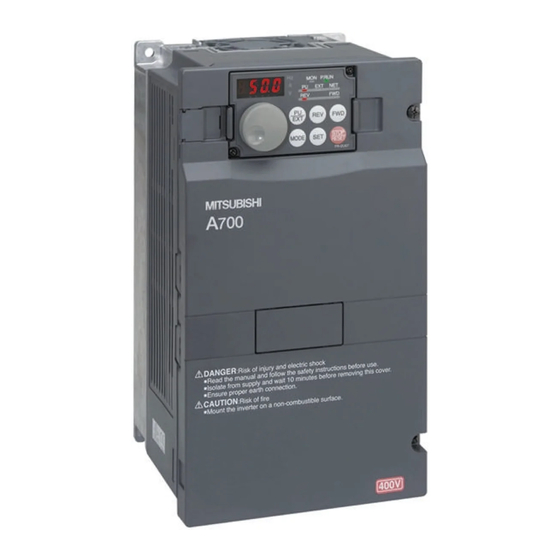
Inverter Type Symbol Voltage Class Symbol Type number Three-phase 00023 A740 400V class 5-digit display 12120 I001410E Fig. 1-1: Inverter type FR-A740 EC FR-A700 EC 1 - 1... -
Page 22: Description Of The Case
Description of the Case Product Checking and Part Identification Description of the Case Cooling fan (refer to section 8.1.7) USB connector (refer to section 6.23.8) PU connector RS-485 terminals (refer to section 3.5) Connector for plug-in option connection (Refer to the instruction manual of options.) Voltage/current input switch (refer to section 3.1) AU/PTC-switchover... -
Page 23: Accessory
For models 01800 or more the supplied DC reactor has to be installed. Eyebolts Two eyebolts (M8) for hanging the inverter are delivered with the models 00770 to 06830. Jumper A jumper is delivered with the model 01800 (refer to section 3.3.1). FR-A700 EC 1 - 3... - Page 24 Description of the Case Product Checking and Part Identification 1 - 4...
-
Page 25: Installation
Remove operation panel Loosen the screws I000991E Fig. 2-1: Removal and reinstallation of the operation panel When reinstalling the operation panel, insert it straight to reinstall securely and tighten the fixed screws of the operation panel. FR-A700 EC 2 - 1... -
Page 26: Removal And Reinstallation Of The Front Cover
Removal and reinstallation of the front cover Installation Removal and reinstallation of the front cover 2.2.1 FR-A740-00023 to 00620-EC Removal Loosen the installation screws of the front cover. Pull the front cover toward you to remove by pushing an installation hook using left fixed hooks as supports. -
Page 27: Fr-A740-00770 To 12120-Ec
Loosen the screw of front Loosen the screw of front Remove front cover cover 1 cover 2 Installation hook Front cover 1 Front cover 2 I000994E Fig. 2-4: Removal of the front cover FR-A700 EC 2 - 3... - Page 28 Removal and reinstallation of the front cover Installation Reinstallation Insert the two fixed hooks on the left side of the front cover 2 into the sockets of the inverter. Using the fixed hooks as supports, securely press the front cover 2 against the inverter. (Although installation can be done with the operation panel mounted, make sure that a connector is securely fixed.) Fix the front cover 2 with the installation screws.
-
Page 29: Mounting
Transportation by holding Oil mist, flammable gas, Mounting to combustible inverters, install them in the front cover corrosive gas, fluff, dust, etc. material parallel.) I000998E Fig. 2-7: Conditions, that could cause an operation fault or failure FR-A700 EC 2 - 5... -
Page 30: Enclosure Design
Enclosure design Installation Enclosure design When an inverter enclosure is to be designed and manufactured, heat generated by contained equipment, etc., the environment of an operating place, and others must be fully considered to determine the enclosure structure, size and equipment layout. The inverter unit uses many semiconductor devices. - Page 31 If the inverter is exposed to corrosive gas or to salt near a beach, the printed board patterns and parts will corrode or the relays and switches will result in poor contact. In such places, take the measures against dust, dirt, oil mist. FR-A700 EC 2 - 7...
- Page 32 Enclosure design Installation Explosive, flammable gases As the inverter is non-explosion proof, it must be contained in an explosion proof enclosure. In places where explosion may be caused by explosive gas, dust or dirt, an enclosure cannot be used unless it structurally complies with the guidelines and has passed the specified tests. This makes the enclosure itself expensive (including the test charges).
- Page 33 Forced ventilation For general indoor installation. Appropriate for enclosure downsizing and cost reduction, and often used. I001003E Heat pipe Totally enclosed type for enclosure downsizing. heat pipe I001004E Tab. 2-2: Cooling system types for inverter enclosure FR-A700 EC 2 - 9...
-
Page 34: Inverter Placement
Enclosure design Installation 2.4.2 Inverter placement Clearances around the inverter Always observe the specified minimum clearances to ensure good heat dissipation and ade- quate accessibility of the frequency inverter for servicing. Ambient temperature and humidity Clearances (side) Clearances (front) Measurement 01800 or less 02160 or more position... - Page 35 (Air passes through areas of low resistance. Make an air- way and airflow plates to expose the inverter to cool air.) Inverter Inverter Good example! Bad example! I001007E Fig. 2-10: Placement of ventilation fan and inverter FR-A700 EC 2 - 11...
-
Page 36: Heatsink Protrusion Attachment (Fr-A7Cn)
Enclosure design Installation 2.4.3 Heatsink protrusion attachment (FR-A7CN) When encasing the inverter in an enclosure, the generated heat amount in an enclosure can be greatly reduced by installing the heatsink portion of the inverter outside the enclosure. When in- stalling the inverter in a compact enclosure, etc., this installation method is recommended. For the FR-A740-00023 to 03610, a heatsink can be protruded outside the enclosure using a heatsink protrusion attachment (FR-A7CN). - Page 37 ● Having a cooling fan, the cooling section which comes out of the enclosure can not be used in the environment of waterdrops, oil, mist, dust, etc. ● Be careful not to drop screws, dust etc. into the inverter and cooling fan section. FR-A700 EC 2 - 13...
- Page 38 Enclosure design Installation 2 - 14...
-
Page 39: Wiring
(ground) cable by Install this as required. Compatible with the 01800 or less. returning it to the earth (ground) terminal of the Compatible with the 02160 or more. inverter. I001435E Fig. 3-1: System configuration overview FR-A700 EC 3 - 1... - Page 40 Inverter and peripheral devices Wiring NOTES Do not install a power factor correction capacitor or surge suppressor on the inverter output side. This will cause the inverter to trip or the capacitor and surge suppressor to be dam- aged. If any of the above devices are connected, immediately remove them. Electromagnetic Compatibility Operation of the frequency inverter can cause electromagnetic interference in the input and output that can be propagated by cable (via the power input lines), by wireless radiation to...
-
Page 41: Peripheral Devices
NF1250 xx 3P 1200 A NF1250 xx 3P 1200 A — FR-A740-10940-EC Rated current 1200 A — NF1600 xx 3P 1500 A NF1600 xx 3P 1600 A — FR-A740-12120-EC Rated current Tab. 3-1: Breakers and contactors FR-A700 EC 3 - 3... - Page 42 Inverter and peripheral devices Wiring Selections for use of the Mitsubishi 4-pole standard motor with power supply voltage of 400V AC 50Hz. Select the MCCB according to the inverter power supply capacity. Install one MCCB per inverter. The places with "xx" refer to the breaking capacity in case of short circuit. The correct selection must be done depending on the design of the power input wiring.
-
Page 43: Terminal Connection Diagram
Option connector 2 It is recommended to use 2W1kΩ Option connector 3 when the frequency setting signal is Terminating changed frequently. (Permissible load resistor current 100 mA) I001436E Fig. 3-3: Terminal connection diagram of the inverter FR-A700 EC 3 - 5... - Page 44 Terminal connection diagram Wiring NOTES To prevent a malfunction due to noise, keep the signal cables more than 10cm away from the power cables. After wiring, wire offcuts must not be left in the inverter. Wire offcuts can cause an alarm, failure or malfunction. Always keep the inverter clean. When drilling mounting holes in an enclosure etc., take care not to allow chips and other for- eign matter to enter the inverter.
-
Page 45: Main Circuit Connection
● The inverter operates only when either a DC reactor or jumper is connected. NOTE When connecting a dedicated brake resistor (FR-ABR) and brake unit (FR-BU, BU) remove jumpers across terminals PR-PX (00250 or less). FR-A700 EC 3 - 7... -
Page 46: Terminal Layout And Wiring
Main circuit connection Wiring 3.3.2 Terminal layout and wiring FR-A740-00023 to 00126-EC FR-A740-00170 and 00250-EC Jumper Screw size M4 CHARGE lamp Jumper Jumper Jumper Screw size M4 CHARGE lamp L1 L2 L3 Screw size M4 Power supply Motor Power supply L1 L2 L3 Screw size M4 Motor... - Page 47 Jumper Screw size M10 Screw size Power supply Motor DC reactor L2 L3 Screw size M12 Power supply Motor (for option) DC reactor Screw size M10 I001437E I001344E Tab. 3-3: Terminal layout and wiring (2) FR-A700 EC 3 - 9...
- Page 48 Main circuit connection Wiring FR-A740-04320 and 04810-EC FR-A740-05470 to 12120-EC Screw size M4 Screw size M4 CHARGE lamp CHARGE lamp Jumper Jumper Screw size M12 Screw size M12 Screw size Power supply Motor Power supply DC reactor Screw size M12 Motor (for option) DC reactor...
- Page 49 Fig. 3-5: Combed shaped wiring cover NOTE Cut off the same numbers of lugs as wires. If you cut off unnecessary parts and no wires are connected, the protective structure (JEM 1030) of the inverter becomes open type (IP00). FR-A700 EC 3 - 11...
- Page 50 Main circuit connection Wiring Cables and wiring length Select the recommended cable size to ensure that a voltage drop will be 2% max. If the wiring distance is long between the inverter and motor, a main circuit cable voltage drop will cause the motor torque to decrease especially at the output of a low frequency.
- Page 51 A screw that has been tighten too tightly can cause a short circuit or malfunction due to the unit breakage. ● Use crimping terminals with insulation sleeve to wire the power supply and motor. FR-A700 EC 3 - 13...
- Page 52 Main circuit connection Wiring Notes on earthing WARNING: Leakage currents flow in the inverter or the EMC filter respectively. To prevent an electric shock, the inverter, input filter and motor must be earthed. (This inverter must be earthed. Earthing must conform to the requirements of national and local safety regulations and electrical codes.
- Page 53 Note that the motor windings are subjected to significantly higher loads when the motor is operated by inverter than with normal mains operation. The motors must be approved for inverter operation by the manufacturer (refer also to section 3.9.5). FR-A700 EC 3 - 15...
-
Page 54: Separate Power Supply For The Control Circuit
Main circuit connection Wiring 3.3.3 Separate power supply for the control circuit In an alarm condition the frequency inverter’s integrated alarm relay only remains active as long as there is a mains power supply on terminals R/L1, S/L2 and T/L3. If you want the alarm signal to remain active after the frequency inverter has been switched off a separate power supply for the control circuit is required, which should be connected as shown in the circuit diagram below. - Page 55 Power supply terminal block for the control circuit Main power supply I001026E Fig. 3-11: Detailed view of the terminals CAUTION: Never connect the power cable to the terminals in the lower stand. Doing so will damage the inverter. FR-A700 EC 3 - 17...
- Page 56 Main circuit connection Wiring Position of the power supply terminal block for the control circuit 00310, 00380 00470, 00620 00770 to 12120 Power supply terminal block for the control circuit I001027E Fig. 3-12: Position of the power supply terminal block for the control circuit CAUTION: ●...
-
Page 57: Control Circuit Specifications
6-286 Note that restart setting is necessary for this instantaneous operation. In the initial setting, a restart is power failure disabled. (Refer to Pr. 57 in section 6.16.) Tab. 3-6: Input signals (1) FR-A700 EC 3 - 19... - Page 58 Control circuit specifications Wiring Rated Terminal Name Description Refer to Specifications A determined control function is activated, if the corresponding terminal is connected to the terminal SD (sink logic). The SD terminal is External transistor isolated from the digital circuits via opto cou- common, contact plers.
- Page 59 Application of voltage with switch on (current input specifica- tion) or current with switch off (voltage input specification) could lead to damage to the inverter or analog circuit of external devices. (For details, refer to section 6.20.2.) FR-A700 EC 3 - 21...
- Page 60 Control circuit specifications Wiring Output signals Rated Terminal Name Description Refer to Specifications Relay output 1 The alarm is output via relay contacts. The A1, B1, C1 6-298 Contact (alarm output) block diagram shows the normal operation and capacity: voltage free status. If the protective function is 230V/0.3A AC activated, the relay picks up.
- Page 61 The FR-Configurator can be performed by connecting the inverter to the personnel computer through USB. — USB connector Interface: Conforms to USB1.1 6-487 Transmission speed: 12Mbps Connector: USB B connector (B receptacle) Tab. 3-8: Communication signals FR-A700 EC 3 - 23...
-
Page 62: Changing The Control Logic
Control circuit specifications Wiring 3.4.1 Changing the control logic The input signals are set to source logic (SOURCE) when shipped from the factory. To change the control logic, the jumper connector on the control circuit terminal block must be moved to the other position. (The output signals may be used in either the sink or source logic independently of the jumper connector position.) I001028E... - Page 63 SINK SOURCE FR-A740 DC input (sink type) FR-A740 DC input (source type) AX40 AX80 Current Current I001029E Fig. 3-14: Changing the control logic FR-A700 EC 3 - 25...
- Page 64 Control circuit specifications Wiring Using an external power supply ● Sink logic type Use terminal PC as a common terminal to prevent a malfunction caused by undesirable current. (Do not connect terminal SD of the inverter with terminal 0V of the external power supply.
-
Page 65: Control Circuit Terminals
Edge thickness: 0,4mm × 2,5mm Tab. 3-9: Connection to the terminals CAUTION: Under tightening can cause cable disconnection or malfunction. Over tightening can cause a short circuit or malfunction due to damage to the screw or unit. FR-A700 EC 3 - 27... - Page 66 Control circuit specifications Wiring Common terminals of the control circuits PC, 5, SE Terminals PC, 5, and SE are all common terminals (0V) for I/O signals and are isolated from each other. Avoid connecting the terminal PC and 5 and the terminal SE and 5. Terminal PC is a common terminal for the contact input terminals (STF, STR, STOP, RH, RM, RL, JOG, RT, MRS, RES, AU, CS).
-
Page 67: Wiring Instructions
Make cuts in rubber bush of the inverter side and lead wires. Wiring Rubber bush (view from the inside) Make cuts along the lines inside with a cutter knife and such. I001022E Fig. 3-21: Wiring of the control circuit of the 02160 or more FR-A700 EC 3 - 29... -
Page 68: Connecting The Operation Panel Using A Connection Cable
Connecting the operation panel using a connection cable Wiring Connecting the operation panel using a connection cable When connecting the operation panel (FR-DU07) to the inverter using a cable, the operation panel can be mounted on the enclosure surface and operationally improves. Fig. -
Page 69: Rs-485 Terminal Block
Tab. 3-10: Specifications of the RS-485 terminal block Terminating resistor switch Factory-set to "OPEN". Set only the terminating resistor switch of the first and the remotest inverter to the "100Ω" position. I001033E Fig. 3-23: RS-485 terminal block FR-A700 EC 3 - 31... -
Page 70: Communication Operation
RS-485 terminal block Wiring 3.6.1 Communication operation Using the PU connector or RS-485 terminal, you can perform communication operation from a personal computer etc. When the PU connector is connected with a personal, FA or other com- puter by a communication cable, a user program can run and monitor the inverter or read and write to parameters. -
Page 71: Usb Communication Specification
Tab. 3-11: USB connector specification USB connector USB cable Removal of cover Place a flat-blade screwdriver, etc. in a slot and push up the cover to open. I001460E Abb. 3-25: Connection to the USB interface FR-A700 EC 3 - 33... -
Page 72: Connection Of Motor With Encoder (Vector Control)
Connection of motor with encoder (vector control) Wiring Connection of motor with encoder (vector control) Following fuctions can be performed by full-scale vector control operation using a motor with en- coder and a plug-in option FR-A7AP. ● Orientation control ● Encoder feedback control ●... - Page 73 If the encoder output type is differential line driver, set the terminating resistor switch to the "OFF" position when sharing the same encoder with other unit (NC (numerical controller), etc) or a terminating resistor is connected to other unit. FR-A700 EC 3 - 35...
- Page 74 Connection of motor with encoder (vector control) Wiring Encoder Specification Terminating Resistor Power Motor Selection Switch Selection Switch Specifications (SW1) (SW2) SF-JR Differential Mitsubishi standard motor SF-HR Differential Mitsubishi high effici- ency motor Others SF-JRCA Differential Mitsubishi constant- SF-HRCA Differential torque motor Others Vector control dedi-...
- Page 75 Wire the stripped cable after twisting it to prevent it from becoming loose. In addition, do not sol- der it. Use a bar terminal as necessary. Fig. 3-30: Cable stripping size I001326E Connection to the option FR-A7AP Motor SF-JR/HR/JRCA/HRCA (with Encoder) Encoder Cable FR-JCBL FR-A7AP-terminal Tab. 3-15: Connection terminal compatibility table FR-A700 EC 3 - 37...
- Page 76 Connection of motor with encoder (vector control) Wiring Wiring ● Speed control Standard motor with encoder (SF-JR), Vector control dedicated motor, 5V differential line driver 12V complimentary Inverter SF-JR motor with encoder Inverter Three-phase AC power supply Earth Forward rotation start Reverse rotation startf Earth Contact input common...
- Page 77 When performing orientation control together, an encoder and power supply can be shared. For terminal compatibility of the FR-JCBL and FR-A7AP, refer to page 3-37. NOTE The figure above shows the connection when using sink logic. FR-A700 EC 3 - 39...
- Page 78 Connection of motor with encoder (vector control) Wiring ● Position control Vector control dedicated motor, 12V complimentary Inverter Positioning unit MELSEC QD75P1 Three-phase AC power supply Earth Forward stroke end Reverse stroke end Pre-excitation/servo on Clear signal Pulse train Sign signal Encoder Differential 24V DC power supply...
- Page 79 (as near as the inverter) with a P clip or U clip made of metal. Fig. 3-31: Earthing (grounding) example using a P clip Encoder cable Shield P clip I001448E NOTE For details of the optional encoder dedicated cable (FR-JCBL), refer to page 3-37. FR-A700 EC 3 - 41...
- Page 80 Connection of motor with encoder (vector control) Wiring Parameter for encoder (Pr. 359, Pr. 369) Initial Pr. No. Name Setting Range Description Value Forward rotation is clockwise rotation when viewed from A. Encoder Encoder rotation direction Forward rotation is counterclockwise rotation when viewed from A.
-
Page 81: Connection Of Stand-Alone Option Units
Since repeated inrush currents at power on will shorten the life of the converter circuit (switching life is about 1,000,000 times.), frequent starts and stops of the MC must be avoided. Turn on/off the inverter start controlling terminals (STF, STR) to run/stop the inverter. FR-A700 EC 3 - 43... - Page 82 Connection of stand-alone option units Wiring Example As shown below, always use the start signal (ON or OFF across terminals STF or STR-PC) to make a start or stop. (Refer to section 6.14.4.) Inverter Power To the supply motor Operation preparation Start-/Stop- Operation Stop...
-
Page 83: Connection Of The Dedicated External Brake Resistor (Fr-Abr)
Connect the brake resistor across terminals P/+ and PR. (The jumper should remain disconnected.) Removal of jumper Connection of Brake Resistor Terminal P/+ Terminal PR Jumper Terminal PR Brake resistor Terminal PX I001451E I001452E Tab. 3-21: Connection of the external brake resistor (00023 to 00126) FR-A700 EC 3 - 45... - Page 84 Connection of stand-alone option units Wiring FR-A740-00170 and 00250 Remove the screws in terminals PR and PX and remove the jumper. Schließen Sie den Bremswiderstand an den Klemmen P/+ und PR an. (Die Brücke muss abgeklemmt bleiben.) Removal of jumper Connection of Brake Resistor Terminal P/+ Terminal PR...
- Page 85 TH-N20CXHZKP-2.5A FR-ABR-H11K on request FR-ABR-H15K on request FR-ABR-H22K on request Tab. 3-24: Combination of resistor and thermal relay Fig. 3-34: Connection of th thermal relay To the inverter P/+ To the brake terminal resistor I001458E FR-A700 EC 3 - 47...
-
Page 86: Connection Of A Brake Unit
Connection of stand-alone option units Wiring 3.8.3 Connection of a brake unit When connecting a brake unit to improve the brake capability at deceleration, make connection as shown below. Connection with the brake unit FR-BU (01800 or less) Inverter 3-phase AC power supply ≤... - Page 87 ● The brake unit which uses multiple resistor units has terminals equal to the number of resistor units. Connect one resistor unit to one pair of terminal (P, PR). FR-A700 EC 3 - 49...
- Page 88 Connection of stand-alone option units Wiring Inserting the CN8 connector Make cuts in the rubber bush for leading the CN8 connector cable with a nipper or cutter knife. Rubber bushes Make cuts in rubber bush I001348E Fig. 3-37: Rubber bush Insert a connector on the MT-BU5 side through a rubber bush to connect to a connector on the inverter side.
-
Page 89: Connection Of The High Power Factor Converter (Fr-Hc, Mt-Hc)
The voltage phases of terminals R/L1, S/L2, T/L3 and terminals R4, S4, T4 must be matched. Use sink logic when the FR-HC is connected. The FR-HC cannot be connected when source logic (factory setting) is selected. FR-A700 EC 3 - 51... - Page 90 Connection of stand-alone option units Wiring Connection with the MT-HC (02160 or more) Inverter 3-phase AC power supply Insulated transformer I001351E Fig. 3-40: Connection with the MT-HC Remove the jumper across terminals R-R1, S-S1 of the inverter, and connect the control circuit power supply to the R1 and S1 terminals.
-
Page 91: Connection Of The Power Regeneration Common Converter Fr-Cv
The voltage phases of terminals R/L11, S/L21, T/MC1 and terminals R2/L1, S2/L2, T2/L3 must be matched. Use sink logic when the FR-CV is connected. The FR-CV cannot be connected when source logic (factory setting) is selected. FR-A700 EC 3 - 53... -
Page 92: Connection Of Power Regeneration Converter (Mt-Rc)
Connection of stand-alone option units Wiring 3.8.6 Connection of power regeneration converter (MT-RC) (02160 or more) When connecting a power regeneration converter (MT-RC), perform wiring securely as shown below. CAUTION: Perform wiring of the power regeneration converter (MT-RC) securely as shown below. Incorrect connection will damage the power regeneration converter and inverter. -
Page 93: Connection Of The Power Improving Dc Reactor Fr-Hel
P-P1. For the 01800 or more, a DC reactor is supplied. Always install the reactor. NOTES The wiring length between the FR-HEL and inverter should be 5m maximum and minimized. Use the same wire size as that of the power supply wire (R/L1, S/L2, T/L3). (Refer to page 3-12). FR-A700 EC 3 - 55... -
Page 94: Electromagnetic Compatibility (Emc)
When the wiring length is long (50m or more) for the small-capacity model (FR-A700-00250 or less), the external thermal relay is likely to operate unnecessarily because the ratio of the leakage current to the rated motor current increases. - Page 95 The earth leakage breaker must be either a Mitsubishi earth leakage breaker (ELB, for har- monics and surges) or an ELB with breaker designed for harmonic and surge suppression that is approved for use with frequency inverters. FR-A700 EC 3 - 57...
- Page 96 Electromagnetic compatibility (EMC) Wiring Note on selecting a suitable power supply ELCB If you install a Mitsubishi frequency inverter with a 3-phase power supply in locations where an earth leakage contact breaker is required by the VDE you must install a universal-current sen- sitive ELCB conforming to the specifications laid down in VDE 0160 / EN 50178 (ELCB Type B).
- Page 97 Input power conditions (400V class: 440V/60Hz, power supply unbalance within 3%) Built-in EMC Filter Voltage [V] ON [mA] OFF [mA] Phase grounding Earth-neutral system Tab. 3-27: Inverter leakage current (with and without built-in EMC filter) FR-A700 EC 3 - 59...
- Page 98 Electromagnetic compatibility (EMC) Wiring NOTES The frequency inverter monitors its own output for ground faults up to a frequency of 120Hz. However, it is important to understand that this feature only protects the inverter itself. It can- not be used to provide protection against shock hazards for personnel. In the connection earthed-neutral system, the sensitivity current is purified against an earth fault in the inverter output side.
-
Page 99: Inverter-Generated Noises And Their Reduction Techniques
– those radiated by the cables connected to the inverter and inverter main circuits (I/O), – those electromagnetically and electrostatically induced to the signal cables of the peripheral devices close to the main circuit power supply, – and those transmitted through the power supply cables. FR-A700 EC 3 - 61... - Page 100 Electromagnetic compatibility (EMC) Wiring Inverter Noise directly radiated Air propagated ... Path generated noise from inverter noise Noise radiated from ... Path power supply cable Noise radiated from mo- ... Path tor connection cable Electromagnetic ... Path induction noise Electrostatic ...
- Page 101 30cm. (at least 10cm) Use a twisted pair shielded cable Power Control supply for Sensor power supply sensor Do not earth shield but connect it to signal common cable. I001050E Fig. 3-49: Noise reduction examples FR-A700 EC 3 - 63...
-
Page 102: Emc Filter
Electromagnetic compatibility (EMC) Wiring 3.9.3 EMC filter The inverter is equipped with a built-in EMC filter and zero-phase reactor. Effective for reduction of air-propagated noise on the input side of the inverter. The EMC filter is factory-set to enable (ON). To disable it, fit the EMC filter ON/OFF connector to the OFF position. The filter must be deactivated when the inverter is used in networks with an isolated neutral (IT networks). -
Page 103: Power Supply Harmonics
For power factor improvement, install a reactor on the inverter input side or in the DC circuit. FR-A700 EC 3 - 65... -
Page 104: Inverter-Driven 400V Class Motor
Electromagnetic compatibility (EMC) Wiring 3.9.5 Inverter-driven 400V class motor In the PWM type inverter, a surge voltage attributable to wiring constants is generated at the mo- tor terminals. Especially for a 400V class motor, the surge voltage may deteriorate the insula- tion. -
Page 105: Operation
Operation Precautions for use of the inverter The FR-A700 series is a highly reliable product, but incorrect peripheral circuit making or op- eration/handling method may shorten the product life or damage the product. Before starting operation, always recheck the following items. - Page 106 Precautions for use of the inverter Operation ● A short circuit or earth fault on the inverter output side may damage the inverter modules. – Fully check the insulation resistance of the circuit prior to inverter operation since repeated short circuits caused by peripheral circuit inadequacy or an earth fault caused by wiring inadequacy or reduced motor insulation resistance may damage the inverter modules.
-
Page 107: Drive The Motor
When protecting the motor from overheat by the inverter, set Pr. 9 "Electronic thermal O/L relay". (Refer to section 5.1.1.) When the rated frequency of the motor is not 50Hz, set Pr. 3 "Base frequency" (Refer to section 5.1.2.) FR-A700 EC 4 - 3... -
Page 108: Operation Panel Fr-Du07
Operation panel FR-DU07 Operation Operation panel FR-DU07 4.3.1 Parts of the operation panel LED-Display 4-digit 7-segment display for opera- tional values, parameter numbers, etc. Unit indication LED to indicate the current unit Frequency Current Voltage Operation mode indication LED to indicate the operation mode PU operation mode (PU) External operation mode (EXT) Network operation mode (NET) - Page 109 Operation mode switch this key to light up the EXT indication. (Change the Pr. 79 value to over use the combined mode.) PU: PU operation mode EXT: External operation mode Tab. 4-1: Keys of the operation panel FR-A700 EC 4 - 5...
-
Page 110: Basic Operation (Factory Setting)
Operation panel FR-DU07 Operation 4.3.2 Basic operation (factory setting) Operation mode switch over At powering on (external operation mode) PU Jog operation mode (Refer to page 4-10.) Example Value change and frequency flicker PU operation mode (output frequency monitor) Frequency setting has been written and completed! Output current monitor Output voltage monitor... -
Page 111: Operation Lock
To make the digital dial and key operation valid again, press the MODE key for 2s. NOTE Set "10 or 11" (key lock mode valid) in Pr. 161 "Frequency setting/key lock operation selec- tion". FR-A700 EC 4 - 7... - Page 112 Operation panel FR-DU07 Operation Operation Display Screen at powering on The monitor display appears. PU indication is lit. Press the PU/EXT key to choose the PU operation mode. The parameter number Press the MODE key to choose the parameter read previously appears.
-
Page 113: Monitoring Of Output Current And Output Voltage
(To return to the output frequency monitor, hold down the SET key for 1s after displaying the out- put frequency monitor.) 4.3.6 Digital dial push Push the digital dial to display the set frequency currently set. Fig. 4-7: Display the set frequency currently set I001067E FR-A700 EC 4 - 9... -
Page 114: Change The Parameter Setting Value
Operation panel FR-DU07 Operation 4.3.7 Change the parameter setting value Example Change the Pr. 1 "Maximum frequency". Operation Display Screen at powering on The monitor display appears. PU indication is lit. Press the PU/EXT key to choose the PU operation mode. The parameter number Press the MODE key to choose the parameter read previously... -
Page 115: Parameter Clear
Fig. 4-9: Parameter clear Possible faults: ● "1" and "Er4" are displayed alternately. – The inverter is not in the PU operation mode. Press the PU/EXT key. The PU indication is lit. Carry out operation from step again. FR-A700 EC 4 - 11... -
Page 116: All Parameter Clear
Operation panel FR-DU07 Operation 4.3.9 All parameter clear ● Set "1" in ALLC "All parameter clear" to initialize all parameters. (Parameters are not cleared when "1" is set in Pr. 77 "Parameter write selection". In addition, calibration parameters are not cleared.) ●... -
Page 117: Parameter Copy An Parameter Verification
Tab. 4-2: Setting of parameter PCPY NOTES When the copy destination inverter is not the FR-A700 series or parameter copy write is per- formed after parameter read is stopped,"model error (rE4)" is displayed. Refer to the extended parameter list Tab. 6-1 for availability of parameter copy. -
Page 118: Parameter Copy
Operation panel FR-DU07 Operation 4.3.11 Parameter copy Multiple inverters and parameter settings can be copied. Operation Display Connect the operation panel to the copy source inverter. Connect it during a stop. The parameter number Press the MODE key to choose the parameter read previously setting mode. - Page 119 ● "rE4" appears. – The copy destination inverter is no FR-A700 model or the parameter write disable function is activated in parameter 77. Set "0" in Pr. 160 "User group read selection" and set Pr. 77 "Parameter write selection" to "0" or "2".
-
Page 120: Parameter Verification
I001116E Fig. 4-12: Parameter verification Possible faults: ● "rE3" appears. – Set frequencies, etc. may be different. Check set frequencies. NOTE When the copy destination inverter is not the FR-A700 series, "model error rE4" is dis- played. 4 - 16... -
Page 121: Basic Settings
(high speed) Set when changing the preset Multi-speed setting 0.01Hz 30Hz 0–400Hz speed in the parameter with a 5-51 (middle speed) terminal. Multi-speed setting 0.01Hz 10Hz 0–400Hz (low speed) Tab. 5-2: Simple mode parameters (1) FR-A700 EC 5 - 1... - Page 122 Simple mode parameter list Basic settings Incre- Initial Refer Name Range Description ments value Acceleration/deceleration time Acceleration time 0.1s 5/15s 0–3600s can be set. Initial values differ according to 5-10 Deceleration time 0.1s 10/30s 0–3600s the inverter capacity. (00250 or less/00310 or more) Protect the motor from overheat by the inverter.
-
Page 123: Overheat Protection Of The Motor By The Inverter
By turning the digital dial, you can read another parameter. Press the SET key to show the setting again. Press the SET key twice to show the next parameter. I001068E Fig. 4-1: Setting of the electronic thermal O/L relay FR-A700 EC 5 - 3... - Page 124 Simple mode parameter list Basic settings NOTES Protective function by electronic thermal relay function is reset by inverter power reset and reset signal input. Avoid unnecessary reset and power-off. When two or more motors are connected to the inverter, they cannot be protected by the electronic thermal relay function.
-
Page 125: When The Rated Motor Frequency Is 60Hz (Pr. 3)
Press the SET key twice to show the next parameter. I001102E Fig. 4-2: Setting the base frequency NOTE Pr. 3 is invalid under advanced magnetic flux vector control, real sensorless vector control, and vector control and Pr. 84 "Rated motor frequency" is valid. FR-A700 EC 5 - 5... -
Page 126: Increase The Starting Torque (Pr. 0)
Simple mode parameter list Basic settings 5.1.3 Increase the starting torque (Pr. 0) Set this parameter when the motor with a load does not rotate, an alarm OL is output, resulting in an inverter trip due to OC1, etc. Setting Name Initial Value Description... - Page 127 (refer to section 6.7.2.) and 81 "Number of motor poles" and activate the real sensorless vector control by Pr. 800. The Pr. 0 setting is invalid under advanced magnetic flux vector control, real sensorless vector control and vector control. FR-A700 EC 5 - 7...
-
Page 128: Limit The Maximum And Minimum Output Frequency (Pr. 1, Pr. 2)
Simple mode parameter list Basic settings 5.1.4 Limit the maximum and minimum output frequency (Pr. 1, Pr. 2) Setting Name Initial Value Description Range 01800 or less 120Hz Set the upper limit of the output Maximum frequency 0–120Hz frequency. 02160 or more 60Hz Set the lower limit of the output Minimum frequency... - Page 129 If the Pr. 2 setting is higher than the Pr. 13 "Starting frequency" value, note that the motor will run at the set frequency according to the acceleration time setting by merely switching the start signal on, without entry of the command frequency. FR-A700 EC 5 - 9...
-
Page 130: Change The Acceleration/Deceleration Time (Pr. 7, Pr. 8)
Simple mode parameter list Basic settings 5.1.5 Change the acceleration/deceleration time (Pr. 7, Pr. 8) Set in Pr. 7 "Acceleration time" a larger value for a slower speed increase and a smaller value for a faster speed increase. Set in Pr. 8 "Deceleration time" a larger value for a slower speed decrease and a smaller value for a faster speed decrease. - Page 131 By turning the digital dial, you can read another parameter. Press the SET key to show the setting again. Press the SET key twice to show the next parameter. I001104E Fig. 5-8: Setting the acceleration time FR-A700 EC 5 - 11...
-
Page 132: Operation Mode (Pr. 79)
Simple mode parameter list Basic settings 5.1.6 Operation mode (Pr. 79) Select the operation command location and frequency command location. LED Indication Initial Setting : OFF Name Description Value Range : ON External operation mode External/PU switch over mode Press the PU/EXT key to switch between the PU and external operation mode. -
Page 133: Large Starting Torque And Low Speed Torque Are Necessary (Advanced Magnetic Flux Vector Control, Real Sensorless Vector Control)
V/f control (advanced magnetic flux vector control) The initial value of the 00023 and 00038 is set to 85% of the rated inverter current. Use Pr. 178 to Pr. 189 to assign the terminals used for the X18 and MC signal. FR-A700 EC 5 - 13... - Page 134 Simple mode parameter list Basic settings If the following conditions are not satisfied, select V/f control since malfunction such as insuffi- cient torque and uneven rotation may occurr. ● The motor capacity should be equal to or one rank lower than the inverter capacity. ●...
- Page 135 When higher accuracy operation is necessary, set online auto tuning after performing offline auto tuning and select real sensorless vector control. Use Pr. 89 to adjust the motor speed fluctuation at load fluctuation. (Refer to section 6.7.2.) FR-A700 EC 5 - 15...
- Page 136 Simple mode parameter list Basic settings Selection method of real sensorless vector control (speed control) Perform secure wiring. (Refer to section 3.2) Set the motor (Pr. 71). (Refer to page 5-13.) Set "3" (standard motor) or "13" (constant-torque motor) in Pr. 71 "Applied motor".
- Page 137 ● For the 00023 to 00126, the speed deviation may become large at 20Hz or less and torque may become insufficient in the low speed region under 1Hz during contin- uous operation under real sensorless vector control. In such case, stop operation once and reaccelerate to improve the problems. FR-A700 EC 5 - 17...
-
Page 138: Higher Accuracy Operation Using A Motor With Encoder (Vector Control) (Pr. 9, Pr. 71, Pr. 80, Pr. 81, Pr. 359, Pr. 369, Pr. 800)
Simple mode parameter list Basic settings 5.1.8 Higher accuracy operation using a motor with encoder (Vector control) (Pr. 9, Pr. 71, Pr. 80, Pr. 81, Pr. 359, Pr. 369, Pr. 800) Vector Vector Vector Full-scale vector control can be performed fitting the FR-A7AP and using a motor with encoder. Fast response/high accuracy speed control (zero speed control, servo lock), torque control, and position control can be performed. - Page 139 V/f control (advanced magnetic flux vector control) The initial value of the 00023 and 00038 is set to 85% of the rated inverter current. Use Pr. 178 to Pr. 189 to assign the terminals used for the X18 and MC signal. FR-A700 EC 5 - 19...
- Page 140 Simple mode parameter list Basic settings If the conditions below are not satisfied, malfunction such as insufficient torque and uneven ro- tation may occur. ● The motor capacity should be equal to or one rank lower than the inverter capacity. ●...
- Page 141 Select online auto tuning as required. (Pr.95) (Refer to section 5.1.10.) Select easy gain tuning as required. (Refer to page 5-33.) Select manual input speed control gain adjustment as required. (Refer to page 5-35.) Fig. 5-11: Selection of speed control FR-A700 EC 5 - 21...
- Page 142 Simple mode parameter list Basic settings Selection method of torque control ● Torque control is exercised to develop torque as set in the torque command. ● The motor speed becomes constant when the motor output torque and load torque are balanced.
- Page 143 Set the electronic gear as required. (Refer to section 6.5.4.) Perform setting of positioning adjustment parameter as required. (Refer to section 6.5.5.) Select gain adjustment of position control as required. (Refer to section 6.5.6.) Fig. 5-13: Selection of position control FR-A700 EC 5 - 23...
-
Page 144: To Exhibit The Best Performance Of The Motor Performance (Offline Auto Tuning) (Pr. 9, Pr. 71, Pr. 83, Pr. 84, Pr. 96)
Simple mode parameter list Basic settings 5.1.9 To exhibit the best performance of the motor performance (offline auto tuning) (Pr. 9, Pr. 71, Pr. 83, Pr. 84, Pr. 96) Magnetic flux Magnetic flux Magnetic flux Sensorless Sensorless Sensorless Vector Vector Vector The motor performance can be maximized with offline auto tuning. - Page 145 01800 or less and sine wave filter connected to the 02160 or more between the inverter and motor. Remove it before starting tuning. ● When exercising vector control, use the encoder that is coupled directly to the motor shaft without looseness. Speed ratio should be 1 : 1. FR-A700 EC 5 - 25...
- Page 146 Simple mode parameter list Basic settings Setting Set "1" or "101" in Pr. 96 "Auto tuning setting/status". ● When the setting is "1" Tuning is performed without motor running. It takes approximately 25 to 120s* until tuning is completed. (Excitation noise is produced during tuning.) (* Tuning time differs according to the inverter capacity and motor type.) ●...
- Page 147 Do not perform ON/OFF switching of the second function selection signal (RT) during execu- tion of offline auto tuning. Auto tuning is not excecuted properly. Setting offline auto tuning (Pr. 96 "Auto tuning setting/status" = 1 or 101) will make pre-exci- tation invalid. FR-A700 EC 5 - 27...
- Page 148 Simple mode parameter list Basic settings Display during tuning Monitor is displayed on the parameter unit (FR-DU07/FR-PU04/FR-PU07) during tuning as be- low. The monitored value is the value of parameter 96.. Parameter unit Parameter unit FR-PU07/FR-PU04 Display FR-DU07 Diesplay Pr. 96 Setting Tuning in progress...
- Page 149 The set frequency monitor displayed during the offline auto tuning is 0Hz. CAUTION: ● Note that the motor may start running suddenly. ● When the offline auto tuning is used in vertical lift application, e.g. a lifter, it may drop due to insufficient torque. FR-A700 EC 5 - 29...
-
Page 150: High Accuracy Operation Unaffected By The Motor Temperature
Simple mode parameter list Basic settings 5.1.10 High accuracy operation unaffected by the motor temperature (online auto tuning) Magnetic flux Magnetic flux Magnetic flux Sensorless Sensorless Sensorless Vector Vector Vector When online auto tuning is selected under advanced magnetic flux vector control, real sensor- less vector control or vector control, excellent torque accuracy is provided by temperature com- pensation even if the secondary resistance value of the motor varies with the rise of the motor temperature. - Page 151 The RUN signal is not output during online auto tuning. The RUN signal turns on at a start. If the period from an inverter stop to a restart is within 4s, start-time tuning is performed but the tuning results are not reflected. FR-A700 EC 5 - 31...
-
Page 152: To Perform High Accuracy / Fast Response Operation (Gain Adjustment Of Real Sensorless Vector Control) (Pr. 818 To Pr. 821, Pr. 880)
Simple mode parameter list Basic settings 5.1.11 To perform high accuracy / fast response operation (gain adjustment of real sensorless vector control) (Pr. 818 to Pr. 821, Pr. 880) Sensorless Sensorless Sensorless Vector Vector Vector The ratio of the load inertia to the motor inertia (load inertia moment ratio) is estimated in real time from the torque command and speed during motor operation by vector control. - Page 153 – No gear backlash nor belt looseness is found. Press the FWD or REV key to estimate the load inertia ratio or calculate gain any time. (The operation command for external operation is the STF or STR signal.) FR-A700 EC 5 - 33...
- Page 154 Simple mode parameter list Basic settings Easy gain tuning execution procedure (Pr. 819 = 2 load inertia manual input) Easy gain tuning (load inertia ratio manual input) is valid only in the speed control under real sen- sorless vector control or in the speed control or position control mode under vector control. Set the load inertia ratio to the motor in Pr.
- Page 155 Also, when there is load inertia, the actual speed gain decreases as indicated below. × -------------------- Actual speed gain speed gain of motor without load JM: Inertia of the motor JL: Motor shaft-equivalent load inertia FR-A700 EC 5 - 35...
- Page 156 Simple mode parameter list Basic settings ● Adjustment procedures are as below: Check the conditions and simultaneously change the Pr. 820 value. If you cannot make proper adjustment, change the Pr. 821 value and repeat the step above. Phenomenon/Condition Adjustment Method Set the Pr.
- Page 157 (5) Encoder power specifications (5) Check the power specifications (5V/12V/ are wrong. Or, power is not 15V/24V) of encoder and input the external input. power supply. Tab. 5-10: Troubleshooting (1) FR-A700 EC 5 - 37...
- Page 158 Simple mode parameter list Basic settings Phenomenon Cause Countermeasures (1) The speed command from the (1) Check that a correct speed command command device is incorrect. comes from the command device. The speed command is com- Decrease Pr. 72 "PWM frequency selec- pounded with noise.
- Page 159 (1) Adverse effect of high carrier (1) Decrease Pr. 72 "PWM frequency selec- Speed fluctuates at low frequency. tion". speed. (2) Low speed control gain. (2) Increase Pr. 820 "Speed control P gain 1". Tab. 5-10: Troubleshooting (3) FR-A700 EC 5 - 39...
-
Page 160: Pu Operation Mode
PU operation mode Basic settings PU operation mode Fig. 5-16: Inverter PU operation mode Power Motor supply I001069E From where is the frequency command given? ● Operation at the frequency set in the frequency setting mode of the operation panel. (Refer to section 5.2.1.) ●... -
Page 161: Set The Set Frequency To Operate
The maximum output frequency is set in Pr. 1. (Refer to section 5.1.4). NOTES Press the digital dial to show the set frequency. The digital dial can also be used like a potentiometer to perform operation. (Refer to section 5.2.2.) FR-A700 EC 5 - 41... -
Page 162: Use The Digital Dial Like A Potentiometer To Perform Operation
PU operation mode Basic settings 5.2.2 Use the digital dial like a potentiometer to perform operation ● Set "1" (setting dial potentiometer mode) in Pr. 161 "Frequency setting/key lock operation selection". Example Change the frequency from 0Hz to 50Hz during operation. Operation Display Screen at powering on... -
Page 163: Use Switches To Give The Frequency Command (Multi-Speed Setting)
Fig. 5-19: Use switches to give the frequency command Speed 1 (high speed) Speed 5 Speed 6 Speed 2 (middle speed) Speed 4 Speed 2 (low speed) Speed 7 I000004aC Fig. 5-20: Multi-speed selection by external terminals FR-A700 EC 5 - 43... - Page 164 PU operation mode Basic settings Operation Display Screen at powering on The monitor display appears. Change the Pr. 79 setting to "4". (Refer to section 4.3.7 for change of the setting.) Press the start switch FWD or REV to give the start command.
-
Page 165: Perform Frequency Setting By Analog Voltage Input
● Use the FWD or REV key to give a start command. The frequency setting potentiometer is supplied with 5V of power from the inverter (terminal 10). Inverter Power Motor supply Frequency setting potentiometer I001075E Fig. 5-22: Frequency setting by analog voltage input FR-A700 EC 5 - 45... - Page 166 PU operation mode Basic settings Operation Display Screen at powering on The monitor display appears. Change the Pr. 79 setting to "4". (Refer to section 4.3.7 for change of the setting.) Press the start key FWD or REV. Operation status indication FWD or REV flickers. CAUTION: When both the forward and reverse key are pushed, the inverter will not start.
-
Page 167: Perform Frequency Setting By Analog Current Input
I001078E Fig. 5-24: Frequency setting by analog current input NOTE Turn the AU signal on to activate the analog current input (0/4 to 20mA). Use a jumper or the like as shown in Fig. 5-24. FR-A700 EC 5 - 47... - Page 168 PU operation mode Basic settings Operation Display Screen at powering on The monitor display appears. Change the Pr. 79 setting to "4". (Refer to section 4.3.7 for change of the setting.) Check that the terminal 4 input selection signal (AU) is on. Press the start key FWD or REV.
-
Page 169: External Operation
● Switch terminal STF (STR)-PC on to give a start command. ● Refer to section 5.2.1 for the set frequency by the operation panel. Inverter Power Motor supply Forward rotation start Reverse rotation start Set frequency I001490E Fig. 5-26: External operation FR-A700 EC 5 - 49... - Page 170 External operation Basic settings Operation Display Screen at powering on The monitor display appears. Change the Pr. 79 setting to "3". (Refer to section 4.3.7 for change of the setting.) Forward Reverse rotation rotation Turn the start switch (STF or STR) on. The motor runs at the frequency set in the set frequency mode of the operation panel.
-
Page 171: Use Switches To Give A Start Command And A Frequency Command (Multi-Speed Setting) (Pr. 4 To Pr. 6)
Fig. 5-28: Frequency and start command by switches Speed 1 (High speed) Speed 5 Speed 6 Speed 2 (Middle speed) Speed 4 Speed 3 (Low speed) Speed 7 I000004aC Fig. 5-29: Multi-speed setting in dependence on the terminals FR-A700 EC 5 - 51... - Page 172 External operation Basic settings Example Set "40Hz" in Pr. 4 "Multi-speed setting (high speed)" and turn on terminals RH and STF (STR)-SD to operate. Operation Display Power on → operation mode check For the initial setting, the inverter operates in the external operation mode "EXT"...
- Page 173 External operation is fixed by setting "2" (external operation mode) in Pr. 79 "Operation mode selection" when you do not want to take time pressing the PU/EXT key or when you want to use the current start command and frequency command. FR-A700 EC 5 - 53...
-
Page 174: Perform Frequency Setting By Analog Voltage Input
External operation Basic settings 5.3.3 Perform frequency setting by analog voltage input The frequency setting potentiometer is supplied with 5V of power from the inverter (terminal 10). Inverter Power Motor supply Forward rotation start Reverse rotation start Frequency setting potentiometer I001090E Fig. - Page 175 Pr. 178 "STF terminal function selection" must be set to "60" (or Pr. 179 "STR terminal func- tion selection" must be set to "61"). (All are initial values.) FR-A700 EC 5 - 55...
- Page 176 External operation Basic settings Possible faults: ● The motor will not rotate. – Check that the EXT lamp is lit. The external operation mode is valid when Pr. 79 = 0 (initial value) or "2". Use the PU/EXT key to change into the external operation mode. –...
-
Page 177: Change The Frequency (50Hz) Of The Maximum Value Of Potentiometer (At 5V)
As other adjustment methods of frequency setting voltage gain, there are methods to adjust with a voltage applied to across terminals 2-5 and adjust at any point without a voltage applied. (Refer to section 6.20.5 for the setting method of calibration parameter C4.) FR-A700 EC 5 - 57... -
Page 178: Perform Frequency Setting By Analog Current Input
External operation Basic settings 5.3.5 Perform frequency setting by analog current input ● Switch terminal STF (STR)-PC on to give a start command. ● Turn the AU signal on. ● Pr. 79 "Operation mode selection" must be set to "2" (external operation mode). Inverter Power Motor... - Page 179 – Check that wiring is correct. Check once again. NOTE Change the frequency (0Hz) of the minimum value of potentiometer (at 4mA, initial value) by adjusting the frequency in calibration parameter C5 "Terminal 4 frequency setting bias fre- quency". (Refer to section 6.20.5.) FR-A700 EC 5 - 59...
-
Page 180: Change The Frequency (50Hz) Of The Maximum Value Of Potentiometer (At 20Ma)
External operation Basic settings 5.3.6 Change the frequency (50Hz) of the maximum value of potentiometer (at 20mA) Example The frequency of the maximum analog current of the potentiometer (at 20mA) has to be changed from the initial setting of 50Hz to 40 Hz. Set 40Hz in Pr. 126. Operation Display Turn the digital dial until P.126 (Pr. -
Page 181: Parameter
Set when performing operation at 120 Hz or more High speed maximum 120/ ✔ ✔ ✔ 0.01Hz 120–400Hz * The setting depends on the 60Hz * frequency inverter capacity: (01800 or less/02160 or more) Tab. 6-1: Parameter overview (1) FR-A700 EC 6 - 1... - Page 182 Parameter overview Parameter Para- Para- para- Parameter meter meter meter copy clear Refer clear Func- Incre- Initial Setting Name Description tion ments Value Range page ✔: enabled —: disabled Set the frequency when the motor ✔ ✔ ✔ Base frequency 0.01Hz 50Hz 0–400Hz...
- Page 183 9999 Function invalid Set the deceleration time when the 0–3600/ 360s X9 signal is on. 0.1/ ✔ ✔ ✔ Third deceleration time 9999 0.01s Acceleration time = deceleration 9999 time Tab. 6-1: Parameter overview (3) FR-A700 EC 6 - 3...
- Page 184 Parameter overview Parameter Para- Para- para- Parameter meter meter meter copy clear Refer clear Func- Incre- Initial Setting Name Description tion ments Value Range page ✔: enabled —: disabled Set the rated motor current. Rated Electronic thermal O/L * The setting depends on the 0.01/ inverter 0–500/...
- Page 185 6-290 input (NC contact input specifica- tions) Communication: Normally open input Refer to Pr. 1 and Pr. 2 Refer to Pr. 3 — Refer to Pr. 7 and Pr. 8 Tab. 6-1: Parameter overview (5) FR-A700 EC 6 - 5...
- Page 186 Parameter overview Parameter Para- Para- para- Parameter meter meter meter copy clear Refer clear Func- Incre- Initial Setting Name Description tion ments Value Range page ✔: enabled —: disabled Stall prevention operation selection becomes invalid. Function as stall prevention opera- tion under V/f control and Stall prevention ✔...
- Page 187 Torque limit based on the analog input from terminal 1 and 4. Running Torque limit speed increments increments Set resolution 1r/min ✔ ✔ ✔ 0.1% increments switchover 0.1r/min 1r/min 0.01% incre- ments 0.1r/min Tab. 6-1: Parameter overview (7) FR-A700 EC 6 - 7...
- Page 188 Parameter overview Parameter Para- Para- para- Parameter meter meter meter copy clear Refer clear Func- Incre- Initial Setting Name Description tion ments Value Range page ✔: enabled —: disabled Set the torque limit level for for- 0–400% Torque limit level ward rotation regeneration.
- Page 189 S-pattern time at a ✔ ✔ ✔ acceleration/deceleration (S-pat- 0.1s 0.1s 0.1–2.5s start of deceleration tern operation). S-pattern time at a ✔ ✔ ✔ completion of deceler- 0.1s 0.1s 0.1–2.5s ation Tab. 6-1: Parameter overview (9) FR-A700 EC 6 - 9...
- Page 190 Parameter overview Parameter Para- Para- para- Parameter meter meter meter copy clear Refer clear Func- Incre- Initial Setting Name Description tion ments Value Range page ✔: enabled —: disabled External brake unit FR-BU and external brake resistor unit FR-BR External brake unit MT-BU5, —...
- Page 191 Refer to Pr. 7 and Pr. 8 Refer to Pr. 0 — Refer to Pr. 3 Refer to Pr. 22 and Pr. 23 Refer to Pr. 41 to Pr. 43 — Refer to Pr. 9 Tab. 6-1: Parameter overview (11) FR-A700 EC 6 - 11...
- Page 192 Parameter overview Parameter Para- Para- para- Parameter meter meter meter copy clear Refer clear Func- Incre- Initial Setting Name Description tion ments Value Range page ✔: enabled —: disabled 0/5–14/ Select monitor to be displayed on 17–20/ the operation panel and parameter DU/PU main display ✔...
- Page 193 ✔ ✔ AM output filter 0.01s 0.01s 0–5s Set the output filter of terminal AM. Adjust response level of current ✔ ✔ ✔ Current output filter 0.01s 0.02s 0–5s output. Tab. 6-1: Parameter overview (13) FR-A700 EC 6 - 13...
- Page 194 Parameter overview Parameter Para- Para- para- Parameter meter meter meter copy clear Refer clear Func- Incre- Initial Setting Description Name tion ments Value Range page ✔: enabled —: disabled The coasting time is as follows: 00052 or less:...... 0.5s, 00083–00250: ......1s, 00310–01800: .....
- Page 195 Reference value at ✔ ✔ ✔ 0.1% 9999 deceleration 150% is a Shortest decelera- limit value tion time 9999 Pr. 61 is the Optimum reference deceleration value Tab. 6-1: Parameter overview (15) FR-A700 EC 6 - 15...
- Page 196 Parameter overview Parameter Para- Para- para- Parameter meter meter meter copy clear Refer clear Func- Incre- Initial Setting Name Description tion ments Value Range page ✔: enabled —: disabled 0–10Hz 0 to 10Hz are starting frequency Starting frequency for ✔ ✔...
- Page 197 (SF-JR 4P 1.5kW or less) Auto tuning data Mitsubishi can be read, vector motor changed, and set. (SF-V5RU/ SF-THY) Mitsubishi high efficiency motor (SF-HR) Mitsubishi constant- torque motor (SF-HRCA) Tab. 6-1: Parameter overview (17) FR-A700 EC 6 - 17...
- Page 198 Parameter overview Parameter Para- Para- para- Parameter meter meter meter copy clear Refer clear Func- Incre- Initial Setting Name Description tion ments Value Range page ✔: enabled —: disabled Standard Star connection motor Direct input of motor constants Constant- is enabled torque motor Standard Delta connection...
- Page 199 2mA, the LF signal is output and inverter continues operation at 4mA input check ✔ ✔ ✔ 9999 the frequency (average value) just selection before current reaches 2mA. 9999 4mA input is not checked. Tab. 6-1: Parameter overview (19) FR-A700 EC 6 - 19...
- Page 200 Parameter overview Parameter Para- Para- para- Parameter meter meter meter copy clear Refer clear Func- Incre- Initial Setting Name Description tion ments Value Range page ✔: enabled —: disabled The primary delay filter time con- stant for the analog input can be Input filter time ✔...
- Page 201 10/12 When the setting is "12", it will resume the preinstantaneous power failure operation mode after an instantaneous power failure occurs. Tab. 6-1: Parameter overview (21) FR-A700 EC 6 - 21...
- Page 202 Parameter overview Parameter Para- Para- para- Parameter meter meter meter copy clear Refer clear Func- Incre- Initial Setting Name Description tion ments Value Range page ✔: enabled —: disabled Set the applied motor capacity. * The increments and setting 0.4–55kW/ range differ according to the 0.01kW/ 0–3600kW *...
- Page 203 Speed control Torque con- trol Real sensorless MC signal- vector control ON: torque MC signal- OFF: speed V/f Control (advanced magnetic flux vector control) Tab. 6-1: Parameter overview (23) FR-A700 EC 6 - 23...
- Page 204 Parameter overview Parameter Para- Para- para- Parameter meter meter meter copy clear Refer clear Func- Incre- Initial Setting Name Description tion ments Value Range page ✔: enabled —: disabled Tuning data (The value measured by offline auto tuning is automatically set.) 0–500A/ * The increments and setting 0–3600A *...
- Page 205 Second motor constant 0.001Ω/ range differ according to the ✔ ✔ 9999 — 0.01mΩ * (R2) inverter capacity. (01800 or less/02160 or more) Use the Mitsubishi motor (SF-JR, 9999 SF-HRCA) constants Tab. 6-1: Parameter overview (25) FR-A700 EC 6 - 25...
- Page 206 Parameter overview Parameter Para- Para- para- Parameter meter meter meter copy clear Refer clear Func- Incre- Initial Setting Name Description tion ments Value Range page ✔: enabled —: disabled Tuning data of the second motor (The value measured by offline 0–50Ω...
- Page 207 ✔ ✔ 0.1V 0–1000V voltage) Refer to page 6-15 Refer to Pr. 7 Refer to Pr. 0 — Refer to Pr. 3 Refer to Pr. 22 Refer to Pr. 41 Tab. 6-1: Parameter overview (27) FR-A700 EC 6 - 27...
- Page 208 Parameter overview Parameter Para- Para- para- Parameter meter meter meter copy clear Refer clear Func- Incre- Initial Setting Name Description tion ments Value Range page ✔: enabled —: disabled Specify the inverter station number. Set the inverter station PU communication ✔...
- Page 209 (com- change, reset puter link) (switch power off, protocol then on) the ✔ ✔ ✔ Protocol selection inverter. The set- ting change is Modbus-RTU reflected after a protocol reset. Tab. 6-1: Parameter overview (29) FR-A700 EC 6 - 29...
- Page 210 Parameter overview Parameter Para- Para- para- Parameter meter meter meter copy clear Refer clear Func- Incre- Initial Setting Name Description tion ments Value Range page ✔: enabled —: disabled Terminal 2 frequency Set the frequency of terminal 2 ✔ ✔ 0.01Hz 50Hz 0–400Hz...
- Page 211 (Not reflected to PID forward the inverter fre- action quency) PID reverse Measured value, action set point input (PLC function) (Not reflected to PID forward the inverter fre- action quency) Tab. 6-1: Parameter overview (31) FR-A700 EC 6 - 31...
- Page 212 Parameter overview Parameter Para- Para- para- Parameter meter meter meter copy clear Refer clear Func- Incre- Initial Setting Name Description tion ments Value Range page ✔: enabled —: disabled If the proportional band is narrow (parameter setting is small), the manipulated variable varies greatly with a slight change of the meas- ured value.
- Page 213 – Refer to Pr. 29 — Refer to Pr. 37 Tab. 6-1: Parameter overview (33) FR-A700 EC 6 - 33...
- Page 214 Parameter overview Parameter Para- Para- para- Parameter meter meter meter copy clear Refer clear Func- Incre- Initial Setting Name Description tion ments Value Range page ✔: enabled —: disabled Japanese English German French PU display language ✔ — — 6-537 selection Spanish Italian...
- Page 215 Setting dial potentiome- ter mode – Refer to Pr. 57 Refer to Pr. 150 — Parameter for manufacturer setting. Do not set. Refer to Pr. 52 – Refer to Pr. 160 Tab. 6-1: Parameter overview (35) FR-A700 EC 6 - 35...
- Page 216 Parameter overview Parameter Para- Para- para- Parameter meter meter meter copy clear Refer clear Func- Incre- Initial Setting Name Description tion ments Value Range page ✔: enabled —: disabled 0–20/ 0: Low-speed operation 22–28/37/ command STF terminal function ✔ ✔ 42–44/50/ —...
- Page 217 — 194–196/ 98/198: Minor fault output tion selection 198/199/ 99/199: Alarm output 9999 9999: No function 0–99: Source logic 100–199: Sink logic * Available only when used with the FR-A7AP Tab. 6-1: Parameter overview (37) FR-A700 EC 6 - 37...
- Page 218 Parameter overview Parameter Para- Para- para- Parameter meter meter meter copy clear Refer clear Func- Incre- Initial Setting Name Description tion ments Value Range page ✔: enabled —: disabled – Refer to Pr. 4 to Pr. 6 Refer to Pr. 72 —...
- Page 219 When the Pr. 259 value is "3" after life measuring powering on again, the measuring is completed. Read the deteriora- tion degree in Pr. 258. — Refer to Pr. 72 Tab. 6-1: Parameter overview (39) FR-A700 EC 6 - 39...
- Page 220 Parameter overview Parameter Para- Para- para- Parameter meter meter meter copy clear Refer clear Func- Incre- Initial Setting Name Description tion ments Value Range page ✔: enabled —: disabled Coasting to stop When under voltage or power fail- ure occurs, the inverter output is shut off.
- Page 221 * The setting range differs ✔ ✔ ✔ quency at stopon con- 9999 according to the inverter tact capacity. (01800 or less/02160 or more) As set in Pr. 72 "PWM frequency 9999 selection". Tab. 6-1: Parameter overview (41) FR-A700 EC 6 - 41...
- Page 222 Parameter overview Parameter Para- Para- para- Parameter meter meter meter copy clear Refer clear Func- Incre- Initial Setting Name Description tion ments Value Range page ✔: enabled —: disabled Set to the rated slip frequency of Brake opening fre- the motor + about 1.0Hz. This ✔...
- Page 223 0–400Hz input pulse pulse is 0 (bias). Frequency for maxi- Set the frequency when the input ✔ ✔ ✔ 0.01Hz 50 Hz 0–400Hz mum input pulse pulse is maximum (gain). Tab. 6-1: Parameter overview (43) FR-A700 EC 6 - 43...
- Page 224 Parameter overview Parameter Para- Para- para- Parameter meter meter meter copy clear Refer clear Func- Incre- Initial Setting Name Description tion ments Value Range page ✔: enabled —: disabled — Refer to Pr. 61 — Refer to Pr. 261 Refer to Pr. 57 —...
- Page 225 Encoder Clockwise direction as viewed from A is forward rotation Encoder rotation ✔ ✔ ✔ direction Encoder Counterclockwise direction as viewed from A is forward rotation Tab. 6-1: Parameter overview (45) FR-A700 EC 6 - 45...
- Page 226 Parameter overview Parameter Para- Para- para- Parameter meter meter meter copy clear Refer clear Func- Incre- Initial Setting Name Description tion ments Value Range page ✔: enabled —: disabled Speed com- mand When 1 is set in Position com- Pr. 350 and the mand 16 bit option FR-A7AX is data is used...
- Page 227 Overspeed detection ✔ ✔ ✔ 0.01Hz 140Hz 0–400Hz real sensorless vector control, or 6-357 level vector control, over speed (E.OS) occurs and stops the inverter out- put. Tab. 6-1: Parameter overview (47) FR-A700 EC 6 - 47...
- Page 228 Parameter overview Parameter Para- Para- para- Parameter meter meter meter copy clear Refer clear Func- Incre- Initial Setting Name Description tion ments Value Range page ✔: enabled —: disabled Signal loss detection is invalid Signal loss detection is valid When the cable of the encoder sig- Open cable detection nal is broken during encoder feed- ✔...
- Page 229 Enters the primary delay filter in Position feed forward ✔ ✔ ✔ 0.001s 0–5s response to the feed forward com- command filter mand. Tab. 6-1: Parameter overview (49) FR-A700 EC 6 - 49...
- Page 230 Parameter overview Parameter Para- Para- para- Parameter meter meter meter copy clear Refer clear Func- Incre- Initial Setting Name Description tion ments Value Range page ✔: enabled —: disabled The in-position signal (Y36) turns 0–32767 ✔ ✔ ✔ In-position width 1 pulse on when the droop pulses become pulses...
- Page 231 4 digits Ninth position feed ✔ ✔ ✔ 0–9999 amount lower 4 digits Speed 9 REX, RL (Pr. 233) Ninth position feed ✔ ✔ ✔ 0–9999 amount upper 4 digits Tab. 6-1: Parameter overview (51) FR-A700 EC 6 - 51...
- Page 232 Parameter overview Parameter Para- Para- para- Parameter meter meter meter copy clear Refer clear Func- Incre- Initial Setting Name Description tion ments Value Range page ✔: enabled —: disabled Tenth position feed ✔ ✔ ✔ 0–9999 amount lower 4 digits Speed 10 REX, RM (Pr.
- Page 233 ✔ ✔ monitor signal output inverter * Setting increments and setting 0.1A * 0–3600A * current reference current range differ according to the inverter capacity: (01800 or less/02160 or more) Tab. 6-1: Parameter overview (53) FR-A700 EC 6 - 53...
- Page 234 Parameter overview Parameter Para- Para- para- Parameter meter meter meter copy clear Refer clear Func- Incre- Initial Setting Name Description tion ments Value Range page ✔: enabled —: disabled Refer to Pr. 52 — Refer to Pr. 80 Ambient temperature 40°C, Overload current rating 110% 60s, 120% 3s (Inverse time characteristics)
- Page 235 (valid when Pr. 807 = 1) Reverse rotation speed ✔ ✔ ✔ 0.01Hz 9999 limit The setting is the same as that of 9999 the torque limit in the forward rotation direction. Tab. 6-1: Parameter overview (55) FR-A700 EC 6 - 55...
- Page 236 Parameter overview Parameter Para- Para- para- Parameter meter meter meter copy clear Refer clear Func- Incre- Initial Setting Name Description tion ments Value Range page ✔: enabled —: disabled Refer to Pr. 22 Refer to Pr. 22 and Pr. 37 —...
- Page 237 1 current feedback. Second function of Pr. 827 (valid 0–0.1s when the RT signal is on) 6-144 Torque detection ✔ ✔ ✔ 0.001s 9999 filter 2 9999 No function Tab. 6-1: Parameter overview (57) FR-A700 EC 6 - 57...
- Page 238 Parameter overview Parameter Para- Para- para- Parameter meter meter meter copy clear Refer clear Func- Incre- Initial Setting Name Description tion ments Value Range page ✔: enabled —: disabled Model speed control Set the gain for model speed ✔ ✔ ✔...
- Page 239 Same as at a rise time (C18, C19). Refer to Pr. 74 — Refer to Pr. 10 Refer to Pr. 285 Set the excitation ratio under no ✔ ✔ ✔ Excitation ratio 100% 0–100% 6-146 load. Tab. 6-1: Parameter overview (59) FR-A700 EC 6 - 59...
- Page 240 Parameter overview Parameter Para- Para- para- Parameter meter meter meter copy clear Refer clear Func- Incre- Initial Setting Name Description tion ments Value Range page ✔: enabled —: disabled Frequency/speed command Magnetic flux command Terminal 4 function ✔ ✔ — assignment Stall prevention/torque limit 9999...
- Page 241 Pr. 886 setting. When vibration is not suppressed by decreasing the Pr. 886 setting, set a smaller value in Pr. 665. Tab. 6-1: Parameter overview (61) FR-A700 EC 6 - 61...
- Page 242 Parameter overview Parameter Para- Para- para- Parameter meter meter meter copy clear Refer clear Func- Incre- Initial Setting Name Description tion ments Value Range page ✔: enabled —: disabled Parameters you can use for your own purposes ✔ Free parameter 1 9999 0–9999 —...
- Page 243 Set the converted % of the gain Terminal 1 gain ✔ ✔ 0.1% 100% 0–300% side voltage (current) of terminal 1 — (920) (torque/magnetic flux) input. (valid when Pr. 868 ≠ 0, 5) Tab. 6-1: Parameter overview (63) FR-A700 EC 6 - 63...
- Page 244 Parameter overview Parameter Para- Para- para- Parameter meter meter meter copy clear Refer clear Func- Incre- Initial Setting Name Description tion ments Value Range page ✔: enabled —: disabled Set the torque/magnetic flux com- Terminal 4 bias com- mand value on the bias side of ter- ✔...
-
Page 245: Control Mode
– To prevent machine from damage due to too large torque (torque limit) – To perform torque control or position control – Servo-lock torque control which generates a torque at zero speed (i.e. status of motor shaft = stopped) FR-A700 EC 6 - 65... -
Page 246: What Is Vector Control
Control mode Parameter 6.2.1 What is vector control? Vector control is one of the control techniques for driving an induction motor. To help explain vector control, the fundamental equivalent circuit of an induction motor is shown below: Fig. 6-1: Equivalent circuit of an induction motor I001497E r1: Primary resistance r2: Secondary resistance... - Page 247 ● Allows torque control. ● Allows servo-lock torque control which generates a torque at zero speed (i.e. status of motor shaft = stopped). (Cannot be performed under real sensorless vector control.) FR-A700 EC 6 - 67...
- Page 248 Control mode Parameter Block diagram of real sensorless vector control modulation magnetic pre-excitation flux current output control control voltage conversion torque speed current control control current conversion slip calculation calculation flux magnetic speed estimation I001499E Fig. 6-3: Block diagram of real sensorless vector control Block diagram of vector control Encoder modulation...
- Page 249 (φ2). The output frequency is found by adding that slip (ωs) to the feedback (ωFB) found by a feedback from the encoder. The above results are used to make PWM modulation and run the motor. FR-A700 EC 6 - 69...
-
Page 250: Change The Control Method (Pr. 80, Pr. 81, Pr. 451, Pr. 800)
Control mode Parameter 6.2.2 Change the control method (Pr. 80, Pr. 81, Pr. 451, Pr. 800) Set when selecting the advanced magnetic flux vector control, real sensorless vector control or vector control. Select a control mode from speed control mode, torque control mode and posi- tion control mode under real sensorless vector control or vector control. - Page 251 Since current is not detected and voltage is not output, monitors related to current and volt- age such as output current and output voltage, etc. and output signals do not function. For speed calculation, speed is calculated in consideration of Pr. 880 "Load inertia ratio". FR-A700 EC 6 - 71...
- Page 252 Control mode Parameter Control method switching by external terminals (RT signal, X18 signal) ● The switching of the control method (V/f control, advanced magnetic flux vector control, real sensorless vector control and vector control) by the external terminal may be made in either of the following two ways: switching by the second function selection signal (RT), or V/f switching signal (X18).
- Page 253 Regenerative torque limit (Pr. 810 = 1) — — Torque limit (Pr. 810 = 1) Torque limit (Pr. 810 = 1) — — Torque bias — 9999 — — Tab. 6-5: Terminal 1 function when Pr. 800 = 4 FR-A700 EC 6 - 73...
- Page 254 Control mode Parameter Vector Control (Pr. 800 = 5) Pr. 868 Position control (MC signal-OFF) Torque control (MC signal-ON) 0 (initial value) — Speed setting auxiliary Magnetic flux command Magnetic flux command Regenerative torque limit (Pr. 810 = 1) — —...
- Page 255 Pr. 865 "Low speed detection", and not switched during motor operation. Changing the terminal assignment using Pr. 178 to Pr. 189 "Input terminal function selec- tion" may affect the other functions. Please make setting after confirming the function of each terminal. FR-A700 EC 6 - 75...
-
Page 256: Speed Control By Real Sensorless Vector Control, Vector Control
Speed control by real sensorless vector control, vector control Parameter Speed control by real sensorless vector control, vector control Speed control is exercised to match the speed command and actual motor speed. Refer to Purpose Parameter that should be Set Section To perform torque limit during speed Torque limit... -
Page 257: Selection Method Of Real Sensorless Vector Control (Speed Control)
Select online auto tuning as required. (Pr. 95) (Refer to page 6-89.) Select easy gain tuning as required. (Refer to section 6.12.4.) Select manual input speed control gain adjustment as required. (Refer to page 6-92.) Fig. 6-5: Selection of the real sensorless vector control (speed control) FR-A700 EC 6 - 77... - Page 258 Speed control by real sensorless vector control, vector control Parameter NOTES Make sure to perform offline auto tuning before performing real sensorless vector control. The carrier frequencies are selectable from among 2k, 6k, 10k, 14kHz for real sensorless vector control. Torque control can not be performed in the low speed region and at a low speed with light load.
- Page 259 Select manual input speed control gain adjustment as required. (Refer to page 6-92.) Fig. 6-6: Selection of vector control (speed control) NOTE The carrier frequencies are selectable from among 2k, 6k, 10k, 14kHz for vector control. FR-A700 EC 6 - 79...
-
Page 260: Torque Limit Level Setting For Speed Control (Pr. 22, Pr. 803, Pr. 810 To Pr. 817, Pr. 858, Pr. 868, Pr. 874)
Speed control by real sensorless vector control, vector control Parameter 6.3.2 Torque limit level setting for speed control (Pr. 22, Pr. 803, Pr. 810 to Pr. 817, Pr. 858, Pr. 868, Pr. 874) Sensorless Sensorless Sensorless Vector Vector Vector This function limits the output torque to the predetermined value during speed control under real sensorless vector control or vector control. - Page 261 OLT level setting 150% 0–200% to stall the motor. Set the output at which an alarm stop is made. Setting can be made only when the FR-A7AP is mounted. FR-A700 EC 6 - 81...
- Page 262 Speed control by real sensorless vector control, vector control Parameter Torque limit block diagram <Vector control> Torque limit Speed control Iq current control Speed command Encoder I001501E Fig. 6-7: Torque limit block diagram Selection of torque limit input method (Pr. 810) Set Pr.
- Page 263 Terminal 4 input or internal torque limit Terminal 1 input or internal torque limit (Pr. 22 etc.) whichever is smaller (Pr. 22 etc.) whichever is smaller Reverse Forward driving regeneration Rated speed I001504E Fig. 6-10: Torque limit level by analog input FR-A700 EC 6 - 83...
- Page 264 Speed control by real sensorless vector control, vector control Parameter Real Sensorless Vector Control (Speed Control) Pr. 858 Pr. 868 Terminal 4 function Terminal 1 function Speed setting auxiliary (initial value) Magnetic flux command — — Speed command Torque limit (initial value) (AU signal-ON) (Pr.
- Page 265 (Pr. 816 or Pr. 817) shifts to torque limit level during constant speed (Pr. 22). frequency Time Acceleration Constant speed Deceleration I001506E Fig. 6-12: Individual torque limit value during acceleration and deceleration FR-A700 EC 6 - 85...
- Page 266 Speed control by real sensorless vector control, vector control Parameter Setting increments switchover of the torque limit level (Pr. 811) By setting "10, 11" in Pr. 811 "Set resolution switchover", the setting increments of Pr. 22 "Torque limit level" and Pr. 812 to Pr. 817 "Torque limit level" can be switched to 0.01%. NOTES The internal resolution of the torque limit is 0.024% (100/2 ) and the fraction less than the...
- Page 267 (E.OLT) appears to shutoff the inverter output. In this case, this function is activated regardless of Pr. 874. This alarm is not provided under torque control. FR-A700 EC 6 - 87...
-
Page 268: To Perform High Accuracy/Fast Response Operation
Speed control by real sensorless vector control, vector control Parameter 6.3.3 To perform high accuracy/fast response operation (gain adjustment of real sensorless vector control and vector control) (Pr. 818 to Pr. 821, Pr. 830, Pr. 831, Pr. 880) Sensorless Sensorless Sensorless Vector Vector... - Page 269 Actual motor speed Gain table Pr. 880 estimation section Speed/position feedback Easy gain tuning Easy gain tuning selection (Pr. 819 ) response level setting (Pr. 818 ) I001509E Fig. 6-15: Block diagram of easy gain tuning function FR-A700 EC 6 - 89...
- Page 270 Speed control by real sensorless vector control, vector control Parameter Easy gain tuning execution procedure (Pr. 819 = 1 load inertia ratio automatic estimation) Easy gain tuning (load inertia ratio automatic estimation) is valid only in the speed control or position control mode under vector control.
- Page 271 In addition, when the motor shaft is fixed with servo lock or position control, bearing may be damaged. To prevent these, make gain adjustment by manual input without performing easy gain tuning. FR-A700 EC 6 - 91...
- Page 272 Speed control by real sensorless vector control, vector control Parameter Manual input speed control gain adjustment Make adjustment when any of such phenomena as unusual machine vibration/noise, low response level and overshoot has occurred. ● Pr. 820 "Speed control P gain 1" = 60% (initial value) is equivalent to 120rad/s (speed response of the motor alone).
- Page 273 Pr. 830 "Speed control P gain 2" and Pr. 831 "Speed control integral time 2" are made valid when the RT terminal is switched on. Make adjustments in the same way as Pr. 820 and Pr. 821. FR-A700 EC 6 - 93...
- Page 274 Speed control by real sensorless vector control, vector control Parameter When using a multi-pole motor (8 poles or more) Specially when using a multi-pole motor with more than 8 poles under vector control (with encoder, real sensorless), adjust speed control P gain (Pr. 820) and torque control P gain (Pr. 824) according to the motor referring to the following methods.
- Page 275 I001510E Fig. 6-18: Function block diagram] NOTE Changing the terminal assignment using Pr. 178 to Pr. 189 "Input terminal function selection" may affect the other functions. Make setting after confirming the function of each terminal. FR-A700 EC 6 - 95...
- Page 276 Speed control by real sensorless vector control, vector control Parameter Troubleshooting Phenomenon Cause Countermeasures (1) The motor wiring is wrong (1) Wiring check Select V/f control (Pr. 800 = 20) and check the rotation direction of the motor. Check the speed monitor output from out- put terminal CA.
- Page 277 (2) The torque control gain is high. (2) Decrease the Pr. 824 value. (Refer to sec- tion 6.4.7.) (3) The motor wiring is wrong. (3) Check the wiring. Tab. 6-16: Troubleshooting (2) FR-A700 EC 6 - 97...
- Page 278 Speed control by real sensorless vector control, vector control Parameter Phenomenon Cause Countermeasures (1) Insufficient torque. (1)-1 Increase the torque limit value. (Refer to torque limit of speed control in section Acceleration/deceleration 6.3.2.) time does not match the (1)-2 Perform speed feed foward control. setting.
-
Page 279: (Pr. 828, Pr. 877 To Pr. 881)
(J : Pr. 880) Speed command Speed control iqcurrent P gain 1 control Pr. 820 Speed control Actual speed integral time 1 controller Pr. 821 Pr. 877 Speed estimator I001511E Fig. 6-19: Block diagram FR-A700 EC 6 - 99... - Page 280 Speed control by real sensorless vector control, vector control Parameter Speed feed forward control (Pr. 877 = 1) ● Calculate required torque in responce to the acceleration/deceleration command for the inertia ratio set in Pr. 880 and generate torque immediately. ●...
- Page 281 Tuning results are dis- Tuning results are dis- (Pr. 828) played. played. Write disabled Write disabled Speed feed forward gain Manual input Manual input Manual input (Pr. 881) Tab. 6-17: Combination of easy gain tuning FR-A700 EC 6 - 101...
-
Page 282: Torque Biases (Pr. 840 To Pr. 848)
Speed control by real sensorless vector control, vector control Parameter 6.3.5 Torque biases (Pr. 840 to Pr. 848) Vector Vector Vector This function accelerates the rise of the torque at a start. Adjust the torque at a motor start using the contact signals or analog signals. - Page 283 Tab. 6-18: Setting torque bias amount with the contact input NOTE Changing the terminal assignment using Pr. 178 to Pr. 189 "Input terminal function selection" may affect the other functions. Make setting after confirming the function of each terminal. FR-A700 EC 6 - 103...
- Page 284 Speed control by real sensorless vector control, vector control Parameter Setting torque bias amount with terminal 1 (Pr. 840 = 1 or 2) ● Calculate torque bias from the load input from terminal 1 as shown in the diagram below and provide torque bias.
- Page 285 Press the SET key. Torque balance Operation with Read 846 compensation under a balanced load power driving is completed. NOTE When starting torque bias operation after completion of automatic setting, set "1 or 2" in Pr. 840. FR-A700 EC 6 - 105...
- Page 286 Speed control by real sensorless vector control, vector control Parameter Torque bias operation ● When a value other than 9999 is set in Pr. 844 "Torque bias filter", you can slow the rise of torque. At this time, the torque rises according to the time constant of the primary delay filter. ●...
-
Page 287: Prevent The Motor From Overrunning (Pr. 285, Pr. 853, Pr. 873)
(E.OSD) and come to an alarm stop. Fig. 6-22: Speed deviation excessive detection frequency Pr. 285 Actual speed Time Pr. 853 Alarm output (across A-C) Speed deviation excessive error activated (E. OSD) I001518E FR-A700 EC 6 - 107... - Page 288 Speed control by real sensorless vector control, vector control Parameter Speed limit (Pr. 873) ● This function prevents the motor from overrunning when the setting of number of encoder pulses and the actual number differ. When the setting of number of encoder pulses is smaller than the actual number, the motor may increase its speed.
-
Page 289: Notch Filter (Pr. 862, Pr. 863)
Frequency 25.0 24.4 23.8 23.3 22.7 22.2 21.7 21.3 20.8 20.4 Setting Frequency 20.0 19.6 19.2 18.9 18.5 18.2 17.9 17.5 17.2 16.9 Setting Frequency 16.7 Notch filter depth (Pr. 863) Setting Attenuation 14dB 40dB FR-A700 EC 6 - 109... -
Page 290: Torque Control By Real Sensorless Vector Control, Vector Control
Torque control by real sensorless vector control, vector control Parameter Torque control by real sensorless vector control, vector control Refer to Purpose Parameter that must be Set Section Selection of torque command Torque command Pr. 803–Pr. 806 6.4.4 source and setting of torque command value Prevent the motor overspeed Speed limit... - Page 291 ● For the 00023 to 00126, the speed deviation may become large at 20Hz or less and torque may become insufficient in the low speed region under 1Hz during contin- uous operation under real sensorless vector control. In such case, stop operation once and reaccelerate to improve the problems. FR-A700 EC 6 - 111...
-
Page 292: Setting Procedure Of Vector Control (Torque Control)
Torque control by real sensorless vector control, vector control Parameter 6.4.2 Setting procedure of vector control (torque control) Vector Vector Vector Perform secure wiring. (Refer to section 3.2.) Mount the FR-A7AP. Set the motor and encoder. (Pr. 71, Pr. 359, Pr. 369) Set Pr. -
Page 293: Torque Control
1000%. Writes the torque command value to the RAM and EEPROM. Torque command value 1000% 600–1400% On the assumption that 1000% is 0%, (RAM, EEPROM) the torque command is set by an offset from 1000%. FR-A700 EC 6 - 113... - Page 294 Torque control by real sensorless vector control, vector control Parameter Control block diagram Pr. 804 Torque command source selectiont Speed estimated value < Speed limit value Torque Analog input control Parameter (Pr. 805, Pr. 806) 16 bit digital input (FR-A7AX) Drehzahlregelung Encoder Speed limit input...
- Page 295 Therefore, the parameter value available when power is switched on again is the value set in Pr. 806 (EEPROM). CAUTION: When giving a torque command by parameter setting, set the speed limit value to an appropriate value to prevent overspeed. FR-A700 EC 6 - 115...
- Page 296 Torque control by real sensorless vector control, vector control Parameter Torque command by CC-Link communication (Pr. 804 = 3, 5, 6) ● Writing a value to Pr. 805 or Pr. 806 using the FR-A7NC (communication option) sets the torque command value. ●...
-
Page 297: Speed Limit (Pr. 807 To Pr. 809)
Speed estimated value ≥ speed limit value (Pr. 808, Pr. 809) Speed estimator in real sensorless Forward/reverse rotation Real sensorless vector control vector control speed limit Encoder feedback in vector control I001531E Fig. 6-30: Control block diagram FR-A700 EC 6 - 117... - Page 298 Torque control by real sensorless vector control, vector control Parameter Use the speed command for speed control (Pr. 807 = 0, initial value) ● Set the speed limit in the same method as speed setting for speed control (speed setting by the PU (FR-DU07/FR-PU07/FR-PU04), multi-speed setting, options, etc.) ●...
- Page 299 Speed limit Pr. 808 Time Output torque [%] Speed limit Pr. 809 Pr. 809 Torque Speed limit controllable range Reverse rotation Reverse rotation STF (STR) I001533E Fig. 6-32: Set the forward rotation and reverse rotation individually FR-A700 EC 6 - 119...
- Page 300 Torque control by real sensorless vector control, vector control Parameter Forward rotation/reverse rotation speed limit (Pr. 807 = 2) ● When making a speed limit using analog input from terminal 1, the speed limit of the forward and reverse rotation can be switched according to the polarity of voltage. ●...
-
Page 301: Activation Of Torque Control During Start And Stop Processes
FR-PU07 or FR-PU04 Torque command Select the input method of torque command and input the torque command. Speed limit Select the input method of speed limit and input the speed limit value. Tab. 6-21: Signal input FR-A700 EC 6 - 121... - Page 302 Torque control by real sensorless vector control, vector control Parameter Operation example (when Pr. 804 = 0) Torque control is enabled if the actual speed is less than the speed limit value. When the actual speed reaches or exceeds the speed limit value, speed limit operation starts, torque control is stopped, and speed control (proportional control) starts.
- Page 303 (STF or STR) is not input. The motor may run also at a low speed when the speed limit value = 0 with a start command input. Perform pre- excitation after making sure that there will be no problem in safety if the motor runs. FR-A700 EC 6 - 123...
-
Page 304: Gain Adjustment Of Torque Control (Pr. 824, Pr. 825, Pr. 834, Pr. 835)
Torque control by real sensorless vector control, vector control Parameter 6.4.7 Gain adjustment of torque control (Pr. 824, Pr. 825, Pr. 834, Pr. 835) Sensorless Sensorless Sensorless Vector Vector Vector Although stable operation is possible with the initial value, make adjustment when any of such phenomena as unusual motor and machine vibration/noise and overcurrent has occurred. - Page 305 (6) Torque variation due to the (6) Select magnetic flux observer by setting Pr. change in the motor tempera- 95 "Online auto tuning selection". (Refer to ture. section 6.12.4). Tab. 6-23: Troubleshooting during torque control (1) FR-A700 EC 6 - 125...
- Page 306 Torque control by real sensorless vector control, vector control Parameter Phenomenon Cause Countermeasures When the torque com- The offset calibration of the torque Recalibrate C16 "Terminal 1 bias command mand is small, the motor command does not match. (torque/magnetic flux)" and C17 "Terminal 1 rotates in the direction bias (torque/magnetic flux)".
-
Page 307: Position Control By Vector Control
(or parameter setting) and the number of feedback pulses from the encoder is zero to run the motor. ● This inverter can perform conditional position feed by contact input and position control by inverter conditional pulse input. FR-A700 EC 6 - 127... - Page 308 Position control by vector control Parameter Setting procedure Perform secure wiring. (Refer to section 3.2.) Mount the FR-A7AP. Set the motor and encoder. (Pr. 71, Pr. 359, Pr. 369) Set Pr. 71 "Applied motor", Pr. 359 "Encoder rotation direction" and Pr.
- Page 309 The motor stops when there are no droop pulses. ● When the number of droop pulses has fallen below the value set in Pr. 426 "In-position width", it is regarded as completion of positioning and the in-position signal (Y36) turns on. FR-A700 EC 6 - 129...
- Page 310 Position control by vector control Parameter Droop pulse value Motor speed Pulse distribution Time Acceleration Deceleration Stop settling time Pulse train Rough Fine Rough LX signal Servo on STF (STR) Forward (reverse) Y36 signal In-position signal I001536E Fig. 6-39: Positioning ●...
-
Page 311: Conditional Position Feed Function By Contact Input (Pr. 419, Pr. 464 To Pr. 494)
Set the time until the inverter stops Digital position when the forward rotation (reverse control sudden stop 0–360,0 s rotation) command is turned off deceleration time with the position feed forward func- tion. FR-A700 EC 6 - 131... - Page 312 Position control by vector control Parameter Selection Method Initial Setting (OFF: —, ON: ✔) Position feed Refer to Name Parameters referred to Value Range frequency Section First position feed Acceleration/decel- 6.11.1 0–9999 amount lower 4 digits) High speed eration reference ✔...
- Page 313 (reverse) command to perform position control. Therefore, set forward (reverse) command after multi-speed command (posi- tion command). Position feed is invalid if the multi-speed command is given after forward (reverse) command. FR-A700 EC 6 - 133...
-
Page 314: Position Control (Pr. 419, Pr. 428 To Pr. 430) By Inverter
Position control by vector control Parameter 6.5.3 Position control (Pr. 419, Pr. 428 to Pr. 430) by inverter pulse train input Vector Vector Vector Conditional position pulse train command can be input by pulse train input and sign signal (NP) from the JOG terminal. - Page 315 Pr. 429 = 0 Pr. 429 = 1 (initial value) Deviation counter Deviation counter image image Counter clear while ON Counter clear at the edge of turning on of the signal I001541E Fig. 6-42: Clear the droop pulse FR-A700 EC 6 - 135...
- Page 316 Position control by vector control Parameter Pulse monitor selection (Pr. 430) The status of various pulses during running is displayed. Set "6" in Pr. 52 "DU/PU main display data selection" to display output frequency monitor. Display Range Display Range Pr. 430 Description (FR-DU07) (FR-PU04/FR-PU07)
-
Page 317: Setting Of The Electronic Gear (Pr. 420, Pr. 421, Pr. 424)
:Motor speed [r/min] NOTE Set the electronic gear in the range of 1/50 to 20. Note that too small a value will decrease the speed command and too large a value will increase the speed ripples. FR-A700 EC 6 - 137... - Page 318 Position control by vector control Parameter Examples Setting example 1: The travel per pulse is Δl = 0.01 mm in a drive system where the ballscrew pitch PB = 10 (mm) and the reduction ratio 1/n = 1 and the electronic gear ratio is Δs = 10 (mm) when the number of feedback pulses Pf = 4000 (pulse/rev).
- Page 319 ● When acceleration/deceleration time cannot be provided for the command pulses, a sudden change in command pulse frequency may cause an overshoot or error excess alarm. At such a time, set this parameter to provide acceleration/deceleration time. Normally set 0. FR-A700 EC 6 - 139...
-
Page 320: Setting Of Positioning Adjustment Parameter (Pr. 426, Pr. 427)
Position control by vector control Parameter 6.5.5 Setting of positioning adjustment parameter (Pr. 426, Pr. 427) Vector Vector Vector Initial Refer to Name Setting Range Description Parameters referred to Value Section When the number of droop pulses — 0–32767 has fallen below the setting value, In-position width 100 pulses the in-position signal (Y36) turns... -
Page 321: Gain Adjustment Of Position Control (Pr. 422, Pr. 423, Pr. 425)
● When a tracking delay for command pulses poses a problem, increase the setting gradually and use this parameter within the range where an overshoot or vibration will not occur. ● This function has no effects on servo rigidity at a stop. ● Normally set this parameter to 0. FR-A700 EC 6 - 141... - Page 322 Position control by vector control Parameter Troubleshooting Phenomenon Cause Countermeasures (1) The phase sequence of the (1) Check the wiring. (Refer to page 3-38.) motor or encoder wiring is wrong. (2) The control mode selection (2) Check the Pr. 800 setting. Pr.
-
Page 323: Trouble Shooting For When Position Control Is Not Exercised Normally
(Pr. 854). Please contact your sales representative. I001542E Fig. 6-43: Trouble shooting for when position control is not exercised normally NOTE The speed command of position control relates to speed control. (Refer to section 6.3.1). FR-A700 EC 6 - 143... -
Page 324: Adjustment Of Real Sensorless Vector Control, Vector Control
Adjustment of real sensorless vector control, vector control Parameter Adjustment of real sensorless vector control, vector control Refer to Purpose Parameter that should be Set Section Stabilize speed and feedback sig- Speed detection filter Pr. 823, Pr. 827, 6.6.1 Torque detection filter Pr. - Page 325 The RT signal is assigned to the RT terminal in the initial setting. By setting "3" in any of Pr. 178 to Pr. 189 "Input terminal function selection", you can assign the RT signal to the other terminal. FR-A700 EC 6 - 145...
-
Page 326: Excitation Ratio
Adjustment of real sensorless vector control, vector control Parameter 6.6.2 Excitation ratio Sensorless Sensorless Sensorless Vector Vector Vector Decrease the excitation ratio when you want to improve efficiency under light load. (Motor magnetic noise decreases.) Initial Refer to Name Setting Range Description Parameters referred to Value... -
Page 327: Adjust The Output Torque Of The Motor (Current)
RT signal is on. Second torque boost 9999 9999 Without second torque boost Set the torque boost value when 0–30% the X9 signal is on. Third torque boost 9999 9999 Without third torque boost FR-A700 EC 6 - 147... - Page 328 Adjust the output torque of the motor (current) Parameter Starting torque adjustment On the assumption that Pr. 19 "Base frequency voltage" is 100%, set the output voltage at 0Hz in % to Pr. 0 (Pr. 46, Pr. 112). Fig. 6-45: Relationship between output frequency and output voltage [ % ]...
- Page 329 Pr. 0 setting changes to the corresponding value in above. Changing the terminal assignment using Pr. 178 to Pr. 189 "Input terminal function selec- tion" may affect the other functions. Please make setting after confirming the function of each terminal. FR-A700 EC 6 - 149...
-
Page 330: Advanced Magnetic Flux Vector Control (Pr. 71, Pr. 80,
Adjust the output torque of the motor (current) Parameter 6.7.2 Advanced magnetic flux vector control (Pr. 71, Pr. 80, Pr. 81, Pr. 89, Pr. 450, Pr. 451, Pr. 453, Pr. 454, Pr. 569, Pr. 800) Magnetic flux Magnetic flux Magnetic flux Advanced magnetic flux vector control can be selected by setting the capacity, number and type of motor to be used in Pr. - Page 331 ● The wiring length from inverter to motor should be within 30m. (Perform offline auto tuning in the state where wiring work is performed when the wiring length exceeds 30m.) ● Do not use an option sine wave filter (MT-BSL/BSC) between the inverter and motor. FR-A700 EC 6 - 151...
- Page 332 Adjust the output torque of the motor (current) Parameter Selection method of advanced magnetic flux vector control Perform secure wiring. (Refer to section 3.2) Set the motor (Pr. 71). Motor Pr. 71 Remarks SF-JR (initial value) Mitsubishi standard SF-HR 4P-1.5kW or motor less Mitsubishi high effi-...
- Page 333 The motor speed fluctuation at load fluctuation can be adjusted using Pr. 89. (It is useful when the speed command does not match the motor speed after the FR-A500(L) series inverter is replaced with the FR-A700 series inverter, etc.) Fig. 6-47:...
-
Page 334: Slip Compensation (Pr. 245 To Pr. 247)
Adjust the output torque of the motor (current) Parameter 6.7.3 Slip compensation (Pr. 245 to Pr. 247) The inverter output current may be used to assume motor slip to keep the motor speed constant. Initial Refer to Name Setting Range Description Parameters referred to Value Section... -
Page 335: Stall Prevention Operation
(Pr. 49). ● Fast-response current limit If the current exceeds the limit value, the output of the inverter is shut off to prevent an overcurrent. FR-A700 EC 6 - 155... - Page 336 Adjust the output torque of the motor (current) Parameter Initial Setting Refer to Name Description Parameters referred to Value Range Section Stall prevention operation selec- Torque limit level 6.3.2 tion becomes invalid. Analog input selec- 6.20.2 Stall prevention operation tion 150% Set the current value at which stall level...
- Page 337 When real sensorless vector control or vector control is selected using Pr. 800 "Control method selection", Pr. 22 serves as torque limit level. For the 00126 or less, the Pr. 22 set- ting changes from 150% (initial value) to 200%. FR-A700 EC 6 - 157...
- Page 338 Adjust the output torque of the motor (current) Parameter Stall prevention operation signal output and output timing adjustment (Pr. 157) When the output power exceeds the stall prevention operation level and stall prevention is acti- vated, the stall prevention operation signal (OL signal) turns on for longer than 100ms. When the output power falls to or below the stall prevention operation level, the output signal turns off.
- Page 339 Output frequency [Hz] 400Hz When Pr. 23 "Stall prevention operation level compensation factor at double speed" = 9999 (ini- tial value), the stall prevention operation level is kept constant at the Pr. 22 setting up to 400Hz. FR-A700 EC 6 - 159...
- Page 340 Adjust the output torque of the motor (current) Parameter Set multiple stall prevention operation levels (Pr. 48, Pr. 49, Pr. 144, Pr. 115) Setting "9999" in Pr. 49 "Second stall prevention operation frequency" and turning the RT signal on make Pr. 48 "Second stall prevention operation current" valid. Fig.
- Page 341 Please make setting after confirming the function of each terminal. The RT (X9) signal acts as the second (third) function selection signal and makes the other second functions valid. FR-A700 EC 6 - 161...
- Page 342 Adjust the output torque of the motor (current) Parameter Stall prevention operation level setting by terminal 1 (terminal 4) (analog variable) (Pr. 148, Pr. 149, Pr. 858, Pr. 868) ● To set the stall prevention operation level using terminal 1 (analog input), set Pr. 868 "Terminal 1 function assignment"...
- Page 343 Use this function where a torque decrease will not pose a problem. Pr. 154 Setting Description Output voltage reduced 1 (Initial value) Output voltage not reduced Tab. 6-32: Settings of parameter 154 FR-A700 EC 6 - 163...
- Page 344 Adjust the output torque of the motor (current) Parameter Limit the stall prevention operation and fast-response current limit operation according to the operating status (Pr. 156) Refer to the following table and select whether fast-response current limit operation will be per- formed or not and the operation to be performed at OL signal output: Stall Prevention Operation Level OL Signal Output...
- Page 345 Stall prevention operation during acceleration may increase the acceleration time. Stall prevention operation performed during constant speed may cause sudden speed changes. Stall prevention operation during deceleration may increase the deceleration time, increasing the deceleration distance. FR-A700 EC 6 - 165...
-
Page 346: Multiple Rating (Sld = Super Light Duty, Ld = Light Duty, Nd = Normal Duty, Hd = Heavy Duty) (Pr. 570)
Adjust the output torque of the motor (current) Parameter 6.7.5 Multiple rating (SLD = Super Light Duty, LD = Light Duty, ND = Normal Duty, HD = Heavy Duty) (Pr. 570) You can use the inverter by changing the overload current rating specifications according to load applications. - Page 347 Pr. 9 from "0 to 500A" to "0 to 3600A" and the minimum setting increments from "0.01A" to "0.1A". (Refer to the parameter list for other parameters.) FR-A700 EC 6 - 167...
-
Page 348: Limit The Output Frequency
Limit the output frequency Parameter Limit the output frequency Refer to Purpose Parameters that must be set Section Set upper limit and lower limit of output Maximum/minimum frequency Pr. 1, Pr. 2, 6.8.1 frequency Pr. 18 Perform operation by avoiding machine Frequency jump Pr. - Page 349 If the Pr. 2 setting is higher than the Pr. 13 "Starting frequency" value, note that the motor will run at the set frequency according to the acceleration time setting by merely switching the start signal on, without entry of the command frequency. FR-A700 EC 6 - 169...
-
Page 350: Avoid Mechanical Resonance Points (Frequency Jump)
Limit the output frequency Parameter 6.8.2 Avoid mechanical resonance points (Frequency jump) (Pr. 31 to Pr. 36) When it is desired to avoid resonance attributable to the natural frequency of a mechanical sys- tem, these parameters allow resonant frequencies to be jumped. Refer to Name Initial Value... - Page 351 31 "Frequency jump 1A". Pr.32 (1B) Pr.31 (1A) Pr.31 (1A) Pr.32 (1B) Set frequency Set frequency I00019aC Fig. 6-58: Selection of the jump point NOTE During acceleration/deceleration, the running frequency within the set area is valid. FR-A700 EC 6 - 171...
-
Page 352: Set V/F Pattern
Set V/f pattern Parameter Set V/f pattern Refer to Purpose Parameters that must be set Section Set motor ratings Base frequency, Base frequency voltage Pr. 3, Pr. 19, 6.9.1 Pr. 47, Pr. 113 Select a V/f pattern according to Load pattern selection Pr. - Page 353 In the initial setting, the RT signal is assigned to the RT terminal. By setting "3" to any of Pr. 178 to Pr. 189 "Input terminal function selection", you can assign the RT signal to the other terminal. FR-A700 EC 6 - 173...
- Page 354 Set V/f pattern Parameter Base frequency voltage setting (Pr. 19) Use Pr. 19 "Base frequency voltage" to set the base voltage (e.g. rated motor voltage). If the set- ting is less than the power supply voltage, the maximum output voltage of the inverter is as set in Pr.
-
Page 355: Load Pattern Selection (Pr. 14)
Set this value when driving the load whose load torque varies in proportion to the square of the speed, e.g. fan or pump. Fig. 6-61: [ % ] Variable-torque load Pr. 3 Base frequency Output frequency I001323C FR-A700 EC 6 - 175... - Page 356 Set V/f pattern Parameter Vertical lift load applications (setting values 2 or 3) Set "2" when a vertical lift load is fixed as power driving load at forward rotation and regenerative load at reverse rotation. Pr. 0 "Torque boost" is valid during forward rotation and torque boost is automatically changed to "0%"...
- Page 357 Changing the terminal assignment using Pr. 178 to Pr. 189 (input terminal function selection) may affect the other functions. Make setting after confirming the function of each terminal. When the RT signal is on, the other second functions are also valid. FR-A700 EC 6 - 177...
-
Page 358: Elevator Mode (Automatic Acceleration/Deceleration) (Pr. 61, Pr. 64, Pr. 292)
Set V/f pattern Parameter 6.9.3 Elevator mode (automatic acceleration/deceleration) (Pr. 61, Pr. 64, Pr. 292) Operation matching a load characteristic of elevator with counterweight can be performed. Initial Refer to Name Setting Range Description Parameters referred to Section Value 01800 Multiple rating 6.7.5 0–500A... - Page 359 Pr. 570 = 3 Stall prevention Pr. 292 = 5 110% 120% 150% 200% operation level Pr. 292 = 6 115% 140% 180% 230% Tab. 6-38: Influence of the overload capacity on the current limit FR-A700 EC 6 - 179...
- Page 360 Set V/f pattern Parameter Adjustment of elevator mode (Pr. 61, Pr. 64) By setting the adjustment parameters Pr. 61 and Pr. 64, the application range can be made wider. Pr. No. Name Setting Range Desciption 01800 For example, when the motor and inverter are differ- 0–50A or less ent in capacity, set the rated motor current value.
-
Page 361: Adjustable 5 Points V/F (Pr. 71, Pr. 100 Bis Pr. 109)
For a machine of large static friction coefficient and small dynamic static friction coefficient, for example, set a V/f pattern that will increase the voltage only in a low-speed range since such a machine requires large torque at a start. FR-A700 EC 6 - 181... - Page 362 Set V/f pattern Parameter CAUTION: Set this parameter correctly according to the motor used. Incorrect setting may cause the motor to overheat and burn. Setting procedure: Set the rated motor current in Pr. 19 "Base frequency voltage". (No function at the setting of "9999"...
-
Page 363: Frequency Setting By External Terminals
Multi-speed setting 9999 0–400Hz/9999 (speed 15) NOTE The above parameters allow its setting to be changed during operation in any operation mode even if "0" (initial value) is set in Pr. 77 "Parameter write selection". FR-A700 EC 6 - 183... - Page 364 Frequency setting by external terminals Parameter Operation is performed at the frequency set in Pr. 4 when the RH signal turns on, Pr. 5 when the RM signal turns on, and Pr. 6 when the RL signal turns on. Frequency from speed 4 to speed 15 can be set according to the combination of the RH, RM, RL and REX signals.
- Page 365 The RH, RM, RL, REX signals can be assigned to the input terminal using any of Pr. 178 to Pr. 189 "Input terminal function selection". When terminal assignment is changed, the other functions may be affected. Please make setting after confirming the function of each termi- nal. FR-A700 EC 6 - 185...
-
Page 366: Jog Operation (Pr. 15, Pr. 16)
Frequency setting by external terminals Parameter 6.10.2 Jog operation (Pr. 15, Pr. 16) You can set the frequency and acceleration/deceleration time for jog operation. Jog operation can be performed from either the outside or PU. Can be used for conveyor positioning, test operation, etc. Initial Refer to Name... - Page 367 It rotates at 5Hz (initial value of Pr. 15). Reverse Rotates while ON. rotation Forward rotation Turn the start switch STF or STR off. Reverse Stop rotation I001129E Fig. 6-70: Jog operation in the external operation mode FR-A700 EC 6 - 187...
- Page 368 Frequency setting by external terminals Parameter JOG operation from PU Set the PU (FR-DU07/FR-PU04/FR-PU07) to the jog operation mode. Operation is performed only while the start button is pressed. Fig. 6-71: Inverter Connection example for jog operation Power performed from PU Motor supply I001130E...
- Page 369 When Pr. 79 "Operation mode selection" = 4, push the FWD/REV key of the PU (FR-DU07/ FR-PU04/FR-PU07) to make a start or push the STOP/RESET key to make a stop. This function is invalid when Pr. 79 = 3 or 6. Jog operation is invalid under position control. FR-A700 EC 6 - 189...
-
Page 370: Input Compensation Of Multi-Speed And Remote Setting (Pr. 28)
Frequency setting by external terminals Parameter 6.10.3 Input compensation of multi-speed and remote setting (Pr. 28) By inputting the frequency setting compensation signal (terminal 1, 2), the speed (frequency) can be compensated for relative to the multi-speed setting or the speed setting by remote setting function. -
Page 371: Remote Setting Function (Pr. 59)
Pr. 59 = 2, 3 Time Acceleration RH Deceleration RM Clear RL Forward rotation STF Power supply I001133E Fig. 6-74: Example of the remote setting function * External operation frequency (other than multi-speed) or PU running frequency. FR-A700 EC 6 - 191... - Page 372 Frequency setting by external terminals Parameter Remote setting function When the remote function is used, the output frequency of the inverter can be compensated for as follows: External operation:Frequency set by RH/RM operation + external running frequency or PU running frequency (other than multi-speed). (When making analog input compensation, set "1"...
- Page 373 The RH, RM, RL signals can be assigned to the input terminal using any Pr. 178 to Pr. 189 "Input terminal function selection". When terminal assignment is changed, the other func- tions may be affected. Please make setting after confirming the function of each terminal. Also available for the network operation mode. FR-A700 EC 6 - 193...
- Page 374 Frequency setting by external terminals Parameter During jog operation or PID control operation, the remote setting function is invalid. Set frequency = 0 Hz ● Even when the remotely-set frequency is cleared by turning on the RL (clear) signal after turn off (on) of both the RH and RM signals, the inverter operates at the remotely-set frequency stored in the last operation if power is reapplied before one minute has elapsed since turn off (on) of both the RH and RM signals.
-
Page 375: Acceleration And Deceleration
RT signal is on. 9999 time 9999 Acceleration time = deceleration time Depends on the Pr. 21 "Acceleration/deceleration time increments" setting. The initial value for the setting range is "0 to 3600s" and the setting increments is "0.1s". FR-A700 EC 6 - 195... - Page 376 Acceleration and deceleration Parameter Acceleration time setting (Pr. 7, Pr. 20) Use Pr. 7, 44 and 110 to set the acceleration time required to reach Pr. 20 "Acceleration/ deceleration reference frequency" from 0Hz. The setting value of Pr. 13 "Starting frequency" must be considered.
- Page 377 ● The RT (X9) signal acts as the second (third) function selection signal and makes the other second (third) function valid. ● The RT and X9 signal can be assigned to the input terminal using any of Pr. 178 to Pr. 189 (input terminal function selection). FR-A700 EC 6 - 197...
- Page 378 Acceleration and deceleration Parameter S-shaped acceleration/deceleration pattern If a S-shaped acceleration/deceleration pattern A is selected in pr. 29, the set time is the period required to reach the base frequency set in Pr. 3 "Base frequency". Acceleration/deceleration time formula when the set frequency is the base frequency or higher. ×...
-
Page 379: Starting Frequency And Start-Time Hold Function
Note that when Pr. 13 is set to any value lower than Pr. 2 "Minimum frequency", simply turning on the start signal will run the motor at the preset frequency even if the command frequency is not input. FR-A700 EC 6 - 199... - Page 380 Acceleration and deceleration Parameter Start-time hold function (Pr. 571) This function holds the time set in Pr. 571 and the output frequency set in Pr. 13 "Starting frequency". This function performs initial excitation to smooth the motor drive at a start. Forward rotation Output frequency [Hz]...
-
Page 381: Acceleration And Deceleration Pattern (Pr. 29, Pr. 140 To Pr. 143, Pr. 380 To Pr. 383, Pr. 516 To Pr. 519)
D (Pr. 29 = 5) is set. Set the time taken for S-pattern accelera- S-pattern time at a start 0.1 s 0.1–2.5 s tion/deceleration (S-pattern operation). of deceleration S-pattern time at a com- 0.1 s 0.1–2.5 s pletion of deceleration FR-A700 EC 6 - 201... - Page 382 Acceleration and deceleration Parameter Linear acceleration/deceleration (Pr. 29 = 0, initial value) When the frequency is changed for acceleration, deceleration, etc. in inverter operation, the out- put frequency is changed linearly (linear acceleration/deceleration) to reach the set frequency without straining the motor and inverter. Linear acceleration/deceleration has a uniform fre- quency/time slope (refer to Fig.
- Page 383 Set the acceleration/deceleration stopping frequency and time in Pr. 140 to Pr. 143. Pr. 142 Pr. 140 Pr. 13 Time P r. 1 4 1 Pr. 143 I001527E Fig. 6-83: Anti-backlash measure function NOTE Setting the backlash measures increases the acceleration/deceleration time by the stopping time. FR-A700 EC 6 - 203...
- Page 384 Acceleration and deceleration Parameter S-pattern acceleration/deceleration C (Pr. 29 = 4, Pr. 380 to Pr. 383) With the S-pattern acceleration/deceleration C switch signal (X20), an acceleration/decelera- tion curve S-pattern 1 or S-pattern 2 can be selected. For the terminal used for X20 signal input, set "20"...
- Page 385 Pr. 519.Set each S-pattern operation time for acceleration start (Pr.516), acceleration com- pletion (Pr. 517), deceleration start (Pr. 518) and deceleration completion (Pr. 519). Pr. 516 Pr. 517 Pr. 518 Pr. 519 Time Start signal I001553E Abb. 6-86: Characteristic for parameter 29 = 5 FR-A700 EC 6 - 205...
- Page 386 Acceleration and deceleration Parameter When S-pattern acceleration/deceleration D is set, acceleration/deceleration time will become longer as follows: Actual acceleration time T2 = set acceleration time T1 + (S-pattern time at a start of accelera- tion+S-pattern time at a completion of acceleration) /2 Actual deceleration time T2 = set deceleration time T1 + (S-pattern time at a start of decelera- tion+S-pattern time at a completion of deceleration) /2 Set acceleration/deceleration time T1 indicates Pr.
- Page 387 Set linear acceleration/deceleration (Pr. 29 = "0 (initial value)") when torque control is exer- cised under real sensorless vector control or vector control. When acceleration/deceleration patterns other than the linear acceleration/deceleration are selected, the protective function of the inverter may function. FR-A700 EC 6 - 207...
-
Page 388: Shortest Acceleration/Deceleration (Automatic Acceleration/Deceleration)
Acceleration and deceleration Parameter 6.11.4 Shortest acceleration/deceleration (automatic acceleration/deceleration) (Pr. 61 to Pr. 63, Pr. 292, Pr. 293) The inverter operates in the same conditions as when appropriate values are set in each para- meter even if acceleration/deceleration time and V/f pattern are not set. This function is useful when you just want to operate, etc. - Page 389 Since acceleration/deceleration is made with the stall prevention operation being activated, the acceleration/deceleration speed always varies according to the load conditions. Note that when proper values are set in Pr. 7 and Pr. 8, acceleration/deceleration time may be shorter than selecting shortest acceleration/deceleration mode. FR-A700 EC 6 - 209...
- Page 390 Acceleration and deceleration Parameter Optimum acceleration/deceleration mode (Pr. 292 = 3) ● The optimum operation within the rating range where the inverter can be continuously used regardless of the inverter capability is performed.Automatically set torque boost and acce- leration/deceleration time so that the average current during acceleration/deceleration is the rated current by the self-learning of the inverter.
- Page 391 Since the Pr. 61 to Pr. 63 settings automatically return to the initial value (9999) if the Pr. 292 setting is changed, set Pr. 292 first when you need to set Pr. 61 to Pr. 63. FR-A700 EC 6 - 211...
-
Page 392: Selection And Protection Of A Motor
Selection and protection of a motor Parameter 6.12 Selection and protection of a motor Refer to Purpose Parameters that must be set Section Motor protection from overheat Electronic thermal O/L relay Pr. 9, Pr. 51 6.12.1 Use the constant torque motor Applied motor Pr. - Page 393 The % value denotes the percentage to the inverter rated output current. It is not the percentage to the motor rated current. When you set the electronic thermal relay function dedicated to the Mitsubishi constant- torque motor, this characteristic curve applies to operation at 6Hz or higher. FR-A700 EC 6 - 213...
- Page 394 Selection and protection of a motor Parameter NOTES Protective function by electronic thermal relay function is reset by inverter power reset and reset signal input. Avoid unnecessary reset and power-off. When multiple motors are operated by a single inverter, protection cannot be provided by the electronic thermal relay function.
- Page 395 The RT signal is assigned to the RT terminal in the initial setting. By setting "3" in any of Pr. 178 to Pr. 189 "Input terminal function selection", you can assign the RT signal to the other terminal. FR-A700 EC 6 - 215...
- Page 396 Selection and protection of a motor Parameter Electronic thermal relay function alarm output and alarm signal (THP signal) The alarm signal (THP) is output when the electronic thermal relay function cumulative value reaches 85% of the level set in Pr. 9 or Pr. 51. If it reaches 100% of the Pr. 9 "Electronic thermal O/L relay"...
- Page 397 When you want to input a current, assign the AU signal to the other signal. When terminal assignment is changed, the other functions may be affected. Please make setting after confirming the function of the AU terminal. FR-A700 EC 6 - 217...
-
Page 398: Applied Motor (Pr. 71, Pr. 450)
Selection and protection of a motor Parameter 6.12.2 Applied motor (Pr. 71, Pr. 450) Setting of the used motor selects the thermal characteristic appropriate for the motor. Setting is required to use a constant-torque motor. Thermal characteristic of the electronic thermal relay function suitable for the motor is set. - Page 399 9999 — (initial Without second applied motor value) Tab. 6-46: Setting of parameter Pr. 71 and Pr. 450 Motor constants of Mitsubishi high efficiency motor SF-HR. Motor constants of Mitsubishi constant-torque motor SF-HRCA. FR-A700 EC 6 - 219...
- Page 400 Selection and protection of a motor Parameter NOTE For the 00170 and 00250, the Pr. 0 Torque boost and Pr. 12 DC injection brake operation voltage settings are automatically changed according to the Pr. 71 setting as follows. Standard Motor Setting Constant Torque Motor Setting Pr.
- Page 401 Changing the terminal assignment using Pr. 178 to Pr. 189 "Input terminal function selection" may affect other functions. Make setting after confirming the function of each terminal. CAUTION: Set this parameter correctly according to the motor used. Incorrect setting may cause the motor to overheat and burn. FR-A700 EC 6 - 221...
-
Page 402: Offline Auto Tuning
Selection and protection of a motor Parameter 6.12.3 Offline auto tuning (Pr. 71, Pr. 80 to Pr. 84, Pr. 90 to Pr. 94, Pr. 96, Pr. 450, Pr. 453 to Pr. 463, Pr. 684, Pr. 859, Pr. 860) Magnetic flux Magnetic flux Magnetic flux Sensorless... - Page 403 Tuning data of the second motor less (The value measured by offline 02160 auto tuning is automatically set.) Second motor exci- 0 to 3600A 9999 tation current more Use the Mitsubishi motor (SF-JR, 9999 SFHR, SF-JRCA, SF-HRCA) con- stants FR-A700 EC 6 - 223...
- Page 404 Selection and protection of a motor Parameter Initial Refer to Name Setting Range Description Parameters referred to Value Section Rated second motor Set the rated voltage (V) of the See top of section 400V 0 to 1000V voltage second motor. Rated second motor Set the rated motor frequency 50Hz...
- Page 405 (Pr. 96 = "101"). The rotation mode has higher tuning accuracy than the non-rotation mode. ● Reading/writing/copy of motor constants tuned by offline auto tuning are enabled. ● The offline auto tuning status can be monitored with the PU (FR-DU07/FR-PU07/FR-PU04). FR-A700 EC 6 - 225...
- Page 406 Selection and protection of a motor Parameter Before performing offline auto tuning Check the following before performing offline auto tuning. ● Make sure advanced magnetic flux vector control (Pr. 80, Pr. 81), real sensorless vector control or vector control (Pr. 800) is selected (refer to section 5.1.7) ●...
- Page 407 Mitsubishi constant-torque motor SF-HRCA Others (SF-JRC, etc.) Vector control dediated motor SF-V5RU, SF-THY Other manufacturer's standard motor — Other manufacturer's constant-torque motor — Tab. 6-49: Motor selection Refer to section 6.12.2 for other settings of Pr. 71. FR-A700 EC 6 - 227...
- Page 408 Selection and protection of a motor Parameter Execution of tuning CAUTION: Before performing tuning, check the monitor display of the operation panel or parameter unit (FR-PU04/FR-PU07) if the inverter is in the status for tuning (refer to Tab. 6-50). When the start command is turned on under V/f control, the motor starts. When performing tuning or PU operation, press the RUN key of the operation panel or the FWD or REV key of the parameter unit (FR-PU04/FR-PU07).
- Page 409 (Without this operation, next operation cannot be started.) NOTE Do not change the Pr. 96 setting after completion of tuning (3 or 103). If the Pr. 96 setting is changed, tuning data is made invalid and tuning must be performed again. FR-A700 EC 6 - 229...
- Page 410 Selection and protection of a motor Parameter If offline auto tuning ended in error (see the table below), motor constants are not set. Perform an inverter reset and restart tuning. Pr. 96 Setting Error Cause Remedy Forced end Set "1" or "101" in Pr. 96 and perform tuning again.
- Page 411 When Pr. 90 is displayed as "2516", set 2642, i.e. 2516 × 1.05 = 2641.8, in Pr. 90. (The value displayed has been converted into a value for internal use. Hence, simple addi- tion of a given value to the displayed value has no significance.) FR-A700 EC 6 - 231...
- Page 412 Selection and protection of a motor Parameter Method to set the motor constants without using the offline auto tuning data The Pr. 90 and Pr. 94 motor constants may either be entered in [ Ω, mΩ ] or in [mH]. Before start- ing operation, confirm which motor constant unit is used.
- Page 413 R2/S I001556E R1: Primary resistance R2: Secondary resistance l1: Primary leakage inductance l2: Secondary leakage inductance M: Excitation inductance S: Slip L1 = l1 + M: Primary inductance L2 = l2 + M: Secondary inductance FR-A700 EC 6 - 233...
- Page 414 Selection and protection of a motor Parameter Setting Inre- Name Setting Range Initial Value ments 01800 or less 0–500A, 9999 0.01A Motor excitation cur- 9999 rent (no load current) 02160 or more 0–3600A, 9999 0.1A 01800 or less 0–50Ω, 9999 0.001Ω...
- Page 415 178 to Pr. 189 (input terminal function selection), you can assign the RT signal to the other terminal. Changing the terminal assignment using Pr. 178 to Pr. 189 "Input terminal function selection" may affect other functions. Make setting after confirming the function of each terminal. FR-A700 EC 6 - 235...
-
Page 416: Online Auto Tuning (Pr. 95, Pr. 574)
Selection and protection of a motor Parameter 6.12.4 Online auto tuning (Pr. 95, Pr. 574) Magnetic flux Magnetic flux Magnetic flux Sensorless Sensorless Sensorless Vector Vector Vector When online auto tuning is selected under advanced magnetic flux vector control, real sensor- less vector control or vector control, excellent torque accuracy is provided by temperature com- pensation even if the secondary resistance value of the motor varies with the rise of the motor temperature. - Page 417 (Note that it is necessary to perform offline auto tuning (non-rotation mode) for the wiring length resistance to be reflected on the control when the wiring length is long (30m or longer as reference). FR-A700 EC 6 - 237...
- Page 418 Selection and protection of a motor Parameter NOTES Online auto tuning does not operate if the MRS signal is input, if the preset speed is less than the Pr. 13 "Starting frequency" (V/f control or advanced magnetic flux vector control), or if the starting conditions of the inverter are not satisfied, e.g.
- Page 419 Changing the terminal assignment using Pr. 178 to Pr. 189 (input terminal function selection) or Pr. 190 to Pr. 196 (output terminal function selection) may affect the other functions. Make setting after confirming the function of each terminal. FR-A700 EC 6 - 239...
- Page 420 Selection and protection of a motor Parameter Tune second applied motor ● When you want to switch two motors with one inverter, set the second motor in Pr. 450 Second applied motor (refer to section 6.12.2). Initial setting is without second applied motor. Perform tuning using Pr.
-
Page 421: Motor Brake And Stop Operation
DC injection brake and zero speed control, servo lock (LX signal, X13 signal, Pr. 10 to Pr. 12, Pr. 802, Pr. 850) The FR-A700 EC frequency inverter has an adjustable DC brake function. The DC injection brake can be operated at a motor stop to adjust the stop timing and braking torque. - Page 422 Motor brake and stop operation Parameter Setting Refer to Name Initial Value Description Parameters referred to Range Section Set the operation frequency of the DC injection Starting 6.11.2 DC injection 0 to 120 Hz brake. frequency brake operation Applied motor frequency 6.12.2 9999...
- Page 423 When the X13 signal is turned on with Pr. 11 = "8888", zero speed control is activated regardless of setting of Pr. 850 "Brake operation selection. Under vector control, zero speed control or servo lock is activated depending on the Pr. 802 setting. FR-A700 EC 6 - 243...
- Page 424 Motor brake and stop operation Parameter Operation voltage (torque) setting (Pr. 12) Use Pr. 12 to set the percentage to the power supply voltage. (This parameter is not used during zero speed control or servo lock.) When Pr. 12 = 0%, the DC injection brake is not operated. (At a stop, the motor coasts.) When using the constant-torque motor (SF-JRCA) and energy saving motor (SF-HR, SF-HRCA), change the Pr.12 setting as follows: Constant-torque motor (SF-JRCA):...
- Page 425 Zero speed Zero speed Zero speed Torque — Servo lock Servo lock Servo lock Position — — — Servo lock — Tab. 6-65: Relationship between the DC injection brake operation and pre-excitation operation under each control. FR-A700 EC 6 - 245...
- Page 426 Motor brake and stop operation Parameter Pre-excitation signal (LX signal) When the LX signal is turned on under real sensorless vector control or vector control, pre-exci- tation (zero speed control or servo lock) is exercised during a stop. For the terminal used for LX signal input, set "23" in any of Pr. 178 to Pr. 186 to assign the func- tion.
-
Page 427: Selection Of A Regenerative Brake (Pr. 30, Pr. 70)
High power factor converter (FR-HC, MT-HC), power P/+, N/− regeneration com- mon converter (FR-CV) 01800 0–30 % less Special regenera- Set the %ED of the built-in brake transi- tive brake duty stor operation. 02160 0–10 % more FR-A700 EC 6 - 247... - Page 428 Motor brake and stop operation Parameter 01800 or less Terminal for power Regeneration Unit Pr. 30 Pr. 70 Remarks supply to the inverter The regenerative brake duty is as R/L1, S/L2, T/L3 (initial follows: value) Built-in brake (00250 or FR-A 740–00023–00250. . .2 % less), —...
- Page 429 Y2 signal (instantaneous power failure detection signal) of the FR-HC, MT-HC. For the terminal used for X10 or X11 signal input, assign its function by setting "10" (X10) or "11" (X11) in any of Pr.178 to Pr. 189. FR-A700 EC 6 - 249...
- Page 430 Motor brake and stop operation Parameter DC feeding mode 1 (Pr. 30 = 10 or 11) ● Setting "10, 11" in Pr. 30 enables DC power supply operation. ● Leave the AC power supply connection terminal R/L1, S/L2, and T/L3 open and connect the DC power supply to terminal P/+ and N/-.
- Page 431 When the Y85 signal turns on because of undervoltage, the Y85 signal does not turn off even if under- voltage is eliminated. ON/OFF status is retained at an inverter reset. Tab. 6-68: I/O signals for DC feeding mode 2 FR-A700 EC 6 - 251...
- Page 432 Motor brake and stop operation Parameter The following shows the connection diagram when switching to a DC power using inverter power failure detection.. Inverter Inrush current limit circuit DC power Forward rotation start Reverse rotation start DC feeding permission signal DC feeding cancel signal DC feeding signal Frequency command...
- Page 433 Control power supply Power restoration AC power supply Y85 (MC) Remains on while running STF (STR) Output frequency [Hz] Time Back up operation I001565E Abb. 6-103: Operation example 3 at power failure (when continuous operation is performed) FR-A700 EC 6 - 253...
- Page 434 Motor brake and stop operation Parameter Power supply specification at DC feeding Rated input DC voltage 537V DC to 679V DC 400V class Permissible fluctuation 457V DC to 740V DC ACHTUNG: As voltage between P/+, N/- becomes 830V or more temporarily at regeneration, make selection of DC power supply carefully.
-
Page 435: Stop Selection (Pr. 250)
Output is shut off when set time elapses after start Output signal turned off frequency [Hz] Pr. 250 Motor coasts to stop Time Start signal RUN signal I001144E Fig. 6-106: Stop operation when parameter 250 ≠ 8888 or 9999 FR-A700 EC 6 - 255... - Page 436 Motor brake and stop operation Parameter NOTES The RUN signal turns off when the output stops. Stop selection is invalid when the following functions are activated. Position control (Pr. 419 = 0) Power failure stop function (Pr. 261) PU stop (Pr. 75) Deceleration stop because of fault definition (Pr.
-
Page 437: Stop-On Contact Control Function
As set in Pr. 72 "PWM frequency 9999 selection". When Pr. 570 "Multiple rating setting ≠ “2”, performing all parameter clear and inverter reset changes the initial value and setting range. (Refer to section 6.7.5). FR-A700 EC 6 - 257... - Page 438 Motor brake and stop operation Parameter Mechanical brake MCCB Power supply Motor Forward rotation command High-speed operation command Middle-speed operation command Stop-on contact selection 0 Stop-on contact selection 1 I001568E Fig. 6-108: Connection example The input signal terminal used differs according to the Pr. 180 to Pr. 189 settings. Normal mode Stop-on-contact control mode Pr.
- Page 439 (Pr. 72 when Pr. 276 = "9999") Fast-response current — Valid — Invalid limit Tab. 6-69: Function switching of stop-on-contact control selection When RL and RT are on, Pr. 49 "Second stall prevention operation frequency" is invalid. FR-A700 EC 6 - 259...
- Page 440 Motor brake and stop operation Parameter Set frequency when stop-on-contact control (Pr. 270 = 1 or 3) is selected The following table lists the frequencies set when the input terminals (RH, RM, RL, RT, JOG) are selected together. Bold frame indicates stop-on-contact control is valid. Stop-on-contact control is invalid when remote setting function is selected (Pr.
-
Page 441: Brake Sequence Function (Pr. 278 To
When exercising vector control with the FR-A7AP, this parameter changes to excessive speed deviation detection frequency (For details, refer to section 6.3.6) When Pr. 570 Multiple rating setting ≠ “2”, performing all parameter clear and inverter reset changes the setting range. (Refer to section 6.7.5) FR-A700 EC 6 - 261... - Page 442 Motor brake and stop operation Parameter Mechanical brake Power Motor supply 24V DC Start signal Multi-speed signal BOF signal BRI signal BOF signal: Brake opening request signal BRI signal: Brake opening completion signal I001570E Fig. 6-110: Connection example with mechanical brake (Pr. 184 = 15, Pr. 190 = 20) The input signal terminal used differs according to the Pr.
- Page 443 Pr. 280 Pr. 282 Pr. 281 Pr. 278 Pr. 13 Time Pr. 283 Pr. 279 Output currrent BOF signal BRI signal Electromagnetic brake Opened Closed Closed operation I001571E Fig. 6-111: Operation when parameter 292 = 7 FR-A700 EC 6 - 263...
- Page 444 Motor brake and stop operation Parameter With brake opening completion signal input (Pr. 292 = 8) ● When the start signal is input to the inverter, the inverter starts running. When the internal speed command reaches the value set in Pr. 278 and the output current is not less than the value set in Pr.
- Page 445 Overspeed detection (Pr. 285) is valid under encoder feedback control (used with the FR- A7AP option) even if a value other than "7 or 8" is set in Pr. 292. A too large setting of Pr. 278 "Brake opening frequency" activates stall prevention operation and may cause E.MB4. FR-A700 EC 6 - 265...
-
Page 446: Orientation Control
Motor brake and stop operation Parameter 6.13.6 Orientation control (Pr. 350 bis Pr. 366, Pr. 369, Pr. 393, Pr. 396 to Pr. 399) Magnetic flux Magnetic flux Magnetic flux Vector Vector Vector This function is used with a position detector (encoder) installed to the spindle of a machine tool, etc. - Page 447 0 to 5.0s the present position is checked again Recheck time 9999 after the set time elapses and the ori- entation complete signal (ORA) or ori- entation fault signal (ORM) is output. 9999 Not checked. FR-A700 EC 6 - 267...
- Page 448 Motor brake and stop operation Parameter Initial Setting Refer to Name Description Parameters referred to Value Range Section Number of encoder Set the number of pulses of the — 1024 0 to 4096 pulses encoder (before multiplied by four). Orientation is executed from the cur- rent rotation direction.
- Page 449 SWhen a stop position command is input from outside, a plug-in option FR-A7AX is necessary. Refer to page 6-271 for external stop position command.) NOTE In the above diagram a connection example for sink logic is shown. FR-A700 EC 6 - 269...
- Page 450 Motor brake and stop operation Parameter Setting If the orientation command signal (X22) is turned on during operation after the various para- meters have been set, the speed will decelerate to the "orientation switchover speed". After the "orientation stop distance" is calculated, the speed will further decelerate, and the "orientation state"...
- Page 451 2 to 127 Example When the number of stop positions is 90 (divided at intervals of 4°), 90 - 1 = 89. Hence, set "89". Tab. 6-74: Settings for parameter 360 FR-A700 EC 6 - 271...
- Page 452 Motor brake and stop operation Parameter Example 1: Pr. 369 = 1024 Example 2: 8 stop positions Example 3: 120 stop positions Origin (0) Origin (0) Origin (0) 7 oder mehr At intervals of 3° NOTES Values in parentheses indicate binary data entered from the terminals. Even if the position pulse monitor (Pr.
- Page 453 If the position detection value from the encoder enters ±Δθ during orientation stop, the orien- tation complete signal (ORA) will be output. 360° Δ θ × ---------------------------- - Pr. 357 × Pr. 369 Fig. 6-115: In-position zone I001578E FR-A700 EC 6 - 273...
- Page 454 Motor brake and stop operation Parameter Orientation operation (under V/f control, advanced magnetic flux vector control) ● Orientation during running When the orientation command (X22) is input, the motor speed decreases to the orientation speed set in Pr. 351 "Orientation speed". (Pr. 351 initial value: 2Hz) After the speed reaches the orientation speed, the speed decreases to the creep speed set in Pr.
- Page 455 Main spindle speed (encoder) Creep speed (orientation deceleration ratio) Pr. 351 Pr. 352 Time Start signal (STF/STR) Orientation command (X22) DC injection brake Orientation completion signal (ORA) I001581E Fig. 6-117: Action time chart for orientation from stop FR-A700 EC 6 - 275...
- Page 456 Motor brake and stop operation Parameter ● Continuous multi-point orientation Orientation command and orientation with STF/STR on (Orientation in servo in status). Orientation speed (orientation switchover speed) Main spindle speed Creep speed (orientation deceleration ratio) (encoder) Pr. 351 Pr. 352 Time Start signal Orientation command...
- Page 457 DC injection brake does not operate if the X13 signal is not turned on. Note that the DC injection brake is applied under orientation control regardless of the X13 signal status. ● When orientation control is exercised, PID control is invalid. FR-A700 EC 6 - 277...
- Page 458 Motor brake and stop operation Parameter ● Servo torque selection (Pr. 358) Valid only under V/f control and advanced magnetic flux vector control. Pr. 358 Setting Function Remarks 10 11 12 13 Servo torque function selection : With servo torque function ×...
- Page 459 Pr. 352 "Creep speed" gradually according to the slope set in Pr. 362 "Orientation position loop gain". Although the operation becomes faster when the value is increased, a machine may hunt, etc. FR-A700 EC 6 - 279...
- Page 460 Motor brake and stop operation Parameter Orientation operation explanation (during vector control) ● Setting the rotation direction (Pr. 393 "Orientation selection") Pr. 393 Rotation Direction Remarks Pre-orientation Orientation is executed from the current rotation direction. (Initial value) Orientation is executed from the forward rotation direction. Forward rotation (If the motor is running in reverse, orientation is executed from the for- ward rotation direction after deceleration.)
- Page 461 If the motor is running in forward, it will decelerate, the rotation direction will be changed to reverse run, and then orientation stop will be executed. Fig. 6-121: Orientation from the reverse rotation direction Speed (forward rotation) Time Speed Time (reverse rotation) I001587E FR-A700 EC 6 - 281...
- Page 462 Motor brake and stop operation Parameter Please observe the following points when an encoder is used for orientation under vector con- trol. ● The encoder should be coupled with the motor shaft oriented with a speed ratio of 1 to 1 without any mechanical looseness.
- Page 463 When the servo rigidity is lowered, the holding force will drop, and the setting time will increase. Rocking: Movement in which return occurs if the stopping position is exceeded. Limit cycle: This is a phenomenon that generates ± continuous vibration centering on the target position. FR-A700 EC 6 - 283...
- Page 464 Motor brake and stop operation Parameter ● Orientation deceleration ratio (Pr. 399, Initial value: 20) Make adjustments as shown below according to the orientation status. (Refer to the Pr. 396 and Pr. 397 details also.) Generally adjust Pr. 362 in the range from 5 to 20, and Pr. 399 from 5 to 50. Adjustment Procedure Phenomenon Pr.
- Page 465 (ORA) Encoder Z phase pulse I001590E Fig. 6-122: Orientation speed NOTE When "19" is set in Pr. 52 "DU/PU main display data selection", position pulse monitor is dis- played instead of PU output voltage monitor. FR-A700 EC 6 - 285...
-
Page 466: Function Assignment Of External Terminals
Function assignment of external terminals Parameter 6.14 Function assignment of external terminals Refer to Purpose Parameters that must be set Section Assign function to input terminal Input terminal function selection Pr. 178–Pr. 189 6.14.1 Set MRS signal (output shutoff) to nor- MRS input selection Pr. - Page 467 Commercial power supply-inverter switchover function 6-502 Pr. 135–Pr. 139, Pr. 159 STOP Start self-holding selection — 6-294 Control mode changing Pr. 800 6-70 Torque limit selection Pr. 815 6-80 Tab. 6-80: Input terminal function assignment (1) FR-A700 EC 6 - 287...
- Page 468 Function assignment of external terminals Parameter Refer to Setting Terminal Function Related Parameters Page Start-time tuning start external input Pr. 95 6-236 Traverse function selection Pr. 592–Pr. 597 6-520 Torque bias selection 1 Pr. 840–Pr. 845 6-102 Torque bias selection 2 Pr.
- Page 469 ≤ 20ms ≤ 2ms Valid ✔ ≤ 20ms — — Valid ✔ Other than 2 — — — — ✔ ✔ ≤ 20ms — Valid Tab. 6-82: Response time of the signals MRS and X10 FR-A700 EC 6 - 289...
-
Page 470: Inverter Output Shutoff Signal (Mrs Signal, Pr. 17)
Function assignment of external terminals Parameter 6.14.2 Inverter output shutoff signal (MRS signal, Pr. 17) The inverter output can be shut off from the MRS signal. The logic of the MRS signal can also be selected. Initial Setting Refer to Name Description Parameters referred to... - Page 471 The MRS signal can shut off the output, independently of the PU, external or network opera- tion mode. Changing the terminal assignment using Pr. 178 to Pr. 189 "Input terminal function selection" may affect the other functions. Please make setting after confirming the function of each terminal. FR-A700 EC 6 - 291...
-
Page 472: X9) (Rt Signal, X9 Signal, Pr. 155)
Function assignment of external terminals Parameter 6.14.3 Condition selection of function validity by the second function selection signal (RT) and third function selection signal (X9) (RT signal, X9 signal, Pr. 155) You can select the second (third) function using the RT(X9) signal. You can also set the condition (reflection conditon) where the second function and third function become valid. - Page 473 Changing the terminal assignment using Pr. 178 to Pr. 189 "Input terminal function selec- tion" may affect the other functions. Please make setting after confirming the function of each terminal. FR-A700 EC 6 - 293...
-
Page 474: Start Signal Selection (Terminal Stf, Str, Stop, Pr. 250)
Function assignment of external terminals Parameter 6.14.4 Start signal selection (Terminal STF, STR, STOP, Pr. 250) You can select the operation of the start signal (STF/STR). Used to select the stopping method (deceleration to a stop or coasting) when the start signal turns off. - Page 475 Pr. 179 "STR terminal function selection" only. Changing the terminal assignment using Pr. 178 to Pr. 189 "Input terminal function selection" may affect the other functions. Please make setting after confirming the function of each terminal. FR-A700 EC 6 - 295...
- Page 476 Function assignment of external terminals Parameter 3-wire type (terminals STF, STR and STOP) A three-wire type connection is shown below. The start self-holding selection becomes valid when the STOP signal is turned on. In this case, the forward/reverse rotation signal functions only as a start signal. If the start signal (STF or STR) is turned on and then off, the start signal is held and makes a start.
- Page 477 Function assignment of external terminals Start signal selection Setting Inverter Status Pr. 250 = 0 to 100s/9999 Pr. 250 = 1000 to 1100s/8888 Stop Stop Reverse rotation Forward rotation Forward rotation Stop Reverse rotation Tab. 6-85: Start signal selection FR-A700 EC 6 - 297...
-
Page 478: Output Terminal Function Selection (Pr. 190 To Pr. 196)
Function assignment of external terminals Parameter 6.14.5 Output terminal function selection (Pr. 190 to Pr. 196) You can change the functions of the open collector output terminal and relay output terminal. Initial Refer to Name Initial Signal Setting Range Parameters referred to Value Section RUN terminal... - Page 479 Output when the motor is run- Reverse rotation output — 6-306 ning in reverse direction. Output in the regenerative status under vector control Regenerative status output operation. Tab. 6-86: Output terminal function assignment (2) FR-A700 EC 6 - 299...
- Page 480 Function assignment of external terminals Parameter Setting Related Parame- Refer to Terminal Function Operation Source Sink ters Page Logic Logic Output during pre-exitation or Operation ready 2 operation under real sensor- — 6-304 less vector control. Output when the output fre- Low speed output quency reduces below the Pr.
- Page 481 Pr. 503, Pr. 504 6-531 or above the Pr. 504 setting. Output to the terminal when a Remote output Pr. 495–Pr. 497 6-315 value is set to the parameter. Tab. 6-86: Output terminal function assignment (4) FR-A700 EC 6 - 301...
- Page 482 Function assignment of external terminals Parameter Setting Related Parame- Refer to Terminal Function Operation Source Sink ters Page Logic Logic Output when the inverter pro- Minor fault output 2 tective function is activated to Pr. 875 6-358 stop the output (major fault) Output when a minor fault 6-445, Minor fault output...
- Page 483 Restart- (during (during Start Start Start- Start- opera- Brake stop) stop) Signal is signal is signal signal tion) RUN2 RUN3 Tab. 6-87: Output signal output This signal turns OFF during power failure or undervoltage. FR-A700 EC 6 - 303...
- Page 484 Function assignment of external terminals Parameter Inverter operation ready signal (RY, RY2 signal) and inverter running signal (RUN, RUN2, RUN3 signal) under real sensor less vector control and vector control When the inverter is ready to operate, the output of the operation ready signal (RY) is on. It is also on during inverter running.
- Page 485 (output terminal selection function) referring to the table below. Pr. 190 to Pr. 196 Setting Output signal Source logic Sink logic RUN2 RUN3 Tab. 6-89: Assignment of the signals NOTE The RUN signal is assigned to the terminal RUN in the initial setting. FR-A700 EC 6 - 305...
- Page 486 Function assignment of external terminals Parameter Forward rotation and reverse rotation signal (Y30, Y31) The status during forward rotation (Y30) and reverse rotation (Y31) are output from the actual motor speed under vector control. Y30 and Y31 signals turn off during pre-excitation (zero speed, servo lock) under speed control or torque control operation.
- Page 487 Fig. 6-134: Forward and reverse rotation of the motor NOTES This signal is always off during V/f control, advanced magnetic flux vector control or real sensorless vector control. The FR-A7AP (option) is necessary for vector control. FR-A700 EC 6 - 307...
- Page 488 Function assignment of external terminals Parameter Alarm output signal (ALM, ALM2) If the inverter comes to an alarm stop, the ALM and ALM2 signals are output. (Refer to section 7.1 for the alarm description.) The ALM2 signal remains on during a reset period after alarm occurrence. When using the ALM2 signal, set "94"...
-
Page 489: Detection Of Output Frequency (Su, Fu, Fu2, Fu3, Ls, Pr. 41 To Pr. 43, Pr. 50, Pr. 116, Pr. 865)
This parameter can be used to ensure that the running frequency has been reached to provide the operation start signal etc. for related equipment. Fig. 6-136: Output of the SU signal Running frequency Adjustment frequency range Pr. 41 signal I000020C FR-A700 EC 6 - 309... - Page 490 Function assignment of external terminals Parameter Output frequency detection (FU (FB) signal, FU2 (FB2) signal, FU3 (FB3) signal, Pr. 42, Pr. 43, Pr. 50, Pr. 116) When the output frequency rises to or above the Pr. 42 setting, the output frequency detection signal (FU) is output.
- Page 491 When terminal assignment is changed using Pr. 190 to Pr. 196 (output terminal function selection), the other functions may be affected. Please make setting after confirming the function of each terminal FR-A700 EC 6 - 311...
-
Page 492: Output Current Detection Function (Y12, Y13, Pr. 150 To Pr. 153, Pr. 166, Pr. 167)
Function assignment of external terminals Parameter 6.14.7 Output current detection function (Y12, Y13, Pr. 150 to Pr. 153, Pr. 166, Pr. 167) The output power during inverter running can be detected and output to the output terminal. Initial Setting Refer to Name Description Parameters referred to... - Page 493 To prevent the machine and equipment from resulting in hazardous conditions by use of the zero current detection signal, install a safety backup such as an emergency brake. FR-A700 EC 6 - 313...
-
Page 494: Detection Of Output Torque (Tu Signal, Pr. 864)
Function assignment of external terminals Parameter 6.14.8 Detection of output torque (TU signal, Pr. 864) Sensorless Sensorless Sensorless Magnetic flux Magnetic flux Magnetic flux Vector Vector Vector Output the signal when the motor torque rises above the setting value. This function can be used for electromagnetic brake operation, open signal, etc. -
Page 495: Remote Output Function (Rem, Pr. 495 To Pr. 497)
RS-485 port or by communication from the communication option. Set "96" (source logic) or "196" (sink logic) to any of Pr. 190 to Pr. 196 "Output terminal function selection", and assign the remote output (REM) signal to the terminal used for remote output. FR-A700 EC 6 - 315... - Page 496 Function assignment of external terminals Parameter When you refer to Fig. 6-141 and set "1" to the terminal bit (terminal where the REM signal has been assigned) of Pr. 496 or Pr. 497, the output terminal turns on (off for sink logic). By setting "0", the output terminal turns off (on for sink logic).
- Page 497 When Pr. 495 = 1, take such a step as to connect R1/L11, S1/L21 and P/+, N/− to ensure that control power will be retained to some degree. If you do not take such a step, the output signals provided after power-on are not guaranteed. FR-A700 EC 6 - 317...
-
Page 498: Monitor Display And Monitor Output Signals
Monitor display and monitor output signals Parameter 6.15 Monitor display and monitor output signals Refer to Purpose Parameters that must be set Section Display motor speed Speed display and speed setting Pr. 37, Pr. 144, 6.15.1 Set speed Pr. 505, Pr. 811 Change PU monitor display data DU/PU main display data selection Pr. - Page 499 Pr. 144 and the value is "4" when Pr. 37 = 0 and Pr. 144 = 0. Hz is in 0.01Hz increments, machine speed is in 1m/min increments, and r/min is in 1r/min increments. Pr. 505 is always set as frequency (Hz). FR-A700 EC 6 - 319...
- Page 500 Monitor display and monitor output signals Parameter NOTES In the V/f control mode, the output frequency of the inverter is displayed in terms of synchro- nous speed, and therefore, it is unequal to the actual speed by motor slip. This display changes to the actual speed (estimated value calculated based on the motor slip) when the advanced magnetic flux vector control or real sensorless vector control is selected, and actual speed from the encoder when encoder feed back control or vector control is per-...
-
Page 501: Du/Pu Monitor Display Selection (Pr. 52, Pr. 54, Pr. 158, Pr. 170, Pr. 171, Pr. 268, Pr. 563, Pr. 564, Pr. 891)
The monitor value is cleared when it exceeds the maximum value. The above parameters allow its setting to be changed during operation in any operation mode even if "0" (initial value) is set in Pr. 77 "Parameter write selection". FR-A700 EC 6 - 321... - Page 502 Monitor display and monitor output signals Parameter Monitor description list (Pr. 52) ● Set the monitor to be displayed on the operation panel (FR-DU07) and parameter unit (FR- PU04/FR-PU07) in Pr. 52 "DU/PUmain display data selection". ● Set the monitor to be output to the terminal CA ((analog current output) in Pr. 54 "CA terminal function selection".
- Page 503 100% Display the set point, measured value PID measured value 0.1% 100% and deviation during PID control. (Refer to page 6-488 for details.) PID deviation value 0.1% — — Tab. 6-92: Monitor description list (2) FR-A700 EC 6 - 323...
- Page 504 PLC function output 0.1% — 100% tion. Refer to the FR-A700 PLC function programming manual for details of the PLC function. Tab. 6-92: Monitor description list (3) Frequency setting to output terminal status on the PU main monitor are selected by "other monitor selection"...
- Page 505 When Pr. 52 is set to "20" (cumulative energizing time), the monitor is displayed on the oper- ation panel as described below. Power on monitor (first monitor) Second monitor Third monitor Alarm monitor Output frequency Output current Cumulative energizing time I001160C Fig. 6-144: Selection of the third monitor FR-A700 EC 6 - 325...
- Page 506 Monitor display and monitor output signals Parameter Display set frequency during stop (Pr. 52) When Pr. 52 is set to "100", the set frequency monitor is displayed during a stop and the output frequency monitor is displayed during operation. (Hz indication flickers during stop and is lit dur- ing running.) Parameter 52 During running/stop...
- Page 507 LED is on. FR-A7AY Centre line is always on FR-A7AR Decimal point LED of second digit LED is always on I001163E Fig. 6-147: Displaying the signal states when the option FR-A7AY or FR-A7AR is mounted FR-A700 EC 6 - 327...
- Page 508 Monitor display and monitor output signals Parameter Cumulative energizing power monitor and clear (Pr. 170, Pr. 891) On the cumulative energizing power monitor (Pr. 52 = 25), the output power monitor value is added up and is updated in 1h increments. The operation panel (FR-DU07), parameter unit (FR- PU04/FR-PU07) and communication (RS-485 communication, communication option) display units and display ranges are as indicated below: FR-DU07...
- Page 509 The number of display digits on the cumulative energizing time (Pr. 52 = 20), actual opera- tion time (Pr. 52 = 23), cumulative energizing power (Pr. 52 = 25) or cumulative saving power monitor (Pr. 52 = 51) does not change. FR-A700 EC 6 - 329...
-
Page 510: Ca, Am Terminal Function Selection
Monitor display and monitor output signals Parameter 6.15.3 CA, AM terminal function selection (Pr. 55, Pr. 56, Pr. 867, Pr. 869) For signal output, two different output terminals are available: analog current output terminal CA and analog voltage output terminal AM. Set the reference of the signal output from terminal CA and AM. - Page 511 AM and the current value are proportional. (The maximum output voltage is 10VDC.) Fig. 6-150: Torque monitoring reference 10V DC/ 20mA DC 400 % 150 % (Initial value) I001598E Setting range of Pr. 866 FR-A700 EC 6 - 331...
- Page 512 Monitor display and monitor output signals Parameter Terminal AM response adjustment (Pr. 867) Using Pr. 867, the output voltage response of the terminal AM can be adjusted within the range 0 to 5s. Increasing the setting stabilizes the terminal AM output more but reduces the response level. (Setting "0"...
-
Page 513: Terminal Ca, Am Calibration [C0 (Pr. 900), C1 (Pr. 901), C8 (Pr. 930) To C11 (Pr. 931)]
Calibration parameter C0 (Pr. 900) allows the output current ratios (gains) to be adjusted according to the meter scale. Note that the maximum output current is 20mA DC. Fig. 6-151: Connecting an analog meter to the CA output Ammeter 0–20mA DC I001166E FR-A700 EC 6 - 333... - Page 514 Monitor display and monitor output signals Parameter Calibration of the zero point of the meter connected to terminal CA is performed with C9 (Pr. 930). Calibration of the maximum meter deflection is performed with C11 (Pr. 931). The value to be associated with the zero point for the signal output to terminal CA is entered in C8 (Pr.
- Page 515 When C1 is used to calibrate the full meter deflection in this mode a value of "1000" is displayed. Afterwards you can then reset Pr. 158 to the required monitor signal setting. FR-A700 EC 6 - 335...
- Page 516 Monitor display and monitor output signals Parameter How to calibrate the terminal CA when using the operation panel FR-DU07 The following example shows how to calibrate the maximum value of the CA terminal to the 60Hz output frequency. This operation is performed in PU mode. Operation Display (When Pr.
-
Page 517: Operation Selection At Power Failure
You can restart the inverter without stopping the motor in the following cases. ● when commercial power supply operation is switched to inverter operation ● when power comes back on after an instantaneous power failure ● when motor is coasting at start FR-A700 EC 6 - 337... - Page 518 Operation selection at power failure Parameter Initial Setting Refer to Name Description Parameters referred to Value Range Section 00052 or less ....0.5s Acceleration time 6.11.1 00083–00250....... 1s Acceleration/ 6.11.1 00310, 0,1800...... 3s deceleration time 02160 or more ..... 5s increments Starting frequency 6.11.2...
- Page 519 The CS signal is assigned to the terminal CS in the initial setting. By setting "6" in any of Pr. 178 to Pr. 189 (input terminal function selection), you can assign the CS signal to the other terminal. FR-A700 EC 6 - 339...
- Page 520 Operation selection at power failure Parameter Automatic restart operation selection (Pr. 162, Pr. 299) ● With frequency search When "0" (initial value) or "10" is set in Pr. 162, the inverter smoothly starts after detecting the motor speed upon power restoration. During reverse rotation, the inverter can be restarted smoothly as the direction of rotation is detected.
- Page 521 When reverse rotation is detected when Pr. 78 = 1 (reverse rotation disabled), the rotation direction is changed to forward rotation after decelerates in reverse rotation when the start command is forward rotation. The inverter will not start when the start command is reverse rotation. FR-A700 EC 6 - 341...
- Page 522 Operation selection at power failure Parameter ● Without frequency search When Pr. 162 = "1" or "11", automatic restart operation is performed in a reduced voltage system, where the voltage is gradually risen with the output frequency unchanged from prior to an instantaneous power failure independently of the coasting speed of the motor.
- Page 523 When Pr. 162 = "0" or "2",auto- matic restart operation is performed at the first start after power supply-on, but the inverter starts at the starting frequency at the second time or later. FR-A700 EC 6 - 343...
- Page 524 Operation selection at power failure Parameter Restart coasting time (Pr. 57) Coasting time is the time from when the motor speed is detected until automatic restart control is started. Set Pr. 57 to "0" to perform automatic restart operation. The coasting time is automatically set to the value below.
- Page 525 If this is not the case the motor could be reversed unexpectedly, which can damage or even destroy the motor. FR-A700 EC 6 - 345...
-
Page 526: Power Failure-Time Deceleration-To-Stop Function
Operation selection at power failure Parameter 6.16.2 Power failure-time deceleration-to-stop function (Pr. 261 to Pr. 266, Pr. 294) When a power failure or under voltage occurs, the inverter can be decelerated to a stop or can be decelerated and re-accelerated to the set frequency. Initial Setting Refer to... - Page 527 (slope) from Pr. 265 to a stop can be changed. Power supply Output frequency Pr. 262 Pr. 264 Pr. 265 Pr. 266 Time I001173E Fig. 6-164: Parameters for stop selection at power failure FR-A700 EC 6 - 347...
- Page 528 Operation selection at power failure Parameter Power failure stop mode (Pr. 261 = 1 or 11) If power is restored during power failure deceleration, deceleration to a stop is continued and the inverter remains stopped. To restart, turn off the start signal once, then turn it on again. Pr.
- Page 529 Power supply During power failure Output frequency During deceleration at occurrence of Automatic restart after power failure instantaneous power failure Time Reset time + Pr. 57 I001177E Fig. 6-168: Operation continuation at instantaneous power failure FR-A700 EC 6 - 349...
- Page 530 Operation selection at power failure Parameter Undervoltage avoidance function (Pr. 261 = 11 or 12, Pr. 294) When Pr. 261 = "11, 12", the deceleration time is automatically adjusted (shortened) to prevent undervoltage from occuring during deceleration at an instantaneous power failure. Adjust the slope of frequency decrease and response level with Pr.
-
Page 531: Operation Setting At Alarm Occurrence
An alarm output is provided during retry operation. Set the waiting time from when an Retry waiting time 50Hz 0–10s inverter alarm occurs until a retry is made. Clear the number of restarts succeeded Retry count display erase by retry. FR-A700 EC 6 - 351... - Page 532 Operation setting at alarm occurrence Parameter Retry operation automatically resets an alarm and restarts the inverter at the starting frequency when the time set in Pr. 68 elapses after the inverter stopped due to the alarm. Retry operation is performed by setting Pr. 67 to any value other than "0". Set the number of retries at alarm occurrence in Pr.
- Page 533 Output current detection value exceeded — — — — ✔ ✔ E.SER Communication error (inverter) — — — — ✔ ✔ E.ILF Input phase failure — — — — Tab. 6-98: Errors selected for retry FR-A700 EC 6 - 353...
- Page 534 Operation setting at alarm occurrence Parameter NOTES For a retry error, only the description of the first alarm is stored. When an inverter alarm is reset by the retry function at the retry time, the accumulated data of the electronic thermal relay function, regeneration converter duty etc. are not cleared. (Different from the power-on reset.) CAUTION: When you have selected the retry function, stay away from the motor and machine...
-
Page 535: Alarm Code Output Selection
When an alarm occurs, the output terminals SU, IPF, OL, FU output the signal in the above table, independently of the Pr. 190 to Pr. 196 "Output terminal function selection" settings. Please be careful when inverter control setting has been made with the output signals of Pr. 190 to Pr. 196. FR-A700 EC 6 - 355... -
Page 536: Input/Output Phase Failure Protection Selection (Pr. 251, Pr. 872)
Operation setting at alarm occurrence Parameter 6.17.3 Input/output phase failure protection selection (Pr. 251, Pr. 872) You can disable the output phase failure function that stops the inverter output if one of the inverter output side (load side) three phases (U, V, W) opens. The input phase failure protection selection of the inverter input side (R/L1, S/L2, T/L3) can be made valid. -
Page 537: Loverspeed Detection (Pr. 374)
Name Description Parameters referred to Value Range Section Encoder signal loss Signal loss detection is invalid — detection enable/disable Signal loss detection is valid selection Setting can be made only when the FR-A7AP is mounted. FR-A700 EC 6 - 357... -
Page 538: Fault Definition (Pr. 875)
Operation setting at alarm occurrence Parameter 6.17.6 Fault definition (Pr. 875) When motor thermal protection is activated, an alarm can be output after the motor decelerates to a stop. Initial Setting Refer to Name Description Parameters referred to Value Range Section Normal operation 190–196... -
Page 539: Energy Saving Operation And Energy Saving Monitor
Since output voltage is controlled in energy saving operation mode and by optimum excita- tion control, output current may slightly increase. FR-A700 EC 6 - 359... -
Page 540: Energy Saving Monitor (Pr. 891 To Pr. 899)
Energy saving operation and energy saving monitor Parameter 6.18.2 Energy saving monitor (Pr. 891 to Pr. 899) From the power consumption estimated value during commercial power supply operation, the energy saving effect by use of the inverter can be monitored/output. Initial Refer to Name... - Page 541 Power saving average value × ---------------------------------------------------------------------------------- - Pr. 893 Power Power saving average value represented in savings terms of charge amount 0.01/0.1 — average × Power saving average value Pr. 896 value Tab. 6-100: Power saving monitor list FR-A700 EC 6 - 361...
- Page 542 Energy saving operation and energy saving monitor Parameter The following table shows the items which can be monitored by the cumulative saving power monitor (Pr. 52 = 51). (The monitor value of the cumulative monitor can be shifted to the right with Pr.
- Page 543 By setting the charge (power unit) per 1kWh of power amount in Pr. 896 "Power unit cost", the power saving amount average value monitor displays the charge relative to the power saving average value (power saving average value × Pr. 896). FR-A700 EC 6 - 363...
- Page 544 Energy saving operation and energy saving monitor Parameter Cumulative saving power monitor ( power saving amount, power saving amount charge, annual power saving amount, annual power saving amount charge) On the cumulative saving power monitor, the monitor data digit can be shifted to the right by the number set in Pr.
- Page 545 NOTE Since the speed does not increase above the power supply frequency in commercial power supply operation, it becomes constant when the output frequency rises to or above Pr. 3 "Base frequency". FR-A700 EC 6 - 365...
- Page 546 Energy saving operation and energy saving monitor Parameter Annual power saving amount, power charge (Pr. 899) By setting the operation time rate [%] (ratio of time when the motor is actually driven by the inverter during a year) to Pr. 899, the annual energy saving effect can be predicted. When the operation pattern is predetermined to some degree, the estimated value of the annual power saving amount can be found by measurement of the power saving amount during a given measurement period.
-
Page 547: Motor Noise, Noise Reduction
When using an option sine wave filter (MT-BSL/BSC) for the 02160 or more, set "25" in Pr. 72 (2.5kHz). NOTE When "25" (available with the 02160 or more) is set in Pr. 72, V/f control is forcibly selected. FR-A700 EC 6 - 367... - Page 548 Motor noise, noise reduction Parameter Soft-PWM control (Pr. 240) Soft-PWM control is a control system that changes the motor noise from a metallic tone into an unoffending complex tone. PWM carrier frequency automatic reduction function (Pr. 260) For PWM carrier frequency automatic reduction function, the following should be noted. Multiple rating (Pr.
-
Page 549: Frequency/Torque Setting By Analog Input (Terminals 1, 2 And 4)
For the terminal 1 and terminal 4 used for analog input, frequency (speed) command, magnetic flux command, torque command, etc. can be selected. Functions change according to the control mode as shown in the tables on the next page. FR-A700 EC 6 - 369... - Page 550 Frequency/torque setting by analog input (terminals 1, 2 and 4) Parameter V/f Control, Real Sensorless Vector Control, Vector Control Vektorregelung Pr. 868 Advanced Magnetic Speed control Torque control Position control Flux Vector Control Frequency setting (Initial Speed setting auxiliary Speed setting auxiliary —...
-
Page 551: Analog Input Selection (Pr. 73, Pr. 267)
(initial status) 20mA Terminal 4 input Terminal 4 func- 6.20.1 Terminal 4 input 0 to 5V selection tion assignment Switch 1 - OFF Terminal 1 func- 6.20.1 Terminal 4 input 0 to 10V tion assignment FR-A700 EC 6 - 371... - Page 552 Frequency/torque setting by analog input (terminals 1, 2 and 4) Parameter Selection of analog input specifications For the terminals 2, 4 used for analog input, voltage input (0 to 5V, 0 to 10V) or current input (0 to 20mA) can be selected. Change parameters (Pr.73, Pr.267) and a voltage/current input switch (switch 1, 2) to change input specifications.
- Page 553 Override 0 to 5V 0 to ±10V Terminal 1 — Added compensation 0 to ±5V Tab. 6-105: Setting of parameter 73 and 267 Indicates that a frequency command signal of negative polarity is not accepted. FR-A700 EC 6 - 373...
- Page 554 Frequency/torque setting by analog input (terminals 1, 2 and 4) Parameter Set the voltage/current input switch referring to the table below. Terminal 2 Input Specifications Pr. 73 Setting Switch 2 Voltage input (0 to 10V) 0/2/4/10/12/14 1 (initial value)/3/5/11/13/15 Voltage input (0 to 5V) Stromeingang (0–20 mA) 6/7/16/17 Terminal 4 Input Specifications...
- Page 555 Setting "1" (0 to 5V DC) or "2" (0 to 10V DC) in Pr. 267 changes the terminal 4 to the voltage input specification. When the AU signal turns on, the terminal 4 input becomes valid. NOTE The wiring length of the terminals 10, 2, and 5 should be 30m maximum. FR-A700 EC 6 - 375...
- Page 556 Frequency/torque setting by analog input (terminals 1, 2 and 4) Parameter Perform operation by analog input current When the pressure or temperature is controlled constant by a fan, pump, etc., automatic oper- ation can be performed by inputting the output signal 0/4 to 20mA of the adjuster to across the terminals 4-5.
-
Page 557: Analog Input Compensation (Pr. 73, Pr. 242, Pr. 243, Pr. 252, Pr. 253)
Analog command value using terminal terminal 2 Terminal 2 input Terminal 1 input 100 [%] Pr. 243 × ------------------- - Analog command value using terminal terminal 4 Terminal 4 input Terminal 1 input 100 [%] FR-A700 EC 6 - 377... - Page 558 Frequency/torque setting by analog input (terminals 1, 2 and 4) Parameter Output frequency Output frequency When voltage When voltage across terminals 2-5 across terminals 2-5 is 2.5V (5V) is 2.5V (5V) When voltage When voltage across terminals across terminals 2-5 is 0V 2-5 is 0V −5V −2.5V...
- Page 559 The AU signal must be turned on to use the terminal 4. When inputting compensation to multi-speed operation or remote setting, set "1" (compen- sation made) to Pr. 28 "Multi-speed input compensation selection". (Initial value is "0".) FR-A700 EC 6 - 379...
-
Page 560: Response Level Of Analog Input And Noise Elimination (Pr. 74, Pr. 822, Pr. 826, Pr. 832, Pr. 836, Pr. 849)
Frequency/torque setting by analog input (terminals 1, 2 and 4) Parameter 6.20.4 Response level of analog input and noise elimination (Pr. 74, Pr. 822, Pr. 826, Pr. 832, Pr. 836, Pr. 849) Response level and stability of frequency reference command and torque reference command by analog input (terminal 1, 2, 4) signal can be adjusted. - Page 561 According to the Pr. 73 setting Fig. 6-185: Offset-Einstellung Slope determined according to Pr.125 and C2 to C4 Slope does not change Pr.849 setting 100 % (10 V or 5 V) 100 % 200 % I001611E FR-A700 EC 6 - 381...
-
Page 562: Bias And Gain Of Frequency Setting Voltage (Current) [Pr. 125, Pr. 126, Pr. 241, C2 (Pr. 902) To C7 (Pr. 905), C12 (Pr. 917) Bis C15 (Pr. 918)]
Frequency/torque setting by analog input (terminals 1, 2 and 4) Parameter 6.20.5 Bias and gain of frequency setting voltage (current) [Pr. 125, Pr. 126, Pr. 241, C2 (Pr. 902) to C7 (Pr. 905), C12 (Pr. 917) bis C15 (Pr. 918)] You can set the magnitude (slope) of the output frequency as desired in relation to the frequency setting signal (0 to 5V, 0 to 10V or 0/4 to 20mA DC). - Page 563 — — Tab. 6-108: Terminal 1 functional calibration parameter Use Pr. 148 "Stall prevention level at 0V input" and Pr. 149 "Stall prevention level at 10V" input to adjust bias/gain of stall prevention operation level. FR-A700 EC 6 - 383...
- Page 564 Frequency/torque setting by analog input (terminals 1, 2 and 4) Parameter Calibration Parameters Terminal Pr. 858 Setting Function Bias setting Gain setting C5 (Pr. 904) Terminal 4 frequency Pr. 126 Terminal 4 frequency Frequency setting bias frequency setting gain frequency command/ (Initial speed...
- Page 565 Parameter C15 (Pr. 918) sets the gain for the input signal on terminal 1, i.e. the maximum value of the analog signal connected to terminal 1. When signals exceed this value the frequency set point value is limited to the value stored in Pr. C14 (Pr. 918). FR-A700 EC 6 - 385...
- Page 566 Frequency/torque setting by analog input (terminals 1, 2 and 4) Parameter Initial value 50Hz Gain Pr. 125 C14 (Pr. 918) Bias C2 (Pr. 902) C12 (Pr. 917) 100% Frequency setting signal C3 (Pr. 902) C4 (Pr. 903) C13 (Pr. 917) C15 (Pr.
- Page 567 (0 to 5V, 0 to 10V, 0 to 20mA) differ. (For example, 5V (100%) is analog dis- played when 0V and 10V are applied to terminal 2 and terminal 1 respectively in the initial status. Set "0" (initial value is 0% display) in Pr. 241 to use. FR-A700 EC 6 - 387...
- Page 568 Frequency/torque setting by analog input (terminals 1, 2 and 4) Parameter Frequency setting signal (current) bias/gain adjustment method 1.Method to adjust any point by application of voltage (current) to across the terminals 2-5 (4-5). The following example illustrating the procedure assumes that Pr. 241 is set to "0": Operation Display Confirmation of the RUN indication and...
- Page 569 Fig. 6-189: Bias and gain adjustment without application of an reference signal NOTE By pressing the digital dial after step , you can confirm the current frequency setting bias/ gain setting. It cannot be confirmed after execution of step FR-A700 EC 6 - 389...
- Page 570 Frequency/torque setting by analog input (terminals 1, 2 and 4) Parameter 3.Method to adjust only the frequency without adjustment of a gain voltage (current). (The gain frequency is changed from 50Hz to 40Hz.) Operation Display Turn the digital dial until P.125 (Pr. 125) or P.126 (Pr.
-
Page 571: Bias And Gain Of Torque (Magnetic Flux) Setting Voltage (Current) [Pr. 241, C16 (Pr. 919) To C19 (Pr. 920), C38 (Pr. 932) To C41 (Pr. 933)]
Pr. 868 "Terminal 1 function assignment" and Pr. 858 "Terminal 4 function assignment" to change functions. (Refer to section 6.20.1). FR-A700 EC 6 - 391... - Page 572 Frequency/torque setting by analog input (terminals 1, 2 and 4) Parameter Relationship between analog input terminal and calibration parameter Calibration Parameters Terminal Pr. 868 Setting Function Bias setting Gain setting C2 (Pr. 902) Terminal 2 frequency Pr. 125 Terminal 2 frequency setting bias frequency setting gain frequency C3 (Pr.
- Page 573 — — Tab. 6-112: Terminal 4 functional calibration parameter Use Pr. 148 "Stall prevention level at 0V input" and Pr. 149 "Stall prevention level at 10V input" to adjust bias/gain of stall prevention operation level. FR-A700 EC 6 - 393...
- Page 574 Frequency/torque setting by analog input (terminals 1, 2 and 4) Parameter Change the frequency at maximum analog input [C18 (Pr. 920), C40 (Pr. 933)] To change the torque setting (gain) of the maximum analog input voltage (current), set a value to C18 (Pr.
- Page 575 (4-5). (Refer to page 6-398) ● Method to adjust torque only without adjustment of voltage (current). (Refer to page 6-399). NOTE When voltage/current input specifications were switched using Pr. 73 and Pr. 267, perform calibration without fail. FR-A700 EC 6 - 395...
- Page 576 Frequency/torque setting by analog input (terminals 1, 2 and 4) Parameter Analog input display unit changing (Pr. 241) You can change the analog input display unit (%/V/mA) for analog input bias/gain calibration. Display unit of C17 (Pr. 919), C19 (Pr. 920), C39 (Pr. 932), C41 (Pr. 933) changes as follows accrding to the terminal input specifications set in Pr.
- Page 577 Fig. 6-193: Bias and gain adjustment by application of an reference signal NOTE Error code Er3 may be displayed when you save if torque setting value of gain and bias are less than approx. 5% apart. If this happens correct the frequency settings and save again. FR-A700 EC 6 - 397...
- Page 578 Frequency/torque setting by analog input (terminals 1, 2 and 4) Parameter 2.Method to adjust any point without application of a voltage (current) to across terminals 2-5 (4-5). (This example shows how to change from 8V to 10V, assuming that Pr. 241 is set to "1".) Operation Display Confirmation of the RUN indication and...
- Page 579 6-394). CAUTION: Take care when setting any value other than "0" as the bias torque at 0V (0mA). Torque is applied to the motor by merely tuning on the start signal without torque command. FR-A700 EC 6 - 399...
-
Page 580: 4Ma Input Check Of Current Input (Pr. 573)
Frequency/torque setting by analog input (terminals 1, 2 and 4) Parameter 6.20.7 4mA input check of current input (Pr. 573) When inputting 4 to 20mA current to terminal 2 or terminal 4, decrease in analog current input is detected to enable continuous operation even if input has decreased. Initial Setting Refer to... - Page 581 Fig. 6-198: 4mA input check during PID control (reverse action, Pr. 573 = 1) NOTE When terminal assignment is changed using Pr. 190 to Pr. 196 "Output terminal function selection", the other functions may be affected. Please make setting after confirming the function of each terminal. FR-A700 EC 6 - 401...
- Page 582 Frequency/torque setting by analog input (terminals 1, 2 and 4) Parameter The function 4mA input check is related to following functions: Refer to Function Operation (Pr. 573 = 1) Page Minimum frequency Even if the input current decreases, minimum frequency setting clamp is valid. 6.8.1 Multi-speed operation Operation by multiple speed signal has precedence even if input current 6.10.1...
-
Page 583: Misoperation Prevention And Parameter Setting Restriction
14–17/ PU stop selection tion are set. 100–103/ more 114–117 The Pr. 75 value can be set any time. Also, if parameter (all) clear is executed, this setting will not return to the initial value. FR-A700 EC 6 - 403... - Page 584 Misoperation prevention and parameter setting restriction Parameter Disconnected PU Reset Limit Pr. 75 Reset Selection PU Stop Selection Detection (01800 or more) Reset input always enabled. If the PU is discon- nected, operation will be Pressing the Enabled only when the protective continued.
- Page 585 The motor will also decelerate to a stop (PU stop) when is input during operation in the PU mode through RS-485 communication with Pr. 551 "PU mode operation command source selection" set to "1" (PU mode RS-485 terminal). FR-A700 EC 6 - 405...
- Page 586 Misoperation prevention and parameter setting restriction Parameter Restarting method when stop was made by pressing the STOP key from the PU during external operation ("PS" is displayed) Operation panel FR-DU07 After the motor has decelerated to a stop, turn off the STF or STR signal. Press the PU/EXT key to change to the PU operation mode.
- Page 587 (THM, THT) or an over current trip (OC1 to OC3) occurs consecutively twice. When Pr. 75 = "100 to 103, 114 to 117", reset limit is made valid. NOTE When the power-on reset (no control power is supplied) is made, the thermal cumulative amount is cleared. FR-A700 EC 6 - 407...
-
Page 588: Parameter Write Selection (Pr. 77)
Misoperation prevention and parameter setting restriction Parameter 6.21.2 Parameter write selection (Pr. 77) You can select whether write to various parameters can be performed or not. Use this function to prevent parameter values from being rewritten by misoperation. Initial Setting Refer to Name Description... - Page 589 Number of second motor poles Second motor excitation current Rated second motor voltage Rated second motor frequency 458 to 462 Second motor constant Second motor auto tuning setting/status Tab. 6-117: Parameters that cannot be written during operation FR-A700 EC 6 - 409...
- Page 590 Misoperation prevention and parameter setting restriction Parameter Parameter Description Frequency command sign selection (CC-Link) (Parameter for the plug-in option FR-A7NC) Energizing time carrying-over times Operating time carrying-over times Multiple rating setting Second motor online auto tuning Control method selection Easy gain tuning selection Terminal 4 function assignment Torque current Second motor torque current...
-
Page 591: Reverse Rotation Prevention Selection (Pr. 78)
This parameter is valid for all of the reverse rotation and forward rotation keys of the operation panel (FR-DU07), parameter unit (FR-PU04/FR-PU07), signals (STF, STR signals) via external terminals, and the forward and reverse rotation commands through communication. FR-A700 EC 6 - 411... -
Page 592: User Groups (Pr. 160, Pr. 172 To Pr. 174)
Misoperation prevention and parameter setting restriction Parameter 6.21.4 User groups (Pr. 160, Pr. 172 to Pr. 174) Parameter which can be read from the operation panel and parameter unit can be restricted. In the initial setting, only the simple mode parameters are displayed. Initial Setting Refer to... - Page 593 Press the SET key to set. "P.173" and "3" are displayed alternately. To continue parameter registration, repeat steps Flicker ... Registration of Pr. 3 to user group completed! I001199E Fig. 6-200: When registering Pr. 3 to user group FR-A700 EC 6 - 413...
- Page 594 Misoperation prevention and parameter setting restriction Parameter Deletion of parameter from user group (Pr. 174)) Operation Display Confirmation of the RUN indication and operation mode indication. The inverter must be at a stop. The inverter must be in the PU operation mode (using the PU/EXT key).
-
Page 595: Selection Of Operation Mode And Operation Location
Can be shifted to PU operation mode (output stop during external operation) X12 signal OFF: Operation mode can not be switched to PU operation mode. The above parameter can be changed during a stop in any operation mode. FR-A700 EC 6 - 415... - Page 596 Selection of operation mode and operation location Parameter Operation mode basics The operation mode is to specify the source of inputting the start command and set frequency of the inverter. ● Select the "external operation mode" when performing operation by basically using the control circuit terminals and providing potentiometers, switches, etc.
- Page 597 ● PU-external operation switch-over signal (X16) (refer to page 6-424) ● PU-NET operation switchover signal (X65) (refer to page 6-425) ● External-NET operation switchover signal (X66) (refer to page 6-425) ● Pr. 340 "Communication start-up mode selection" (refer to page 6-427) FR-A700 EC 6 - 417...
- Page 598 Selection of operation mode and operation location Parameter Operation mode selection flow In the following flowchart, select the basic parameter setting and terminal connection related to the operation mode: START Connection Parameter setting Operation Where is the start command source? From external (STF/STR terminal) Where is the frequency set?
- Page 599 The STF and STR signal are used as a start command, and the terminal 2, 4, multi-speed set- ting, JOG signal, etc. are used as frequency setting. Fig. 6-205: External operation mode Inverter Power supply Motor Forward rotation start Reverse rotation start Frequency setting potentiometer I001205E FR-A700 EC 6 - 419...
- Page 600 Selection of operation mode and operation location Parameter PU operation mode (Pr. 79 = 1) Select the PU operation mode when performing operation by only the key operation of the oper- ation panel (FR-DU07) or parameter unit (FR-PU04/FR-PU07). Also select the PU operation mode when making communication using the PU connector.
- Page 601 (FR-DU07) or parameter unit (FR-PU04/FR-PU07). Select "4" for Pr. 79. You cannot change to the other operation mode by using the PU/EXT-key. Fig. 6-208: Combined operation mode 2 Inverter Power Motor supply Frequency setting potentiometer I001208E FR-A700 EC 6 - 421...
- Page 602 Selection of operation mode and operation location Parameter Switch-over mode (Pr. 79 = 6) While continuing operation, you can switch between the PU operation, external operation and network operation (when RS-485 terminals or communication option is used). Operation Mode Switching Switching Operation/Operating Status External operation ⇒...
- Page 603 Pr. 17. When Pr. 17 = 2, read ON as OFF and OFF as ON in the above explana- tion. Changing the terminal assignment using Pr. 178 to Pr. 189 "Input terminal function selec- tion" may affect the other functions. Please make setting after confirming the function of each terminal. FR-A700 EC 6 - 423...
- Page 604 Selection of operation mode and operation location Parameter Switching of operation mode by external terminal (X16) When external operation and operation from the operation panel are used together, use of the PU-external operation switching signal (X16) allows switching between the PU operation mode and external operation mode during a stop (during a motor stop, start command off).
- Page 605 PU operation mode when the X16 signal is off. PU operation mode also when Pr. 550 "NET mode operation command source selection" = 1 (communication option control source) and the communication option is not fitted. External operation mode when the X16 signal is on. FR-A700 EC 6 - 425...
- Page 606 Selection of operation mode and operation location Parameter When switching between the network operation mode and external operation mode: Set Pr. 79 to "0" (initial value), "2", "6" or "7". (At the Pr. 79 setting of "7", the operation mode can be switched when the X12 (MRS) signal turns on.) Set "0"...
-
Page 607: Operation Mode At Power On (Pr. 79, Pr. 340)
The above parameters can be changed during a stop in any operation mode. The parameters can be set whenever the communication option is connected. (Refer to section 6.21.4.) FR-A700 EC 6 - 427... - Page 608 Selection of operation mode and operation location Parameter Specify operation mode at power on (Pr. 340) Depending on the Pr. 79 and Pr. 340 settings, the operation mode at power on (reset) changes as described below: Operation Mode at Power on, Power Pr.
-
Page 609: Operation Command Source And Speed Command Source During Communication Operation (Pr. 338, Pr. 339, Pr. 550, Pr. 551)
Since Pr. 550 = 9999 (Automatic recognition of the communication option) in the initial set- ting, parameter write, start command and frequency setting cannot be executed by commu- nication using the inverter RS-485 terminals when the communication option is fitted. (Monitor and parameter read can be performed.) FR-A700 EC 6 - 429... - Page 610 Selection of operation mode and operation location Parameter Select the control source of the PU operation mode (Pr. 551) Either the PU connector or inverter RS-485 terminals can be specified as the source of control in the PU operation mode. In the PU operation mode, set Pr.
- Page 611 Except for 1 Monitor ✔ Parameter write — — — — — ✔ ✔ ✔ ✔ ✔ ✔ Parameter read ✔ Inverter reset — — — — — Tab. 6-126: Functions in the single operation modes (1) FR-A700 EC 6 - 431...
- Page 612 Selection of operation mode and operation location Parameter Operation Mode Oper- External/PU External/PU NET operation NET operation ation Condition combined combined (when Command External (when RS-485 Loca- (Pr. 551) PU operation operation operation communica- operation terminals are tion mode 1 mode 2 tion option is used)
- Page 613 When Pr. 550 "NET mode operation command source selection" = 0 (communication option valid) or Pr. 550 "NET mode operation command source selection" = 9999 and the communication option is fitted FR-A700 EC 6 - 433...
- Page 614 Selection of operation mode and operation location Parameter Selection of control source in network operation mode (Pr. 338, Pr. 339) As control sources, there are the operation command sources that control the signals related to the inverter start command and function selection and the speed command source that controls the signals related to frequency setting.
- Page 615 Operation is invalid from either of external terminal and communication. Compensation: Control by signal from external terminal is only valid when Pr. 28 "Multi-speed input compensation selection" = 1 NOTE The control source of communication is as set in Pr. 550 and Pr. 551. FR-A700 EC 6 - 435...
- Page 616 Selection of operation mode and operation location Parameter Switching of command source by external terminal (X67) In network operation mode, the command source switching signal (X67) can be used to switch the operation command source and speed command source. This signal can be utilized to con- trol the signal input from both the external terminal and communication.
-
Page 617: Communication Operation And Setting
Pins No. 2) and 8) provide power to the operation panel or parameter unit. Do not use these pins for RS-485 communication. Do not connect the PU connector to the computer's LAN board, FAX modem socket or tele- phone modular connector. The product could be damaged due to differences in electrical specifications. FR-A700 EC 6 - 437... - Page 618 Communication operation and setting Parameter PU connector communication system configuration and wiring Fig. 6-210: Inverter Connecting the PU to the PU connector Operation panel FR-DU07 connector FR-ADP connector RJ-45- connector RJ-45- connector FR-A5CBL I001210E Fig. 6-211: Connecting the RS-485 interface of a PC to Inverter the PU connector Station 0...
- Page 619 Note that this cable can only be used for connection of a frequency inverter. If you need to connect multiple frequency inverters to one another in series use the second serial interface (screw terminals). FR-A700 EC 6 - 439...
-
Page 620: Rs-485 Terminals
Communication operation and setting Parameter 6.23.2 RS-485 terminals Terminating resistor switch Factory-set to "OPEN". Set only the terminating resistor switch of the remotest inverter to the "100 Ω" position. I001033E Fig. 6-214: RS-485 terminals layout Name Description RDA1 (RXD1+) Inverter receive+ RDB1 (RXD1−) Inverter receive−... - Page 621 Tip dimensions: 0.4mm × 2.5mm Tab. 6-132: Connection to the RS-485 terminals CAUTION: Under tightening can cause cable disconnection or malfunction. Over tightening can cause a short circuit or malfunction due to damage to the screw or unit. FR-A700 EC 6 - 441...
- Page 622 Communication operation and setting Parameter RS-485 terminal system configuration ● Connection of a computer to the inverter (1 : 1connection) Inverter Inverter RS-485 RS-485 terminal terminal Maximum RS-232C RS-485 cable interface Converter Twisted pair cable Twisted pair cable I001214E Fig. 6-216: Connection of a computer to one inverter Set the terminating resistor switch to the "100 Ω"...
- Page 623 For branching, connect the wires as shown below. To receiving terminal To computer send of the next inverter To receiving terminal To computer receive of the next inverter To next inverter To computer ground To earth terminal FR-A700 EC 6 - 443...
- Page 624 Communication operation and setting Parameter 2-wire type connection If the computer is 2-wire type, pass wires across reception terminals and transmission terminals of the RS-485 terminal to enable 2-wire type connection with the inverter. Fig. 6-220: Inverter Computer 2-wire type connection Transmission enable Reception...
-
Page 625: Initial Settings And Specifications Of Rs-485 Communication (Pr. 117 To Pr. 124, Pr. 331 To Pr. 337, Pr. 341, Pr. 549)
Set the waiting time between data 0–150ms transmission to the inverter and PU communication 9999 response. waiting time setting 9999 Set with communication data. Without CR/LF PU communication CR/LF presence/absence With CR selection With CR/LF FR-A700 EC 6 - 445... - Page 626 Communication operation and setting Parameter RS-485 terminal communication related parameter Initial Setting Refer to Pr. No. Name Description Parameters referred to Value Range Section 0–31 RS-485 communication Set the inverter station number. — station (same specifications as Pr. 117) (0–247) Used to select the communication 3/6/12/24/ RS-485 communication...
-
Page 627: Communication Eeprom Write Selection (Pr. 342)
When Pr. 342 is set to "1" (only RAM write), the new values of the parameters will be cleared at power supply-off of the inverter. Therefore, the parameter values available when power is switched on again are the values stored in EEPROM previously. FR-A700 EC 6 - 447... -
Page 628: Mitsubishi Inverter Protocol (Computer Link Communication)
Communication operation and setting Parameter 6.23.5 Mitsubishi inverter protocol (computer link communication) You can perform parameter setting, monitor, etc. from the PU connector or RS-485 terminals of the inverter using the Mitsubishi inverter protocol (computer link communication). Communication specifications Related Item Description Parameters... - Page 629 In the communication request data from the computer to the inverter, 10ms or more is also required after "no data error (ACK)". (Refer to page 6-453.) The inverter response to the inverter reset request can be selected. (Refer to page 6-459, Tab. 6-139.) FR-A700 EC 6 - 449...
- Page 630 Communication operation and setting Parameter ● Communication request data from the computer to the inverter Number of Characters Format Inverter Waiting Instruction station Data Sum check (Data write) code time number Inverter Waiting A’ Instruction station Data Sum check (Data write) code time number...
- Page 631 When Pr. 123, Pr. 337 "Waiting time setting" ≠ 9999, create the communication request data NOTES without "waiting time" in the data format. (The number of characters decreases by 1.) The data check time changes depending on the instruction code. (Refer to page 6-454.) FR-A700 EC 6 - 451...
-
Page 632: Sum Check Code
Communication operation and setting Parameter ● Sum check code The sum check code is 2-digit ASCII (hexadecimal) representing the lower 1 byte (8 bits) of the sum (binary) derived from the checked ASCII data. Example 1 Binary code Station Instruction Data check Computer... -
Page 633: Error Code
The specified command does not exist. is not brought to alarm stop. Invalid data has been specified for parameter write, fre- Data range error quency setting, etc. — — — — — — — — — Tab. 6-136: Error codes FR-A700 EC 6 - 453... -
Page 634: Response Time
Communication operation and setting Parameter ● Response time Data sending time (Refer to the following formula) Inverter data processing time =Waiting time+Data check time (setting × 10ms) (Depends on the Computer instruction code (see Tab. 6-138)) ⇓ Data flow Inverter Time Inverter 10ms or more necessary... -
Page 635: Retry Count Setting
Reception error Reception error PU connector communication, Pr. 121 = 9999 Alarm E.PUE Computer ⇓ Data flow Wrong Wrong Normal Inverter Inverter ⇓ Data flow Computer Reception error Reception error I001354E Fig. 6-225: Data transmission error FR-A700 EC 6 - 455... - Page 636 Communication operation and setting Parameter Open cable detection (Pr. 122, Pr. 336) If disconnection (communication stop) is detected between the inverter and computer as a result of disconnection check, a communication error (PU connector communication: E.PUE, RS-485 terminal communication: E.SER) occurs and the inverter output is shut off. Disconnection check is made when the setting is any of "0.1s"...
- Page 637 Fig. 6-227: Program example Line number Initial setting of I/O file Send data processing 1000 Receive data Data setting processing Sum code calculation Interrupt Data import Data send Screen display 1040 fr-epb28 Fig. 6-228: General flow FR-A700 EC 6 - 457...
- Page 638 Communication operation and setting Parameter NOTES Always set the communication check time interval before starting operation to prevent haz- ardous conditions. Data communication is not started automatically but is made only once when the computer provides a communication request. If communication is disabled during operation due to sig- nal cable breakage etc., the inverter cannot be stopped.
- Page 639 Read (B.E/D) (extended) signals such as forward rotation, reverse rotation and inverter running (RUN). Inverter status monitor Read (Refer to page 6-465 for details.) (B.E’/D) Tab. 6-139: Setting of the instruction codes and data (1) FR-A700 EC 6 - 459...
- Page 640 Communication operation and setting Parameter Number Read/ Instruction of Data No. Item Data Description Code Digits write (Format) Set frequency (RAM) Read the set frequency/speed from the RAM or EEPROM. H0000 to HFFFF: Set frequency in 0.01Hz Read increments Set frequency (B.E/D) Speed in 1r/min increments (EEPROM)
- Page 641 ENQ 00 60 0 FB STX 00 0000 ETX 25 Tab. 6-140: Example for data transmission To read/write C3 (Pr. 902) and C6 (Pr. 904) after inverter reset or parameter clear, execute from step again. FR-A700 EC 6 - 461...
- Page 642 Communication operation and setting Parameter ● List of calibration parameters Instruction Instruction code code Name Name Terminal 2 frequency setting Terminal 1 bias frequency (902) (917) bias frequency (speed) Terminal 2 frequency setting Terminal 1 bias (speed) (902) (917) bias Terminal 2 frequency setting Terminal 1 gain frequency (903)
- Page 643 — — — — — — — — — Details of option output terminal monitor (output terminal status of FR-A7AY/A7AR)-all terminals are off when an option is not fitted — — — — — — FR-A700 EC 6 - 463...
- Page 644 Communication operation and setting Parameter ● Alarm data Refer to section 7.1 for details of alarm description. Data Description Data Description Data Description No alarm E.PTC E.OD E.OC1 E.OPT E.MB1 E.OC2 E.OP3 E.MB2 E.OC3 E.PE E.MB3 E.OV1 E.PUE E.MB4 E.OV2 E.RET E.MB5 E.OV3...
- Page 645 8 to bit 11 are invalid in the initial status. When using bit 8 to bit 11, change the signals with Pr. 185, Pr. 186, Pr. 188, Pr. 189 "Input terminal function selection" (section 6.14.1). (Reset can be executed with the instruction code HFD.) FR-A700 EC 6 - 465...
- Page 646 Communication operation and setting Parameter ● Inverter status monitor Instruction Item Bits Description Example Code b0: RUN (inverter running) b1: Forward rotation Example 1: H02 (During forward rotation) b2: Reverse rotation b3: SU (up to frequency) Inverter b4: OL (overload) status b5: IPF (instantaneous Example 2: H80 (Stop at alarm occurrence)
-
Page 647: Modbus-Rtu Communication (Pr. 331, Pr. 332, Pr. 334, Pr. 343, Pr. 539, Pr. 549)
When the communication option is fitted with Pr. 550 "NET mode operation command source selection" set to "9999" (initial value), the command source (e.g. run command) from the RS-485 terminals is invalid. (Refer to section 6.22.3.) FR-A700 EC 6 - 467... - Page 648 Communication operation and setting Parameter Communication specifications Related Item Description Parameters Communication protocol Modbus-RTU protocol Pr. 549 Conforming standard EIA-485 (RS-485) — Number of inverters connected 1 : N (maximum 32 units), setting is 0 to 247 stations Pr. 331 Can be selected from 300, 600, 1200, 2400, 4800, 9600, Communication speed Pr.
- Page 649 In this communication, the slaves do not return a response to the master. NOTE The slave executes the function independently of the inverter station number setting (Pr. 331) during broadcast communication. FR-A700 EC 6 - 469...
- Page 650 Communication operation and setting Parameter Message frame (protocol) Communication method Basically, the master sends a query message (question) and the slave returns a response mes- sage (response). When communication is normal, Device Address and Function Code are cop- ied as they are, and when communication is abnormal (function code or data code is illegal), bit 7 (= 80h) of Function Code is turned on and the error code is set to Data Bytes.
- Page 651 Data are read in order of Hi byte Data and Lo byte, and set in order of starting address data, starting address + 1 data, starting address + 2 data, ... Tab. 6-150: Description of normal response FR-A700 EC 6 - 471...
- Page 652 Communication operation and setting Parameter Example To read the register values of 41004 (Pr. 4) to 41006 (Pr. 6) from the slave address 17 (H11). Query message Slave Ad- Function Starting Address No. of Points CRC Check dress (8 bit) (8 bit) (8 bit) (8 bit)
- Page 653 Same data as the query message. NOTE For broadcast communication, no response is returned in reply to a query. Therefore, the next query must be made when the inverter processing time has elapsed after the previous query. FR-A700 EC 6 - 473...
- Page 654 Communication operation and setting Parameter ● Function diagnosis (H08 or 08) A communication check can be made since the query message sent is returned unchanged as a response message (function of subfunction code H00). Subfunction code H00 (Return Query Data). Query message Slave Function...
- Page 655 Normal response (Response message) Slave Starting Ad- No. of Regis- Byte Function CRC Check Address dress ters Count (8 bit) (8 bit) (8 bit) (8 bit) (8 bit) (8 bit) (8 bit) (8 bit) (8 bit) FR-A700 EC 6 - 475...
- Page 656 Communication operation and setting Parameter ● Read holding register access log (H46 or 70) A response can be made to a query made by the function code H03, H06 or H0F. The starting address of the holding registers that succeeded in access during previous communication and the number of successful registers are returned.
- Page 657 NOTES An error will occur if all accessed holding registers do not exist. Data read from a non-existing holding register is 0, and data written there is invalid. FR-A700 EC 6 - 477...
- Page 658 Communication operation and setting Parameter To detect the mistakes of message data from the master, they are checked for the following errors. If an error is detected, an alarm stop will not occur. Error Item Error Definition Inverter Side Operation The data received by the inverter differs from Parity error the specified parity (Pr.
- Page 659 For write, set the data as a control input instruction. For read, data is read as an inverter operating status. For write, set data as the operation mode setting. For read, data is read as the operation mode status. FR-A700 EC 6 - 479...
- Page 660 Communication operation and setting Parameter Definition Control input instruction Inverter status Stop command RUN (inverter running) Forward rotation command Forward rotation Reverse rotation command Reverse rotation RH (high speed operation command) SU (up to frequency) RM (middle speed operation command) OL (overload) RL (low speed operation command) IPF (instantaneous power failure)
- Page 661 Details of option output terminal monitor (output terminal status of FR-A7AY/A7AR)-all terminals are off when an option is not fitted — — — — — — The setting depends on capacities. (01800 or less / 02160 or more) FR-A700 EC 6 - 481...
- Page 662 Communication operation and setting Parameter ● Parameter Parameter Register Parameter Name Read/write Remarks Refer to the parameter list The parameter number + 41000– 0–999 (Tab. 6-1) for the parameter Read/write 41999 41000 is the register number. names. Terminal 2 frequency setting bias C2 (902) 41902 Read/write...
- Page 663 (torque/magnetic flux) (933) is read. C41 (933) Terminal 4 gain Analog value (%) of the cur- 43933 (torque/magnetic flux) Read rent (voltage) applied to termi- (terminal analog value) nal 4 is read. Tab. 6-164: Parameter (2) FR-A700 EC 6 - 483...
-
Page 664: Alarm History
Communication operation and setting Parameter ● Alarm history Register Definition Read/write Remarks 40501 Alarm history 1 Read/write 40502 Alarm history 2 Read 40503 Alarm history 3 Read Being 2 bytes in length, the data is stored as "H00 ". The error code can be referred to in the 40504 Alarm history 4 Read... - Page 665 Query Message 2 PLC (master) ⇓ Inverter (slave) Inverter (slave) ⇓ Data absence time Alarm (E.SER) PLC (master) (3.5 bytes or more) Pr. 539 Communication check counter Check start Time I001622E Fig. 6-233: Signal loss detection FR-A700 EC 6 - 485...
-
Page 666: Operation By Plc Function (Pr. 414 To Pr. 417, Pr. 498, Pr. 506 To 515)
Pr. 506 to Pr. 515. Parameter 8 for user Parameter 9 for user Parameter 10 for user Refer to the FR-A700 PLC function programming manual for details of the PLC function. 6 - 486... -
Page 667: Usb Communication (Pr. 547, Pr. 548)
When using USB communication, set "3" in Pr. 551 "PU mode operation command source selection." You can perform parameter setting and monitoring with the FR Configurator. Refer to the instruction manual of the FR-Configurator for details. FR-A700 EC 6 - 487... -
Page 668: Special Operation
Special operation Parameter 6.24 Special operation Refer to Purpose Parameters that must be set Section Perform process control such as PID control Pr. 127–Pr. 134, 6.24.1 pump and air volume. Pr. 575–Pr. 577 Switch between the inverter opera- Commercial power supply inverter Pr. - Page 669 Set the upper limit value. If the feedback value exceeds the setting, the FUP signal 0–100% is output. The maximum input (20mA/ 9999 PID upper limit 5V/10V) of the measured value (terminal 4) is equivalent to 100%. 9999 No function FR-A700 EC 6 - 489...
- Page 670 Pr. 129, Pr. 130, Pr. 133 and Pr. 134 can be set during operation. They can also be set independently of the operation mode. Refer to the FR-A700 PLC function programming manual for details of the PLC function. 6 - 490...
- Page 671 A combination of P action (P) and I action (I) for providing a manipulated variable in response to deviation and changes with time. Fig. 6-237: Set point Deviation Operation example for stepped changes of Measured measured value value P action I action PI action I000045C FR-A700 EC 6 - 491...
- Page 672 Special operation Parameter PD action A combination of P action (P) and differential control action (D) for providing a manipulated var- iable in response to deviation speed to improve the transient characteristic. Fig. 6-238: Set point Operation example for proportional changes of measured value Deviation Measured...
- Page 673 Hot → fi increase X<0 – Deviation Feedback signal (measured value) I000048C Fig. 6-241: Cooling Relationships between deviation and manipulated variable (output frequency). Deviation Positive Negative Reverse action Forward action Tab. 6-168: Relationships between deviation and manipulated variable FR-A700 EC 6 - 493...
- Page 674 Special operation Parameter Connection diagram The following graphic shows a typical application: Pr. 128 = 20 Pr. 183 = 14 Pr. 191 = 47 Pr. 192 = 16 Pr. 193 = 14 Pr. 194 = 15 Pump Power supply Forward rotation Reverse rotation PID control RT (X14)
- Page 675 Commu- — nication Set value, Input the set value and measured Pr. 128 = 60, 61 measured value from LONWORKS , CC-Link value input communication Tab. 6-169: I/O signals and parameter settings (1) FR-A700 EC 6 - 495...
- Page 676 Special operation Parameter Terminal Signal Function Description Parameter Setting used Upper limit Output to indicate that the meas- Pr. 128 = 20, 21, 60, 61 Pr. 131 ≠ 9999 output ured value signal exceeded the upper limit value (Pr. 131). Set "15"...
- Page 677 At this time, the inverter running signal (RUN) is off and the PID control operating signal (PID) is on. Reverse action (Pr. 128 = 10) Deviation Cancel level Output frequency SLEEP period less than Pr. 575 Pr. 575 or more Time I001235E Fig. 6-244: Output interruption (SLEEP function) FR-A700 EC 6 - 497...
- Page 678 Special operation Parameter PID monitor function The PID control set value, meaured value and deviation value can be output to the operation panel monitor display and terminal CA, AM. The deviation monitor can display a negative value on the assumption that 1000 is 0%. (The deviation monitor cannot be output from the terminal CA, AM.) For the monitors, set the following values to Pr.
- Page 679 (Pr. 129) to a larger value, the proportional band (Pr. 129) an the inte- integral time (Pr. 130) to a slightly gral time (Pr. 130) may be decreased. longer time. Adjustment end Fig. 6-246: Calibration example FR-A700 EC 6 - 499...
- Page 680 Special operation Parameter Set point input calibration Apply the input voltage of 0% set point setting (e.g. 0V) across terminals 2-5. Enter in C2 (Pr. 902) the frequency which should be output by the inverter at the deviation of 0% (e.g. 0Hz). In C3 (Pr.
- Page 681 When PID control is selected, the minimum frequency is the frequency set in Pr. 902 and the maximum frequency is the frequency set in Pr. 903. (Pr. 1 "Maximum frequency" and Pr. 2 "Minimum frequency" settings are also valid.) The remote operation function is invalid during PID operation. FR-A700 EC 6 - 501...
-
Page 682: Commercial Power Supply-Inverter Switchover Function
Special operation Parameter 6.24.2 Commercial power supply-inverter switchover function (Pr. 57, Pr. 58, Pr. 135 to Pr. 139, Pr. 159) The complicated sequence circuit for commercial power supply-inverter switchover is built in the inverter. Hence, merely inputting the start, stop or automatic switchover selection signal facil- itates the interlock operation of the switchover magnetic contactor. - Page 683 Using the electronic bypass sequence function that outputs the timing signal for operation of the magnetic contactor, a complicated commercial power supply switch- over interlock can be provided by the inverter. NOTE Commercial operation can not be performed with the Mitsubishi vector motor (SF-V5RU). FR-A700 EC 6 - 503...
- Page 684 Special operation Parameter Connecting the magnetic contactors to the inverter Parameter setting for source logic: Pr. 185 = 7, Pr. 192 = 17, Pr. 193 = 18, Pr. 194 = 19 External thermal relay Power supply (MC1) IPF Inverter start (forward rotation) Inverter/commercial power-supply switchover Operation interlock (MC2) OL...
- Page 685 Control signal output of inverter input side magnetic contactor MC1 Control signal output of inverter output side magnetic contactor MC2 Control signal output of commercial power supply operation magnetic contactor MC3 Tab. 6-174: Output signals FR-A700 EC 6 - 505...
- Page 686 Special operation Parameter Commercial power supply-inverter switchover operation sequence ● Operation sequence example when there is no automatic switchover sequence (Pr. 139 = 9999) Power supply Operation interlock ON: Operation enabled (MRS) OFF:Operation disabled Run command ON: Forward rotation (STF) OFF:Stop Inverter/commer- ON: Inverter operation...
- Page 687 The switchover to commercial power supply operation is performed by a command or when the switchover frequency is reached. When the Stop command is applied the system switches to inverter operation and the motor is decelerated under control. FR-A700 EC 6 - 507...
- Page 688 Special operation Parameter Signal ON/OFF after parameter setting Remarks Power External operation OFF → ON OFF → ON supply ON mode (PU opera- (OFF → ON) (OFF → ON) (OFF) (OFF) (OFF) (OFF) tion mode) (refer to note 2) At start OFF →...
-
Page 689: Load Torque High Speed Frequency Control
12ms. A larger setting provides higher stability but poorer response. When Pr. 570 Multiple rating setting ≠ "2", performing all parameter clear and inverter reset changes the setting range. (Refer to section 6.7.5). FR-A700 EC 6 - 509... - Page 690 Special operation Parameter Mechanical brake MCCB Motor Power supply Start signal Load torque high-speed frequency I001624E Fig. 6-254: Connection diagram (source logic, Pr. 186 = 19) The used terminal changes according to the Pr. 180 to Pr. 189 (input terminal function selection) settings Load torque high speed frequency control setting ●...
- Page 691 (RH, RM, RL signal ), 16 bit digital input option (FR-A7AX) CAUTION: When the load is light, the motor may suddenly accelerate to 120Hz maximum, causing hazard. Securely provide mechanical interlock on the machine side to perform. FR-A700 EC 6 - 511...
-
Page 692: Droop Control (Pr. 286 To Pr. 288)
Special operation Parameter 6.24.4 Droop control (Pr. 286 to Pr. 288) Magnetic flux Magnetic flux Magnetic flux Sensorless Sensorless Sensorless Vector Vector Vector This function is designed to balance the load in proportion to the load torque to provide the speed drooping characteristic under advanced magnetic flux vector control, real sensorless vector control and vector control. - Page 693 (The frequency command is limited at 0Hz under real sesorless vector control.) Tab. 6-175: Setting of parameter 288 NOTE The maximum value of frequency after droop compensation is either 120Hz or Pr. 1 "Maxi- mum frequency", whichever is smaller. FR-A700 EC 6 - 513...
-
Page 694: Frequency Setting By Pulse Train Input
Special operation Parameter 6.24.5 Frequency setting by pulse train input (Pr. 291, Pr. 384 to Pr. 386) The inverter speed can be set by inputting pulse train from terminal JOG. Initial Setting Refer to Pr. No. Name Description Parameters referred to Section Value Range... - Page 695 NOTE When pulse train input is selected, a function assigned to terminal JOG using Pr. 185 "JOG terminal function selection" is made invalid. FR-A700 EC 6 - 515...
- Page 696 Special operation Parameter Adjustment of pulse train input and frequency (Pr. 385, Pr. 386 ) Frequency for zero input pulse can be set using Pr. 385 "Frequency for zero input pulse" and fre- quency at maximum input pulse can be set using Pr. 386 "Frequency for maximum input pulse". Output frequency [Hz] Limit value 50Hz...
-
Page 697: Encoder Feedback Control (Pr. 144, Pr. 285, Pr. 359, Pr. 367 To Pr. 369)
0–4096 pulses encoder before multiplied by four. When exercising vector control with the FR-A7AP, this parameter changes to excessive speed deviation detection frequency. The above parameters can be set when the FR-A7AP (option) is mounted. FR-A700 EC 6 - 517... - Page 698 Special operation Parameter Setting before the operation (Pr. 144, Pr. 359, Pr. 369) When performing encoder feedback control under V/f control, set the number of motor poles in Pr. 144 "Speed setting switchover" according to the motor used. Under advanced magnetic flux vector control, the Pr.
- Page 699 For the motor with brake, use the RUN signal (inverter running) to open the brake. (The brake may not be opened if the FU (output frequency detection) signal is used.) Do not turn off the external power supply of the encoder during encoder feedback control. Encoder feedback control functions abnormally. FR-A700 EC 6 - 519...
-
Page 700: Traverse Function (Pr. 592 To Pr. 597)
Special operation Parameter 6.24.7 Traverse function (Pr. 592 to Pr. 597) Traverse operation which varies the amplitude of the frequency in a constant cycle can be per- formed. This function of the is designed specifically for use in yarn-winding applications in the textile industry. - Page 701 When the output frequency exceeds Pr. 1 "Maximum frequency" or Pr. 2 "Minimum fre- quency", the output frequency is clamped at maximum/minimum frequency while the set pat- tern exceeds the maximum/minimum frequency. Output frequency Clamped by Pr. 1 Clamped by Pr. 2 Time [s] FR-A700 EC 6 - 521...
- Page 702 Special operation Parameter ≠ NOTE When the traverse function and S-pattern acceleration/deceleration (Pr. 29 0) are selected, S-pattern acceleration/deceleration is performed only in the areas where operation is per- formed in normal acceleration and deceleration time (Pr. 7, Pr. 8). For acceleration/deceler- ation during traverse operation, linear acceleration/deceleration is made.
-
Page 703: Regeneration Avoidance Function (Pr. 882 To Pr. 886)
When the load inertia of the motor is Regeneration avoid- 100% 0–200% large, decrease the Pr. 886 setting. ance frequency gain When vibration is not suppressed by decreasing the Pr. 886 setting, set a smaller value in Pr. 665. FR-A700 EC 6 - 523... - Page 704 Special operation Parameter What is regeneration avoidance function? (Pr. 882, Pr. 883) When the regeneration status is serious, the DC bus voltage rises and an over voltage alarm (E.OV ) may occur. When this bus voltage rise is detected and the bus voltage level reaches or exceeds Pr.
- Page 705 (over voltage stall). Under vector control, unusual noise may be generated from the motor during deceleration when using regeneration avoidance function. To prevent this, make gain adjustment, e.g. by performing easy gain tuning. (Refer to section 6.3.3) FR-A700 EC 6 - 525...
-
Page 706: Useful Functions
Useful functions Parameter 6.25 Useful functions Refer to Purpose Parameters that must be set Section Increase cooling fan life Cooling fan operation selection Pr. 244 6.25.1 To determine the maintenance time Inverter part life display Pr. 255–Pr. 259 6.25.2 of parts. Maintenance output function Pr. -
Page 707: Display Of The Life Of The Inverter Parts (Pr. 255 To Pr. 259)
When the life alarm output level is reached, the bits are set as follows. Control circuit capacitor life Main circuit capacitor life Cooling fan life Inrush current limit circuit life I001261E Fig. 6-265: Bits of parameter 255 FR-A700 EC 6 - 527... - Page 708 Useful functions Parameter Pr. 255 Bits Inrush Current Main Circuit Control Circuit Cooling Fan Life (decimal) (binary) Limit Circuit Life Capacitor Life Capacitor Life ✔ ✔ ✔ ✔ 1111 ✔ ✔ ✔ 1110 — ✔ ✔ ✔ 1101 — ✔ ✔...
- Page 709 ¾ The start command is given while measuring. Operating environment: Ambient Temperature (annual average 40°C (free from corrosive gas, flammable gas, oil mist, dust and dirt)) Output current (80% of the rated current of Mitsubishi standard 4P motor) FR-A700 EC 6 - 529...
- Page 710 Useful functions Parameter Cooling fan life display The cooling fan speed of 50% or less is detected and "FN" is displayed on the operation panel (FR-DU07) and parameter unit (FR-PU04/FR-PU07). As an alarm display, Pr. 255 bit 2 is turned on and also an alarm is output to the Y90 signal.
-
Page 711: Maintenance Timer Alarm (Pr. 503, Pr. 504)
The cumulative energizing time is counted every hour. The energizing time of less than 1h is not counted. When terminal assignment is changed using Pr. 190 to Pr. 196 "Output terminal function selection", the other functions may be affected. Please make setting after confirming the function of each terminal. FR-A700 EC 6 - 531... -
Page 712: Current Average Value Monitor Signal (Pr. 555 To Pr. 557)
Useful functions Parameter 6.25.4 Current average value monitor signal (Pr. 555 to Pr. 557) The average value of the output current during constant speed operation and the maintenance timer value are output as a pulse to the current average value monitor signal (Y93). The pulse width output to the I/O module of the PLC or the like can be used as a guideline due to abrasion of machines and elongation of belt and for aged deterioration of devices to know the mainte- nance time. - Page 713 Setting of Pr. 556 "Data output mask time" The output current is unstable (transient state) right after the operation is changed from the acceleration/deceleration state to the constant speed operation. Set the time for not obtaining (mask) transient state data in Pr.556. FR-A700 EC 6 - 533...
- Page 714 Useful functions Parameter Setting of the Pr. 555 "Current average time" The average output current is calculated during Hi output of start bit (1s). Set the time taken to average the current during start bit output in Pr. 555. Setting of Pr. 557 "Current average value monitor signal output reference current" Set the reference (100%) for outputting the signal of the current average value.
- Page 715 (Pr.57 ≠ 9999) on completion of the data output mask. When terminal assignment is changed using Pr. 190 to Pr. 196 "Output terminal function selection", the other functions may be affected. Please make setting after confirming the function of each terminal. FR-A700 EC 6 - 535...
-
Page 716: Free Parameters (Pr. 888, Pr. 889)
Useful functions Parameter 6.25.5 Free parameters (Pr. 888, Pr. 889) Parameters you can use for your own purposes. You can input any number within the setting range "0" to "9999". For example, the number can be used: ● As a unit number when multiple units are used. ●... -
Page 717: Setting For The Parameter Unit, Operation Panel
By using parameter 145 you can select the display language for the parameter unit FR-PU04 or FR-PU07. Initial Setting Refer to Pr. No. Name Description Parameters referred to Value Value Section Japanese — English German French PU display language selection Spanish Italian Swedish Finnish FR-A700 EC 6 - 537... -
Page 718: Operation Panel Frequency Setting/Key Lock Operation Selection
Setting for the parameter unit, operation panel Parameter 6.26.2 Operation panel frequency setting/key lock operation selection (Pr. 161) The setting dial of the operation panel (FR-DU07) can be used like a potentiometer to perform operation. The key operation of the operation panel can be disabled. Initial Setting Refer to... -
Page 719: Troubleshooting
After the cause of the fault has been found and corrected the inverter can be reset and operations continue. FR-A700 EC 7 - 1... -
Page 720: List Of Alarm Display
List of alarm display Troubleshooting List of alarm display Refer to Operation Panel Indication Name Page HOLD Operation panel lock Er1 to Er4 Parameter write error Error message rE1 to rE4 Copy operation error Err. Error Stall Prevention (over current) Stall prevention (over voltage) Regenerative brake prealarm Electronic thermal relay function prealarm... - Page 721 Output current detection value exceeded 7-21 E.CDO Tab. 7-1: List of alarm display (2) If one of the errors "E.ILF, E.PTC, E.PE2, E.CDO" occurs when using the operation unit FR- PU04, "Fault 14" will be displayed. FR-A700 EC 7 - 3...
- Page 722 List of alarm display Troubleshooting Refer to Operation Panel Indication Name Page Major failures Inrush resistor overheat 7-21 E.IOH Communication error (inverter) 7-21 E.SER Analog input error 7-21 E.AIE USB communication error 7-22 E.USB E.11 Opposite rotation deceleration error 7-22 Internal circuit error 7-22 E.13...
-
Page 723: Causes And Corrective Actions
2) After stopping operation, make parameter setting. Operation Panel Indication Name Calibration error Description Analog input bias and gain calibration values are too close. Corrective action Check the settings of C3, C4, C6 and C7 (calibration functions). (Refer to section 6.20.5.) FR-A700 EC 7 - 5... - Page 724 Causes and corrective actions Troubleshooting Operation Panel Indication Name Mode designation error You attempted to make parameter setting in the NET operation mode when Pr. 77 is not Description "2". 1) Check that operation mode is "PU operation mode". Check point 2) Check the Pr.
- Page 725 It is not a fault. 1) Turn off the RES signal. Corrective action 2) Check the connection of the PU and inverter. FR-A700 EC 7 - 7...
- Page 726 Causes and corrective actions Troubleshooting Warnings When the protective function is activated, the output is not shut off. FR-PU04 Operation Panel Indication FR-PU07 Name Stall prevention (overcurrent) During When the output current (output torque during real sensorless vector con- acceleration trol or vector control) of the inverter exceeds the stall prevention operation level (Pr.
- Page 727 The Pr. 503 "Maintenance timer" setting is larger than the Pr. 504 "Maintenance timer Check point alarm output set time" setting. (Refer to section 6.25.3.) Corrective action Setting "0" in Pr. 503 "Maintenance timer" erases the signal. FR-A700 EC 7 - 9...
- Page 728 Causes and corrective actions Troubleshooting FR-PU04 — Operation Panel Indication FR-PU07 Name Parameter copy Appears when parameters are copied between models with capacities of 01800 or less and Description 02160 or more. Resetting of parameters 9, 30, 51, 52, 54, 56, 57, 70, 72, 80, 82, 90 to 94, 158, 455, 458 to Check point 462, 557, 859, 860 and 893 is necessary.
- Page 729 1) Keep load stable.. 2) Check the wiring to avoid output short circuit. Corrective action 3) Check that stall prevention operation setting is correct. (Refer to section 6.7.4.) 4) Check RS-485 terminal connection. (under vector control) FR-A700 EC 7 - 11...
- Page 730 Causes and corrective actions Troubleshooting FR-PU04 Operation Panel E.OC3 OC During Dec Indication FR-PU07 Name Over current shut-off during deceleration or stop When the inverter output current reaches or exceeds approximately 220% of the rated Description inverter current during deceleration (other than acceleration or constant speed), the protec- tive circuit is activated to stop the inverter output.
- Page 731 3) Check that the cooling fan is stopped. (Check that FN is displayed on the operation panel.) 1) Set the ambient temperature to within the specifications. Corrective action 2) Clean the heatsink. 3) Replace the cooling fan. FR-A700 EC 7 - 13...
- Page 732 Causes and corrective actions Troubleshooting FR-PU04 Operation Panel E.IPF Inst. Pwr. Loss Indication FR-PU07 Name Instantaneous power failure protection If a power failure occurs for longer than 15ms (this also applies to inverter input shut-off), the instantaneous power failure protective function is activated to stop the inverter output in order to prevent the control circuit from malfunctioning.
- Page 733 Check the wiring (Check that the motor is normal.) Check point Check that the capacity of the motor used is not smaller than that of the inverter. Wire the cables properly. Corrective action Check the Pr. 251 "Output phase failure protection selection" setting. FR-A700 EC 7 - 15...
- Page 734 Causes and corrective actions Troubleshooting FR-PU04 Operation Panel E.OHT OH Fault Indication FR-PU07 Name External thermal relay operation If the external thermal relay provided for motor overheat protection, or the internally Description mounted temperature relay in the motor, etc. switches on (contacts open), the inverter out- put is stopped.
- Page 735 Please contact your sales representative. When performing parameter write frequently for communication purposes, set "1" in Pr. 342 Corrective action to enable RAM write. Note that powering off returns the inverter to the status before RAM write. FR-A700 EC 7 - 17...
- Page 736 Causes and corrective actions Troubleshooting FR-PU04 Fault 14 Operation Panel E.PE2 Indication FR-PU07 PR storage alarm Name Parameter storage device alarm (main circuit board) Description A fault occurred in parameters stored (E²PROM failure). Check point — Corrective action Please contact your sales representative. FR-PU04 Operation Panel E.PUE...
- Page 737 Set Pr. 285 "Excessive speed deviation detection frequency" and Pr. 853 "Speed devia- tion time" correctly. Corrective action Keep load stable. Set the correct number of encoder pulses in Pr. 369 "Number of encoder pulses". FR-A700 EC 7 - 19...
- Page 738 Causes and corrective actions Troubleshooting FR-PU04 Operation Panel E.ECT E.ECT Indication FR-PU07 Name Signal loss detection Stops the inverter output when the encoder signal is shut off under orientation control, Description encoder feedback control or vector control. Check for the encoder signal loss. Check that the encoder specifications are correct.
- Page 739 Check the setting of Pr. 73 "Analog input selection" and Pr. 267 "Terminal 4 input selec- Check point tion". Either give a frequency command by current input or set Pr. 73 "Analog input selection" or Corrective action Pr. 267 "Terminal 4 input selection" to voltage input. (Refer to section 6.20.2.) FR-A700 EC 7 - 21...
- Page 740 Causes and corrective actions Troubleshooting FR-PU04 Fault 14 Operation Panel E.USB Indication FR-PU07 USB comm error Name USB communication error When the time set in Pr. 548 "USB communication check time interval" has broken, this Description function stops the inverter output. Check the USB communication cable.
-
Page 741: Reset Method Of Protective Function
For the 02160 or more, you can set Pr. 75 to disable reset operation until the thermal cumu- lative amount reaches 0 when a thermal trip (THM, THT) or an overcurrent trip (OC1 to OC3) occurs consecutively twice. FR-A700 EC 7 - 23... -
Page 742: Led Display
LED display Troubleshooting LED display There are the following correspondences between the actual alphanumeric characters and the digital characters displayed on the operation panel. I000299C Fig. 7-4: Correspondences between digital and actual characters (FR-DU07) 7 - 24... -
Page 743: Check And Clear Of The Alarm History
(The number of past alarms is displayed.) Press digital dial. Flickering Press digital dial. Flickering Press digital dial. I001298E Fig. 7-5: Displaying the alarm list and the status values for the time of the alarm FR-A700 EC 7 - 25... - Page 744 Check and clear of the alarm history Troubleshooting Clearing procedure The alarm history can be cleared by setting "1" in Er.CL "Alarm history clear". (The alarm history is not cleared when "1" is set in Pr. 77 "Parameter write selection".) Operation Display Screen at powering on...
-
Page 745: Check First When You Have Troubles
Set "1" in Pr. 359 if "REV" on the operation panel is on when the forward command is given. ● Inspection of load. – Check that the load is not too heavy. – Check that the shaft is not locked. FR-A700 EC 7 - 27... -
Page 746: Motor Generates Abnormal Noise
Check first when you have troubles Troubleshooting 7.6.2 Motor generates abnormal noise ● No carrier frequency noises (metallic noises) are generated. – Soft-PWM operation to change the motor tone into an unoffending complex tone is factory-set to valid by the Pr. 72 "PWM frequency selection". Adjust Pr. -
Page 747: Acceleration/Deceleration Is Not Smooth
Pr. 74 "Input filter time constant" and Pr. 822 "Speed setting filter 1". – Check for a malfunction due to undesirable currents when the transistor output unit is connected. (Refer to page 3-25.) FR-A700 EC 7 - 29... -
Page 748: Operation Mode Is Not Changed Properly
Check first when you have troubles Troubleshooting ● Others – Check that the settings of Pr. 80 "Motor capacity and Pr. 81 "Number of motor poles" are correct to the inverter capacity and motor capacity under advanced magnetic flux vector control, real sensorless vector control or vector control. -
Page 749: Meters And Measuring Methods
AM-5 and CA-5 terminal output function of the inverter. Inverter 3-phase To the motor power supply Moving-iron type Electro dynamometer type Moving-coil type Instrument types Rectifier type I001300E Fig. 7-7: Measurements at the main circuit FR-A700 EC 7 - 31... -
Page 750: Measurement Of Powers
Meters and measuring methods Troubleshooting 7.7.1 Measurement of powers Using an electro-dynamometer type meter, measure the power in both the input and output sides of the inverter using the two- or three-wattmeter method. As the current is liable to be im- balanced especially in the input side, it is recommended to use the three-wattmeter method. -
Page 751: Measurement Of Voltages And Use Of Pt
Clamp meter Clamp-on wattmeter current measurement Clamp-on wattmeter Clamp meter current measurement Example of measuring inverter input current Example of measuring inverter output current I001303E, I001304E, Fig. 7-9: Differences when measuring currents with different instruments FR-A700 EC 7 - 33... -
Page 752: Use Of Ct And Transducer
Meters and measuring methods Troubleshooting 7.7.4 Use of CT and transducer A CT may be used in both the input and output sides of the inverter, but the one used should have the largest possible VA ability because an error will increase if the frequency gets lower. When using a transducer, use the effective value calculation type which is immune to har- monics. -
Page 753: Maintenance And Inspection
Tighten them according to the specified tighten- ing torque. (Refer to page 3-12.) ● Check the conductors and insulating materials for corrosion and damage. ● Measure insulation resistance. ● Check and change the cooling fan and relay. FR-A700 EC 8 - 1... -
Page 754: Daily And Periodic Inspection
Inspection Maintenance and inspection 8.1.3 Daily and periodic inspection Interval Inspection Inspection Method / Corrective Action Item Item Surrounding Check the ambient temperature, humidity, dirt, ✔ Improve environment environment corrosive gas, oil mist , etc. ✔ Overall unit Check for unusual vibration and noise. Check alarm location and retighten Power supply ✔... - Page 755 It is recommended to install a device to monitor voltage for checking the power supply voltage to the inverter. One to two years of periodic inspection cycle is recommended. However, it differs according to the installation environment. Consult us for periodic inspection. FR-A700 EC 8 - 3...
-
Page 756: Display Of The Life Of The Inverter Parts
Inspection Maintenance and inspection 8.1.4 Display of the life of the inverter parts The self-diagnostic alarm is output when the life span of the control circuit capacitor, cooling fan, each parts of the inrush current limit circuit is near to give an indication of replacement time. For the life check of the main circuit capacitor, the alarm signal (Y90) will not be output if a measuring method of is not performed. - Page 757 After making sure that the power lamp is off, switch on the power supply again. Check that "3" (measuring completion) is set in Pr. 259, read Pr 258, and check the deterioration degree of the main circuit capacitor FR-A700 EC 8 - 5...
- Page 758 Inspection Maintenance and inspection The life of the main circuit capacitor can not be measured in the following conditions: ³ The FR-HC, MT-HC, FR-CV, FR-BU, MT-BU5 or BU is connected. · Terminals R1/L11, S1/L21 or DC power supply is connected to the terminal P/+ and N/−. »...
-
Page 759: Checking The Inverter And Converter Modules
T/L3 N/− Continuity T/L3 Continuity N/− T/L3 Discontinuity Discontinuity N/− Continuity Continuity N/− Discontinuity Discontinuity N/− Continuity Inverter module Continuity N/− Discontinuity Discontinuity N/− Continuity Continuity N/− Discontinuity Tab. 8-4: Continuity check of the modules FR-A700 EC 8 - 7... -
Page 760: Cleaning
Inspection Maintenance and inspection 8.1.6 Cleaning Always run the inverter in a clean status. When cleaning the inverter, gently wipe dirty areas with a soft cloth immersed in neutral detergent or ethanol. CAUTION: Do not use solvent, such as acetone, benzene, toluene and alcohol, as they will cause the inverter surface paint to peel off. - Page 761 05470 to 06830 9LB1424H5H03 07700, 08660 09620 to 12120 9LB1424S5H03 Tab. 8-6: Correspondence between inverters and cooling fans NOTE The inverters of the capacity classes 00023 to 00052 are not provided with a cooling fan. FR-A700 EC 8 - 9...
- Page 762 Inspection Maintenance and inspection ● Removal of the fan (FR-A 740-00083 to 03610) Push the hooks of the fan cover from above. Remove the fan cover. 00083, 00126 00170 to 00620 00770 to 03610 I001306E Fig. 8-4: Removal of the fan cover Disconnect the fan connector.
- Page 763 Fig. 8-7: Connection of the fan Reinstall the fan cover. Insert hooks into the holes . Insert hooks until you hear a click sound. 00083, 00126 00170 to 00620 00770 to 03610 I001309E Fig. 8-8: Reinstall the fan cover FR-A700 EC 8 - 11...
- Page 764 Inspection Maintenance and inspection ● Removal of the fan (FR-A 740-04320 or more) Fan cover Fan connector 04320 or more Front cover 1 I001355aE Fig. 8-9: Removal of the fan NOTE The number of cooling fans differs according to the inverter capacity (refer to Tab. 8-6). ●...
- Page 765 80% of the rating. Relays To prevent a contact fault, etc., relays must be replaced according to the cumulative number of switching times (switching life). FR-A700 EC 8 - 13...
-
Page 766: Inverter Replacement
Inspection Maintenance and inspection 8.1.8 Inverter replacement The inverter can be replaced with the control circuit wiring kept connected. Before replacement, remove the wiring cover of the inverter. WARNING: Before starting inverter replacement, switch power off, wait for at least 10 minutes, and then check the voltage with a tester and such to ensure safety. -
Page 767: Measurements On The Main Circuit
NOTE For the continuity test of the control circuit, use a tester (high resistance range) and do not use the megger or buzzer. 8.2.2 Pressure test Do not conduct a pressure test. Deterioration may occur. FR-A700 EC 8 - 15... -
Page 768: Measurement Of Voltages And Currents
Measurements on the main circuit Maintenance and inspection 8.2.3 Measurement of voltages and currents Since the voltages and currents on the inverter power supply and output sides include harmon- ics, measurement data depends on the instruments used and circuits measured. When instruments for commercial frequency are used for measurement, measure the following circuits with the instruments given on the next page. - Page 769 Calculate in similar manner to power supply side power factor. power factor × ------------------------------- - 100% × × Converter Across P/+-N/− Moving-coil type Inverter LED display is lit. 1.35 × V1 output (such as tester) Tab. 8-7: Measuring Points and Instruments (1) FR-A700 EC 8 - 17...
- Page 770 Measurements on the main circuit Maintenance and inspection Measuring Item Measuring Point Remarks (Reference Measurement Value) Instrument Frequency Across 2, 4 (positive) Moving-coil type 0–10 V DC, 4–20 mA "5" is setting signal and 5 (Tester and such common may be used) Across 1 (positive) 0–±5 V DC, 0–±10 V DC (Internal resist-...
-
Page 771: Appendix
The maximum output voltage does not exceed the power supply voltage. The maximum output voltage can be changed within the setting range. However, the pulse voltage value of the inverter output side voltage remains unchanged at about √2 that of the power supply. FR-A700 EC A - 1... - Page 772 Specifications FR-A 740-00023 to -01160 Appendix With the optional dedicated external brake resistor FR-ABR-H (option), the 00023 to 00250 and 00310 to 00620 will achieve the performance of 100 % torque/10 % ED and 100 % torque / 6 % ED respectively. The power supply capacity varies with the value of the power supply side inverter impedance (including those of the input reactor and cables).
-
Page 773: Specifications Fr-A 740-01800 To -12120
√2 that of the power supply. The power supply capacity varies with the value of the power supply side inverter impedance (including those of the input reactor and cables). FR-DU07: IP40 (except for the PU connector) FR-A700 EC A - 3... - Page 774 Specifications FR-A 740-01800 to -12120 Appendix A - 4...
-
Page 775: Common Specifications
PID control, computer link operation (RS-485), motor end orientation , machine end orientation , pre-excitation, notch filter, machine analyzer , easy gain tuning, speed feed forward, and torque bias Tab. A-3: Common specifications FR-A700 EC A - 5... - Page 776 Common specifications Appendix FR-A 740 Specification You can select any signals using Pr. 190 to Pr. 196 (output terminal function selection) from among inverter running, up-to-frequency, instantaneous power failure/undervoltage, overload warning, output frequency (speed) detection, second output frequency (speed) detection, third output frequency (speed) detection, regenerative brake prealarm, electronic thermal relay function pre-alarm, PU operation mode, inverter operation ready, output current detection, zero current detection, PID lower limit, PID upper limit, PID forward rotation reverse rotation output, electronic...
-
Page 777: Outline Dimension Drawings
Outline dimension drawings Outline dimension drawings A.4.1 FR-A 740-00023 to -00126 2–Ø6 All dimensions in mm i001314E Fig. A-1: Dimensions FR-A 740-00023 to -00126 The FR-A740-00023 to 00052 are not provided with a cooling fan. FR-A700 EC A - 7... -
Page 778: Fr-A 740-00170 To -00380
Outline dimension drawings Appendix A.4.2 FR-A 740-00170 to -00380 2–Ø6 All dimensions in mm Inverter FR-A 740-00170/-00250 FR-A 740-00310/-00380 101.5 i001631E Fig. A-2: Dimensions FR-A 740-00170 to -00380 A - 8... -
Page 779: Fr-A 740-00470 And -00620
Appendix Outline dimension drawings A.4.3 FR-A 740-00470 and -00620 2–Ø10 All dimensions in mm i001632E Fig. A-3: Dimensions FR-A 740-00470 and -00620 FR-A700 EC A - 9... -
Page 780: Fr-A 740-00770 To -01160
Outline dimension drawings Appendix A.4.4 FR-A 740-00770 to -01160 2–Ød All dimensions in mm Inverter FR-A 740-00770 FR-A 740-00930/-01160 i001317E Fig. A-4: Dimensions FR-A 740-00770 to -01160 A - 10... -
Page 781: Fr-A 740-01800
Appendix Outline dimension drawings A.4.5 FR-A 740-01800 2–Ø12 All dimensions in mm Inverter FR-A 740-01800 i001318E Fig. A-5: Dimensions FR-A 740-01800 FR-A700 EC A - 11... -
Page 782: Fr-A 740-02160 And -02600
Outline dimension drawings Appendix A.4.6 FR-A 740-02160 and -02600 2–Ø12 All dimensions in mm Inverter FR-A 740-02160/-02600 I001384W Fig. A-6: Dimensions of FR-A 740-02160 and FR-A 740-02600 A - 12... -
Page 783: Fr-A 740-03250 And -3610
Appendix Outline dimension drawings A.4.7 FR-A 740-03250 and -3610 2–Ø12 All dimensions in mm All di I001633E Fig. A-7: Dimensions of FR-A 740-03250 and -03610 FR-A700 EC A - 13... -
Page 784: Fr-A 740-04320 And -04810
Outline dimension drawings Appendix A.4.8 FR-A 740-04320 and -04810 3–Ø12 All dimensions in mm I001634E Fig. A-8: Dimensions of FR-A 740-04320 and -04810 A - 14... -
Page 785: Fr-A 740-05470, -06100 And -06830
Appendix Outline dimension drawings A.4.9 FR-A 740-05470, -06100 and -06830 3–Ø12 All dimensions in mm I001635E Fig. A-9: Dimensions of FR-A 740-05470, FR-A 740-006100 and FR-A 740-06830 FR-A700 EC A - 15... -
Page 786: Fr-A 740-07700 And -08660
Outline dimension drawings Appendix A.4.10 FR-A 740-07700 and -08660 3–Ø12 All dimensions in mm I001636E Fig. A-10: Dimensions of FR-A 740-07700 and FR-A 740-08660 A - 16... -
Page 787: Fr-A 740-09620, -10940 And -12120
Appendix Outline dimension drawings A.4.11 FR-A 740-09620, -10940 and -12120 4–Ø12 All dimensions in mm I001637E Fig. A-11: Dimensions of FR-A 740-09620, FR-A 740-10940 and FR-A 740-12120 FR-A700 EC A - 17... -
Page 788: Dc Reactors
Outline dimension drawings Appendix A.4.12 DC reactors FR-HEL-H90K Rating plate 2 terminals (for Ø M12 bolt) 4 installation holes < D (for M6 screw) Earth (ground) terminal (for M6 screw) All dimensions in mm Weight Inverter DC reactor Type [kg] FR-A 740-01800 FR-HEL-H90K i001388E... - Page 789 Earth (ground) terminal (for S1 screw) All dimensions in mm Weight Inverter DC reactor Type [kg] FR-A 740-02160 FR-HEL-H110K FR-A 740-02600 FR-HEL-H132K FR-A 740-03250 FR-HEL-H160K FR-A 740-03610 FR-HEL-H185K i001389E Fig. A-13: DC reactors FR-HEL-H110K to -H185K FR-A700 EC A - 19...
- Page 790 Outline dimension drawings Appendix FR-HEL-H220K to -H355K Rating plate 2-S2 eye nut 2 terminals (for Ø bolt) 4 installation holes (for S screw) < D Earth (ground) terminal (for S1 screw) All dimensions in mm Weight Inverter DC reactor Type Ø...
- Page 791 (for M8 screw) All dimensions in mm Inverter DC reactor Type Weight [kg] FR-A 740-07700 FR-HEL-H400K FR-A 740-08660 FR-HEL-H450K i001391C Fig. A-15: DC reactors FR-HEL-H400K and -H450K Remove the eye nut after installation of the product. FR-A700 EC A - 21...
- Page 792 Outline dimension drawings Appendix FR-HEL-H500K to -H630K Rating plate 2 terminals 4-Ø15 Earth (ground) terminal (for M12 screw) 2-M12 eye nut 4 installation holes (for M10 screw) All dimensions in mm Inverter DC reactor Type Weight [kg] FR-A 740-09620 FR-HEL-H500K FR-A 740-10940 FR-HEL-H560K FR-A 740-12120...
-
Page 793: Panel Cutting For The Heatsink Protrusion Attachment
Cut the panel of the enclosure according to the inverter capacity. 6-M10 Screw 6-M10 Screw 05470 to 06830 04320, 04810 6-M10 Screw 6-M10 Screw 07700, 08660 09620 to 12120 I001357E, I001358E, I001359E, I001380E Fig. A-17: Panel cutting FR-A700 EC A - 23... -
Page 794: Operation Panel Fr-Du07
Outline dimension drawings Appendix A.4.14 Operation panel FR-DU07 Panel Cable 2–M3 FR-ADP (Option) All dimensions in mm i001320e Fig. A-18: Operation panel FR-DU07 A.4.15 Operation panel FR-PU07 Panel cutting 4–Ø4 All dimensions in mm I001638E Abb. A-19: Parameter unit FR-PU07 NOTES When installing the FR-PU07 on the enclosure, etc., remove screws for fixing the FR-PU07 to the inverter or fix the screws to the FR-PU07 with M3 nuts. -
Page 795: Parameter Unit Fr-Pu04
Appendix Outline dimension drawings A.4.16 Parameter unit FR-PU04 16,5 23,75 10,5 11,75 ∅ 1,25 5 x M3 3,75 All dimensions in mm Fig 27 Fig. A-20: Parameter unit FR-PU04 FR-A700 EC A - 25... -
Page 796: Parameter List With Instruction Codes
Parameter list with instruction codes Appendix Parameter list with instruction codes In the initial setting, only the simple mode parameters are displayed. Set Pr. 160 "User group read selection" as required. Initial Setting Parameter Name Remarks Value Range Only the simple mode parameters can be 9999 displayed. - Page 797 ✔ ✔ Frequency jump 3A — ✔ ✔ ✔ ✔ ✔ ✔ Frequency jump 3B — ✔ ✔ ✔ ✔ ✔ ✔ ✔ — Speed display 6-318 Tab. A-5: Parameter list with instruction codes (2) FR-A700 EC A - 27...
- Page 798 Parameter list with instruction codes Appendix Instruction Control Mode-based Correspondence Table Code Advan- Real sensorless Vector control Para- Refer Customer ced ma- vector control Function Name meter to Page Setting V/f Con- gnetic trol flux Positi- Speed Torque Speed Torque vector control Up-to-frequency...
- Page 799 ✔ ✔ — 6-236 selection Auto tuning setting/ ✔ ✔ ✔ ✔ ✔ ✔ — 6-222 status Tab. A-5: Parameter list with instruction codes (4) Can be written by only communication from the PU connector. FR-A700 EC A - 29...
- Page 800 Parameter list with instruction codes Appendix Instruction Control Mode-based Correspondence Table Code Advan- Real sensorless Vector control Para- Refer Customer ced ma- vector control Function Name meter to Page Setting V/f Con- gnetic trol flux Positi- Speed Torque Speed Torque vector control ✔...
- Page 801 6-312 Zero current detection ✔ ✔ ✔ ✔ ✔ ✔ ✔ level Zero current detection ✔ ✔ ✔ ✔ ✔ ✔ ✔ time Tab. A-5: Parameter list with instruction codes (6) FR-A700 EC A - 31...
- Page 802 Parameter list with instruction codes Appendix Instruction Control Mode-based Correspondence Table Code Advan- Real sensorless Vector control Para- Refer Customer ced ma- vector control Function Name meter to Page Setting V/f Con- gnetic trol flux Positi- Speed Torque Speed Torque vector control Voltage reduction...
- Page 803 Terminal 1 added ✔ ✔ ✔ ✔ ✔ ✔ — compensation amount — 6-371 (terminal 4) Cooling fan operation ✔ ✔ ✔ ✔ ✔ ✔ ✔ — 6-526 selection Tab. A-5: Parameter list with instruction codes (8) FR-A700 EC A - 33...
- Page 804 Parameter list with instruction codes Appendix Instruction Control Mode-based Correspondence Table Code Advan- Real sensorless Vector control Para- Refer Customer ced ma- vector control Function Name meter to Page Setting V/f Con- gnetic trol flux Positi- Speed Torque Speed Torque vector control ✔...
- Page 805 UV avoidance voltage ✔ ✔ ✔ ✔ ✔ ✔ — — 6-346 gain Rotation direction ✔ ✔ ✔ — detection selection at — — — — 6-337 restarting Tab. A-5: Parameter list with instruction codes (10) FR-A700 EC A - 35...
- Page 806 Parameter list with instruction codes Appendix Instruction Control Mode-based Correspondence Table Code Advan- Real sensorless Vector control Para- Refer Customer ced ma- vector control Function Name meter to Page Setting V/f Con- gnetic trol flux Positi- Speed Torque Speed Torque vector control ✔...
- Page 807 (Device- Net) ✔ ✔ ✔ ✔ ✔ ✔ ✔ Parameter CANopen address for option — FR-A7NCA ✔ ✔ ✔ ✔ ✔ ✔ ✔ CANopen baud rate (CANopen) Tab. A-5: Parameter list with instruction codes (12) FR-A700 EC A - 37...
- Page 808 Parameter list with instruction codes Appendix Instruction Control Mode-based Correspondence Table Code Advan- Real sensorless Vector control Para- Refer Customer ced ma- vector control Function Name meter to Page Setting gnetic Control flux Positi- Speed Torque Speed Torque vector control Parameter for com- munica-...
- Page 809 — — — — 6-141 Position feed forward ✔ — — — — — — 6-141 gain Tab. A-5: Parameter list with instruction codes (14) Setting can be made only when the FR-A7AP is mounted. FR-A700 EC A - 39...
- Page 810 Parameter list with instruction codes Appendix Instruction Control Mode-based Correspondence Table Code Advan- Real sensorless Vector control Para- Refer Customer ced ma- vector control Function Name meter to Page Setting V/f Con- gnetic trol flux Positi- Speed Torque Speed Torque vector control Position command...
- Page 811 — 6-131 digits position feed upper 4 ✔ — — — — — — 6-131 amount digits Tab. A-5: Parameter list with instruction codes (16) Setting can be made only when the FR-A7AP is mounted. FR-A700 EC A - 41...
- Page 812 Parameter list with instruction codes Appendix Instruction Control Mode-based Correspondence Table Code Advan- Real sensorless Vector control Para- Refer Customer ced ma- vector control Function Name meter to Page Setting V/f Con- gnetic trol flux Positi- Speed Torque Speed Torque vector control Thir-...
- Page 813 4mA input check ✔ ✔ ✔ ✔ ✔ ✔ — — 6-371 selection Second motor online ✔ ✔ ✔ — — — — — 6-236 auto tuning Tab. A-5: Parameter list with instruction codes (18) FR-A700 EC A - 43...
- Page 814 Parameter list with instruction codes Appendix Instruction Control Mode-based Correspondence Table Code Advan- Real sensorless Vector control Para- Refer Customer ced ma- vector control Function Name meter to Page Setting V/f Con- gnetic trol flux Positi- Speed Torque Speed Torque vector control Output interruption...
- Page 815 Torque setting filter 2 — — 6-380 Torque detection ✔ ✔ ✔ ✔ ✔ — — 6-144 filter 2 Tab. A-5: Parameter list with instruction codes (20) Setting can be made only when the FR-A7AP is mounted. FR-A700 EC A - 45...
- Page 816 Parameter list with instruction codes Appendix Instruction Control Mode-based Correspondence Table Code Advan- Real sensorless Vector control Para- Refer Customer ced ma- vector control Function Name meter to Page Setting V/f Con- gnetic trol flux Positi- Speed Torque Speed Torque vector control ✔...
- Page 817 Power saving cumula- ✔ ✔ ✔ ✔ ✔ ✔ ✔ 6-360 tive monitor clear Operation time rate ✔ ✔ ✔ ✔ ✔ ✔ ✔ 6-360 (estimated value) Tab. A-5: Parameter list with instruction codes (22) FR-A700 EC A - 47...
- Page 818 Parameter list with instruction codes Appendix Instruction Control Mode-based Correspondence Table Code Advan- Real sensorless Vector control Para- Refer Customer ced ma- vector control Function Name meter to Page Setting V/f Con- gnetic trol flux Positi- Speed Torque Speed Torque vector control CA terminal...
- Page 819 ✔ ✔ ✔ ✔ ✔ ✔ ✔ 5A DA PU buzzer control 6-538 PU contrast ✔ ✔ ✔ ✔ ✔ ✔ ✔ 991 5B DB 6-538 adjustment Tab. A-5: Parameter list with instruction codes (24) FR-A700 EC A - 49...
- Page 820 Parameter list with instruction codes Appendix A - 50...
- Page 821 Cleaning ....... 8-8 Combined operation mode ....6-420 FR-A700 EC A - 51...
- Page 822 Index Appendix Earthing Language selection Leakage currents ....3-14 Parameter ......6-537 Electromagnetic compatibility .
- Page 823 Parameter ......6-191 Reset ....... . 7-23 FR-A700 EC A - 53...
- Page 824 Index Appendix Up-to-frequency sensivity Wiring Parameter ......6-309 Control circuit ..... . 3-19 USB connector .
- Page 826 MITSUBISHI ELECTRIC INDUSTRIAL AUTOMATION MITSUBISHI ELECTRIC Gothaer Straße Telefon: 02102 486-0 Fax: 02102 486-7170 www.mitsubishi-automation.de D-40880 Ratingen Hotline: 01805 000-7650 melfa-mail@meg.mee.com www.mitsubishi-automation.com...