Table of Contents
Advertisement
Quick Links
Advertisement
Chapters
Table of Contents

Related Manuals for Agilent Technologies 1260 Infinity VL


Summary of Contents for Agilent Technologies 1260 Infinity VL
- Page 1 Agilent 1260 Infinity Quaternary Pump VL User Manual Agilent Technologies...
- Page 2 Notices Warranty © Agilent Technologies, Inc. 2010-2011, receive no greater than Restricted Rights as 2012 defined in FAR 52.227-19(c)(1-2) (June The material contained in this docu- 1987). U.S. Government users will receive No part of this manual may be reproduced ment is provided “as is,”...
- Page 3 In This Guide... In This Guide... This manual covers the Agilent 1260 Infinity Quaternary Pump VL (G1311C). 1 Introduction This chapter gives an introduction to the module, instrument overview and internal connectors. 2 Site Requirements and Specifications This chapter provides information on environmental requirements, physical and performance specifications.
- Page 4 In This Guide... 8 Test Functions and Calibration This chapter describes the tests for the module. 9 Maintenance This chapter describes the maintenance of the module. 10 Parts for Maintenance This chapter provides information on parts for maintenance. 11 Identifying Cables This chapter provides information on cables used with the Agilent 1200 Infinity Series modules.
-
Page 5: Table Of Contents
Contents Contents 1 Introduction Introduction to the Pump Overview of the Hydraulic Path Early Maintenance Feedback Instrument Layout 2 Site Requirements and Specifications Site Requirements Physical Specifications Performance Specifications 3 Installing the Pump Unpacking the Pump Optimizing the Stack Configuration Installing the Pump Connecting Modules and Control Software Flow Connections of the Pump... - Page 6 Contents 6 Troubleshooting and Diagnostics Overview of the Module’s Indicators and Test Functions Status Indicators User Interfaces Agilent Lab Advisor Software 7 Error Information What Are Error Messages General Error Messages Module Error Messages 8 Test Functions and Calibration Introduction System Pressure Test Leak Rate Test 9 Maintenance...
- Page 7 Optional Interface Boards Electrical Connections Interfaces Setting the 8-bit Configuration Switch (without On-board) LAN 13 Appendix General Safety Information The Waste Electrical and Electronic Equipment Directive Batteries Information Radio Interference Sound Emission Agilent Technologies on Internet 1260 Infinity QuatPump VL User Manual...
- Page 8 Contents 1260 Infinity QuatPump VL User Manual...
-
Page 9: Introduction
Overview of the Hydraulic Path Hydraulic Path How Does the Pump Work? How Does Compressibility Compensation Work? How Does Variable Stroke Volume Work? Early Maintenance Feedback Instrument Layout This chapter gives an introduction to the module, instrument overview and internal connectors. Agilent Technologies... -
Page 10: Introduction To The Pump
Introduction Introduction to the Pump Introduction to the Pump The quaternary pump comprises an optional solvent cabinet, a vacuum degasser and a four-channel gradient pump. The four-channel gradient pump comprises a high-speed proportioning valve and a pump assembly. It provides gradient generation by low pressure mixing. -
Page 11: Overview Of The Hydraulic Path
Introduction Overview of the Hydraulic Path Overview of the Hydraulic Path The quaternary pump is based on a two-channel, dual-piston in-series design which comprises all essential functions that a solvent delivery system has to fulfill. Metering of solvent and delivery to the high-pressure side are performed by one pump assembly which can generate pressure up to 400 bar. - Page 12 Introduction Overview of the Hydraulic Path Hydraulic Path Figure 2 Hydraulic Path of the Quaternary Pump How Does the Pump Work? In the quaternary pump, the liquid runs from the solvent reservoir through the degasser to the MCGV and from there to the inlet valve. The pump assembly comprises two substantially identical piston/chamber units.
- Page 13 Introduction Overview of the Hydraulic Path the inner diameter of the pump head chamber allowing the solvent to fill the gap inbetween. The first piston has a stroke volume in the range of 20 – 100 µL depending on the flow rate. The microprocessor controls all flow rates in a range of 1 µL/min –...
- Page 14 Introduction Overview of the Hydraulic Path When turned on, the pump runs through an initialization procedure to determine the upper dead position of the first piston. The first piston moves slowly upwards into the mechanical stop of the pump chamber and from there it moves back for a defined distance.
- Page 15 Introduction Overview of the Hydraulic Path How Does Compressibility Compensation Work? The compressibility of the solvents in use will affect retention-time stability when the back pressure in the system changes (for example, ageing of column). In order to minimize this effect, the pump provides a compressibility compensation feature which optimizes the flow stability according to the solvent type.
-
Page 16: Early Maintenance Feedback
Introduction Early Maintenance Feedback Early Maintenance Feedback Maintenance requires the exchange of components which are subject to wear or stress. Ideally, the frequency at which components are exchanged should be based on the intensity of usage of the module and the analytical conditions, and not on a predefined time interval. -
Page 17: Instrument Layout
Introduction Instrument Layout Instrument Layout The industrial design of the module incorporates several innovative features. It uses Agilent’s E-PAC concept for the packaging of electronics and mechanical assemblies. This concept is based upon the use of expanded polypropylene (EPP) layers of foam plastic spacers in which the mechanical and electronic boards components of the module are placed. - Page 18 Introduction Instrument Layout 1260 Infinity QuatPump VL User Manual...
-
Page 19: Site Requirements And Specifications
1260 Infinity QuatPump VL User Manual Site Requirements and Specifications Site Requirements Physical Specifications Performance Specifications This chapter provides information on environmental requirements, physical and performance specifications. Agilent Technologies... -
Page 20: Site Requirements
Site Requirements and Specifications Site Requirements Site Requirements A suitable environment is important to ensure optimal performance of the instrument. Power Considerations The module power supply has wide ranging capability. It accepts any line voltage in the range described in Table 2 on page 23. - Page 21 Never operate your instrumentation from a power outlet that has no ground connection. ➔ Never use a power cord other than the Agilent Technologies power cord designed for your region. Use of unsupplied cables WA R N I N G Using cables not supplied by Agilent Technologies can lead to damage of the electronic components or personal injury.
- Page 22 Using power cords for unintended purposes can lead to personal injury or damage of electronic equipment. ➔ Never use the power cords that Agilent Technologies supplies with this instrument for any other equipment. Bench Space The module dimensions and weight (see...
-
Page 23: Physical Specifications
Site Requirements and Specifications Physical Specifications Physical Specifications Table 2 Physical Specifications Type Specification Comments Weight 14.5 kg (32 lbs) Dimensions 180 x 345 x 435 mm (height × width × depth) (7.0 x 13.5 x 17 inches) Line voltage 100 –... -
Page 24: Performance Specifications
Site Requirements and Specifications Performance Specifications Performance Specifications Table 3 Performance Specification Agilent 1260 Infinity Quaternary Pump VL (G1311C) Type Specification Hydraulic system Dual piston in series pump with proprietary servo-controlled variable stroke drive, floating pistons Setable flow range Set points 0.001 – 5 mL/min, in 0.001 mL/min increments Flow range 0.2 –... - Page 25 Site Requirements and Specifications Performance Specifications Table 3 Performance Specification Agilent 1260 Infinity Quaternary Pump VL (G1311C) Control Agilent control software (e.g. ChemStation, EZChrom, OL, MassHunter) Local control Agilent Instant Pilot Analog output For pressure monitoring, 2 mV/bar, one output Communications Controller-area network (CAN), RS-232C, APG Remote: ready, start, stop and shut-down signals, LAN optional...
- Page 26 Site Requirements and Specifications Performance Specifications 1260 Infinity QuatPump VL User Manual...
-
Page 27: Installing The Pump
Connecting Control Software and/or G4208 A Instant Pilot Flow Connections of the Pump Priming the System Inital Priming Regular Priming Changing Solvents This chapter gives information about the preferred stack setup for your system and the installation of your module. Agilent Technologies... -
Page 28: Unpacking The Pump
To aid in parts identification, please refer to chapter Parts and Materials for Maintenance. Please report missing or damaged parts to your local Agilent Technologies sales and service office. 1260 Infinity QuatPump VL User Manual... - Page 29 Installing the Pump Unpacking the Pump G1311C Quaternary Pump VL Delivery Checklist Description G1311C Agilent 1260 Infinity Quaternary Pump VL G1311-60003 Bottle-head assembly (4x) G1311-90310 Agilent 1260 Infinity Quaternary LC VL System Manual and Quick Reference not orderable G4203-68708 HPLC System Tool Kit (OPTIONAL) 959961-902 Column Eclipse Plus C18, 4.6 x 100 mm, 3.5 µm (OPTIONAL) 699975-902...
-
Page 30: Accessory Kit
Installing the Pump Unpacking the Pump Accessory Kit Accessory Kit (p/n G1311-68755) Description 5062-2461 Waste tube, 5 m (reorder pack) 5063-6527 Tubing assembly, i.d. 6 mm, o.d. 9 mm, 1.2 m (to waste) 5181-1519 CAN cable, Agilent module to module, 1 m G1329-87300 StS Capillary 0.17 mm, 900 mm, pump to thermostatted autosampler G1312-87303... -
Page 31: Optimizing The Stack Configuration
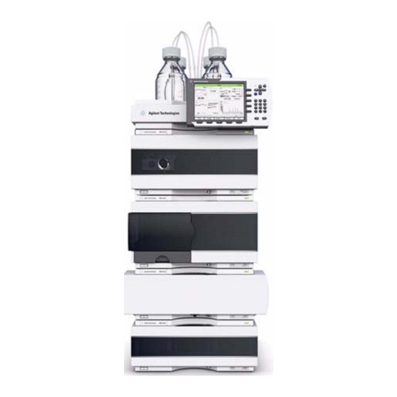
Installing the Pump Optimizing the Stack Configuration Optimizing the Stack Configuration If your module is part of a complete Agilent 1260 Infinity Liquid Chromatograph, you can ensure optimum performance by installing the following configurations. These configurations optimize the system flow path, ensuring minimum delay volume. - Page 32 Installing the Pump Optimizing the Stack Configuration Solvent cabinet Pump Instant Pilot Autosampler Thermostatted column compartment Detector Figure 4 Recommended Stack Configuration for 1260 Infinity (Front View) 1260 Infinity QuatPump VL User Manual...
- Page 33 Installing the Pump Optimizing the Stack Configuration AC power CAN bus cable to Instant Pilot Remote cable CAN bus cable LAN to control software (location depends on detector) Analog detector signal (1 or 2 outputs per detector) Figure 5 Recommended Stack Configuration for 1260 Infinity (Rear View) 1260 Infinity QuatPump VL User Manual...
-
Page 34: Installing The Pump
Installing the Pump Installing the Pump Installing the Pump Parts required Description Pump Data System and/or G4208A Instant Pilot Power cord For other cables see text below and “Cable Overview” on page 156. Preparations • Locate bench space. • Provide power connections. •... - Page 35 Installing the Pump Installing the Pump 1 Place the module on the bench in a horizontal position. 2 Ensure the power switch on the front of the module is OFF (switch stands out). Figure 6 Front of Pump 3 Connect the power cable to the power connector at the rear of the module. 1260 Infinity QuatPump VL User Manual...
- Page 36 Installing the Pump Installing the Pump 4 Connect the required interface cables to the quaternary pump, see “Connecting Modules and Control Software” on page 37. 5 Connect all capillaries, solvent tubes and waste tubing (see “Flow Connections of the Pump” on page 39).
-
Page 37: Connecting Modules And Control Software
Connecting Modules and Control Software Use of unsupplied cables WA R N I N G Using cables not supplied by Agilent Technologies can lead to damage of the electronic components or personal injury. ➔ Never use cables other than the ones supplied by Agilent Technologies to ensure proper functionality and compliance with safety or EMC regulations. -
Page 38: Connecting Control Software And/Or G4208 A Instant Pilot
Installing the Pump Connecting Modules and Control Software Connecting Control Software and/or G4208 A Instant Pilot With the introduction of the Agilent 1260 Infinity, all GPIB interfaces have been removed. N O T E The preferred communication is LAN. Usually the detector is producing the most data in the stack, followed by the pump, and it is N O T E therefore highly recommended to use either of these modules for the LAN connection. -
Page 39: Flow Connections Of The Pump
Installing the Pump Flow Connections of the Pump Flow Connections of the Pump Tools required Description 8710-0510 Wrench open 1/4 — 5/16 inch Parts required Description Other modules Parts from starter kits Preparations Pump is installed in the LC system Toxic, flammable and hazardous solvents, samples and reagents WA R N I N G The handling of solvents, samples and reagents can hold health and safety risks. - Page 40 Installing the Pump Flow Connections of the Pump 1 Remove the front cover by pressing the snap fasteners on both sides. Figure 7 Removing the Front Corver 2 Place the solvent cabinet on top of the quaternary pump. 3 Put the bottle-head assemblies into empty solvent reservoirs and place the bottle in the solvent cabinet.
- Page 41 Installing the Pump Flow Connections of the Pump 10 Prime your system before first use (see “Inital Priming” on page 42). Figure 8 Flow Connections of the Quaternary Pump 1260 Infinity QuatPump VL User Manual...
-
Page 42: Priming The System
Installing the Pump Priming the System Priming the System Inital Priming When Before a degasser or solvent tubing can be used, it is necessary to prime the system. Isopropanol is recommended as priming solvent due to its miscibility with nearly all HPLC solvents and its excellent wetting properties. - Page 43 Installing the Pump Priming the System When priming the vacuum degasser with a syringe, the solvent is drawn through the N O T E degasser tubes very quickly. The solvent at the degasser outlet will therefore not be fully degassed. Pump for approximately 10 minutes at your desired flow rate before starting an analysis.
-
Page 44: Regular Priming
Installing the Pump Priming the System Regular Priming When When the pumping system has been turned off for a certain time (for example, overnight) air will rediffuse into the solvent channel between the vacuum degasser and the pump. If solvents containing volatile components are left in the degasser without flow for a prolonged period, there will be a slight loss of the volatile components. -
Page 45: Changing Solvents
Installing the Pump Priming the System Changing Solvents When When the solvent of a channel is to be replaced by another solvent that is not compatible (solvents are immiscible or one solvent contains a buffer), it is necessary to follow the procedure below to prevent clogging of the pump by salt precipitation or residual liquid droplets in parts of the system. - Page 46 Installing the Pump Priming the System Table 4 Choice of Priming Solvents for Different Purposes Activity Solvent Comments After an installation Isopropanol Best solvent to flush air out of When switching between Isopropanol the system reverse phase and normal phase Miscible with almost all (both times) solvents...
-
Page 47: Using The Pump
Using the Pump Hints for Successful Use of the Pump Prevent Blocking of Solvent Filters Algae Growth in HPLC Systems How to Prevent and-or Reduce the Algae Problem Solvent Information This chapter provides information for optimized usage of the module. Agilent Technologies... -
Page 48: Hints For Successful Use Of The Pump
Using the Pump Hints for Successful Use of the Pump Hints for Successful Use of the Pump • Always place the solvent cabinet with the solvent bottles on top of the quaternary pump (or at a higher level). • When using salt solutions and organic solvents in the quaternary pump it is recommended to connect the salt solution to one of the bottom gradient valve ports and the organic solvent to one of the upper gradient valve ports. -
Page 49: Prevent Blocking Of Solvent Filters
Using the Pump Prevent Blocking of Solvent Filters Prevent Blocking of Solvent Filters Contaminated solvents or algae growth in the solvent bottle will reduce the lifetime of the solvent filter and will influence the performance of the module. This is especially true for aqueous solvents or phosphate buffers (pH 4 to 7). The following suggestions will prolong lifetime of the solvent filter and will maintain the performance of the module. -
Page 50: Algae Growth In Hplc Systems
Using the Pump Algae Growth in HPLC Systems Algae Growth in HPLC Systems The presence of algae in HPLC systems can cause a variety of problems that may be incorrectly diagnosed as instrument or application problems. Algae grow in aqueous media, preferably in a pH range of 4-8. Their growth is accelerated by buffers, for example phosphate or acetate. -
Page 51: Solvent Information
Using the Pump Solvent Information Solvent Information Observe the following recommendations on the use of solvents. • Follow recommendations for avoiding the growth of algae, see “Algae Growth in HPLC Systems” on page 50 • Small particles can permanently block capillaries and valves. Therefore, always filter solvents through 0.4 µm filters. - Page 52 Using the Pump Solvent Information • Solutions of organic acids (acetic acid, formic acid, and so on) in organic solvents. For example, a 1 % solution of acetic acid in methanol will attack steel. • Solutions containing strong complexing agents (for example, EDTA, ethylene diamine tetra-acetic acid).
- Page 53 Operational Hints for the Multi Channel Gradient Valve (MCGV) When to use the Seal Wash Function Choosing the Right Pump Seals Optimize the Compressibility Compensation Setting This chapter gives hints on how to optimize the performance or use additional devices. Agilent Technologies...
-
Page 54: Optimizing Performance Using The Degasser
Optimizing Performance Using the Degasser Using the Degasser The quaternary pump has a built-in degasser, which should always be included to the flow path. 1260 Infinity QuatPump VL User Manual... -
Page 55: Operational Hints For The Multi Channel Gradient Valve (Mcgv)
Optimizing Performance Operational Hints for the Multi Channel Gradient Valve (MCGV) Operational Hints for the Multi Channel Gradient Valve (MCGV) In a mixture of salt solutions and organic solvent the salt solution might be well dissolved in the organic solvent without showing precipitations. However in the mixing point of the gradient valve, at the boundary between the two solvents, micro precipitation is possible. -
Page 56: When To Use The Seal Wash Function
Optimizing Performance When to use the Seal Wash Function When to use the Seal Wash Function Highly concentrated buffer solutions will reduce the lifetime of the seals and pistons in your pump. The seal wash function allows to maintain the seal lifetime by flushing the back side of the seal with a wash solvent. -
Page 57: Choosing The Right Pump Seals
Optimizing Performance Choosing the Right Pump Seals Choosing the Right Pump Seals The standard seal for the pump can be used for most applications. However applications that use normal phase solvents (for example, hexane) are not suited for the standard seal and require a different seal when used for a longer time in the pump. -
Page 58: Optimize The Compressibility Compensation Setting
Optimizing Performance Optimize the Compressibility Compensation Setting Optimize the Compressibility Compensation Setting The compressibility compensation default setting is 100 × 10 /bar for the pump. This setting represents an average value. Under normal conditions the default setting typically reduces the pressure pulsation to values below 1 % of system pressure that are sufficient for most applications and for all gradient analyses. - Page 59 Optimizing Performance Optimize the Compressibility Compensation Setting Table 5 Solvent Compressibility Solvent (pure) Compressibility (10-6/bar) Acetone Acetonitrile Benzene Carbon tetrachloride Chloroform Cyclohexane Ethanol Ethyl acetate Heptane Hexane Isobutanol Isopropanol Methanol 1-Propanol Toluene Water 1260 Infinity QuatPump VL User Manual...
- Page 60 Optimizing Performance Optimize the Compressibility Compensation Setting 1260 Infinity QuatPump VL User Manual...
-
Page 61: Troubleshooting And Diagnostics
Overview of the Module’s Indicators and Test Functions Status Indicators Power Supply Indicator Module Status Indicator User Interfaces Agilent Lab Advisor Software This chapter gives an overview about the troubleshooting and diagnostic features and the different user interfaces. Agilent Technologies... -
Page 62: Overview Of The Module's Indicators And Test Functions
Troubleshooting and Diagnostics Overview of the Module’s Indicators and Test Functions Overview of the Module’s Indicators and Test Functions Status Indicators The module is provided with two status indicators which indicate the operational state (prerun, run, and error states) of the module. The status indicators provide a quick visual check of the operation of the module. - Page 63 Troubleshooting and Diagnostics Overview of the Module’s Indicators and Test Functions System Pressure Test The System Pressure Test is a quick test designed to determine the pressure tightness of the system (i.e. the high pressure flow path between pump and column).
-
Page 64: Status Indicators
Troubleshooting and Diagnostics Status Indicators Status Indicators Two status indicators are located on the front of the module. The lower left indicates the power supply status, the upper right indicates the module status. Figure 9 Location of Status Indicators Power Supply Indicator The power supply indicator is integrated into the main power switch. -
Page 65: Module Status Indicator
Troubleshooting and Diagnostics Status Indicators Module Status Indicator The module status indicator indicates one of six possible module conditions: • When the status indicator is OFF (and power switch light is on), the module is in a prerun condition, and is ready to begin an analysis. •... -
Page 66: User Interfaces
Troubleshooting and Diagnostics User Interfaces User Interfaces Depending on the user interface, the available tests vary. Some descriptions are only available in the service manual. Table 6 Test functions available vs. user interface Test Instant Pilot G4208A Agilent Lab Advisor System Pressure Test Yes (B.02.11) Yes (B.01.04) -
Page 67: Agilent Lab Advisor Software
Troubleshooting and Diagnostics Agilent Lab Advisor Software Agilent Lab Advisor Software The Agilent Lab Advisor software is a standalone product that can be used with or without data system. Agilent Lab Advisor software helps to manage the lab for high quality chromatographic results and can monitor in real time a single Agilent LC or all the Agilent GCs and LCs configured on the lab intranet. - Page 68 Troubleshooting and Diagnostics Agilent Lab Advisor Software 1260 Infinity QuatPump VL User Manual...
-
Page 69: Error Information
Pressure Above Upper Limit Pressure Below Lower Limit Pressure Signal Missing Missing Pressure Reading Wrong Pump Configuration MCGV Fuse AIV Fuse Valve Failed (MCGV) Motor-Drive Power Inlet-Valve Missing Temperature Out of Range Temperature Limit Exceeded Servo Restart Failed Agilent Technologies... - Page 70 Error Information Agilent Lab Advisor Software Pump Head Missing Index Limit Index Adjustment Index Missing Stroke Length Initialization Failed Wait Timeout Degasser: cannot read signal Degasser: limit not reached This chapter describes the meaning of error messages, and provides information on probable causes and suggested actions how to recover from error conditions.
-
Page 71: What Are Error Messages
Error Information What Are Error Messages What Are Error Messages Error messages are displayed in the user interface when an electronic, mechanical, or hydraulic (flow path) failure occurs which requires attention before the analysis can be continued (for example, repair, or exchange of consumables is necessary). -
Page 72: General Error Messages
Error Information General Error Messages General Error Messages General error messages are generic to all Agilent series HPLC modules and may show up on other modules as well. Timeout Error ID: 0062 The timeout threshold was exceeded. Probable cause Suggested actions Check the logbook for the occurrence and The analysis was completed successfully, source of a not-ready condition. -
Page 73: Shutdown
Error Information General Error Messages Shutdown Error ID: 0063 An external instrument has generated a shutdown signal on the remote line. The module continually monitors the remote input connectors for status signals. A LOW signal input on pin 4 of the remote connector generates the error message. -
Page 74: Remote Timeout
Error Information General Error Messages Remote Timeout Error ID: 0070 A not-ready condition is still present on the remote input. When an analysis is started, the system expects all not-ready conditions (for example, a not-ready condition during detector balance) to switch to run conditions within one minute of starting the analysis. -
Page 75: Leak
Error Information General Error Messages Leak Error ID: 0064 A leak was detected in the module. The signals from the two temperature sensors (leak sensor and board-mounted temperature-compensation sensor) are used by the leak algorithm to determine whether a leak is present. When a leak occurs, the leak sensor is cooled by the solvent. -
Page 76: Leak Sensor Short
Error Information General Error Messages Leak Sensor Short Error ID: 0082 The leak sensor in the module has failed (short circuit). The current through the leak sensor is dependent on temperature. A leak is detected when solvent cools the leak sensor, causing the leak sensor current to change within defined limits. -
Page 77: Compensation Sensor Short
Error Information General Error Messages Compensation Sensor Short Error ID: 0080 The ambient-compensation sensor (NTC) on the main board in the module has failed (short circuit). The resistance across the temperature compensation sensor (NTC) on the main board is dependent on ambient temperature. The change in resistance is used by the leak circuit to compensate for ambient temperature changes. -
Page 78: Open Cover
Error Information General Error Messages Open Cover Error ID: 0205 The top foam has been removed. The sensor on the main board detects when the top foam is in place. If the foam is removed, the fan is switched off, and the error message is generated. Probable cause Suggested actions The top foam was removed during operation. -
Page 79: Module Error Messages
Error Information Module Error Messages Module Error Messages These errors are pump specific. Solvent Zero Counter Error ID: 2055, 2524 Pump firmware version A.02.32 and higher allow to set solvent bottle fillings in the data system. If the volume level in the bottle falls below the specified value the error message appears when the feature is configured accordingly. -
Page 80: Pressure Above Upper Limit
Error Information Module Error Messages Pressure Above Upper Limit Error ID: 2014, 2500 The system pressure has exceeded the upper pressure limit. Probable cause Suggested actions Ensure the upper pressure limit is set to a value Upper pressure limit set too low. suitable for the analysis. -
Page 81: Pressure Below Lower Limit
Error Information Module Error Messages Pressure Below Lower Limit Error ID: 2015, 2501 The system pressure has fallen below the lower pressure limit. Probable cause Suggested actions Ensure the lower pressure limit is set to a value Lower pressure limit set too high. suitable for the analysis. -
Page 82: Missing Pressure Reading
Error Information Module Error Messages Missing Pressure Reading Error ID: 2054 The pressure readings read by the pump ADC (analog-digital converter) are missing. The ADC reads the pressure signal of from the damper every 1ms. If the readings are missing for longer than 10 s, the error message is generated. Probable cause Suggested actions Please contact your Agilent service... -
Page 83: Mcgv Fuse
Error Information Module Error Messages MCGV Fuse Error ID: 2043 Valve Fuse 0: Channels A and B Valve Fuse 1: Channels C and D The gradient valve in the quaternary pump has drawn excessive current causing the electronic fuse to open. Probable cause Suggested actions Restart the quaternary pump. -
Page 84: Valve Failed (Mcgv)
Error Information Module Error Messages Valve Failed (MCGV) Error ID: 2040 Valve 0 Failed: valve A Valve 1 Failed: valve B Valve 2 Failed: valve C Valve 3 Failed: valve D One of the valves of the multi-channel gradient valve has failed to switch correctly. -
Page 85: Motor-Drive Power
Error Information Module Error Messages Motor-Drive Power Error ID: 2041, 2042 The current drawn by the pump motor exceeded the maximum limit. Blockages in the flow path are usually detected by the pressure sensor in the damper, which result in the pump switching off when the upper pressure limit is exceeded. -
Page 86: Inlet-Valve Missing
Error Information Module Error Messages Inlet-Valve Missing Error ID: 2048, 2052 The active-inlet valve in the module is missing or defective. The processor checks the presence of the active-inlet valve connector every 2 s. If the connector is not detected by the processor, the error message is generated. -
Page 87: Temperature Limit Exceeded
Error Information Module Error Messages Temperature Limit Exceeded Error ID: 2517 The temperature of one of the motor-drive circuits is too high. The processor continually monitors the temperature of the drive circuits on the main board. If excessive current is being drawn for long periods, the temperature of the circuits increases. -
Page 88: Servo Restart Failed
Error Information Module Error Messages Servo Restart Failed Error ID: 2201, 2211 The pump motor in the module was unable to move into the correct position for restarting. When the module is switched on, the first step is to switch on the C phase of the variable reluctance motor. -
Page 89: Pump Head Missing
Error Information Module Error Messages Pump Head Missing Error ID: 2202, 2212 The pump-head end stop in the pump was not found. When the pump restarts, the metering drive moves forward to the mechanical end stop. Normally, the end stop is reached within 20 s, indicated by an increase in motor current. -
Page 90: Index Adjustment
Error Information Module Error Messages Index Adjustment Error ID: 2204, 2214 The encoder index position in the module is out of adjustment. During initialization, the first piston is moved to the mechanical stop. After reaching the mechanical stop, the piston reverses direction until the encoder index position is reached. -
Page 91: Stroke Length
Error Information Module Error Messages Stroke Length Error ID: 2206, 2216 The distance between the lower piston position and the upper mechanical stop is out of limits (pump). During initialization, the module monitors the drive current. If the piston reaches the upper mechanical stop position before expected, the motor current increases as the module attempts to drive the piston beyond the mechanical stop. -
Page 92: Wait Timeout
Error Information Module Error Messages Wait Timeout Error ID: 2053 When running certain tests in the diagnostics mode or other special applications, the pump must wait for the pistons to reach a specific position, or must wait for a certain pressure or flow to be reached. Each action or state must be completed within the timeout period, otherwise the error message is generated. -
Page 93: Degasser: Cannot Read Signal
Error Information Module Error Messages Degasser: cannot read signal Error ID: 2243 The pump board gets no or wrong pressure signals from the built-in degasser. Probable cause Suggested actions Please contact your Agilent service Degasser board defect, missing or not representative. - Page 94 Error Information Module Error Messages 1260 Infinity QuatPump VL User Manual...
-
Page 95: Test Functions And Calibration
System Pressure Test Running the Test Evaluating the Results Potential Causes of System Pressure Test Failure Leak Rate Test Running the Test Evaluating the Results Potential Causes of Leak Rate Test Failure This chapter describes the tests for the module. Agilent Technologies... -
Page 96: Introduction
Test Functions and Calibration Introduction Introduction Following tests are available in Lab Advisor for the Quaternary Pump G1311C: • System Pressure Test (since Lab Advisor B.02.01) • Leak Rate Test (since Lab Advisor B.01.04 SP 2) 1260 Infinity QuatPump VL User Manual... -
Page 97: System Pressure Test
Test Functions and Calibration System Pressure Test System Pressure Test Introduction The System Pressure Test is used for checking the tightness of the LC system and identifying leaks between the pump and a position in the flow path following the pump blocked by a blank nut. System requirements Minimum software revisions: •... - Page 98 Test Functions and Calibration System Pressure Test In the first phase of the test, the pump delivers flow at a rate of 200 µL/min until a pressure of 50 bar below the defined maximum pressure is reached. In the second phase, the pump delivers a small flow which is increased stepwise. If there is a leak in the system, the pressure will drop initially, as the low flow cannot compensate the leak flow.
-
Page 99: Running The Test
Test Functions and Calibration System Pressure Test Running the Test Parts required Description 01080-83202 Blank nut Damage to pressure sensitive parts C A U T I O N Even columns that are suitable for high pressures are sensitive to pressure drops that occur during this test. -
Page 100: Evaluating The Results
Test Functions and Calibration System Pressure Test Evaluating the Results The test fails, if the leak rate between pump and blank nut is higher than the limit of 3 µL/min. If the System Pressure Test fails: • Ensure that all fittings between the pump and the blank nut are tight. •... -
Page 101: Potential Causes Of System Pressure Test Failure
Test Functions and Calibration System Pressure Test Potential Causes of System Pressure Test Failure System Pressure Test failed The test will fail, if the sum of all leaks in the system (pump, autosampler or column compartment and connections) exceeds the test limit. After isolating and fixing the cause of the leak, repeat the System Pressure Test to confirm the system is pressure tight. -
Page 102: Leak Rate Test
Test Functions and Calibration Leak Rate Test Leak Rate Test Introduction The Leak Rate Test is used for verifying the internal tightness of the pump and helps identifying parts which may have caused a leak. System requirements Minimum software revisions: •... - Page 103 Test Functions and Calibration Leak Rate Test Initially, the pressure is increased to about 100 bar below the target pressure, which has been set for the test. Then piston 1 is brought to its rear position. An increasing flow is delivered by piston 1.
-
Page 104: Running The Test
Test Functions and Calibration Leak Rate Test Running the Test Parts required Description 01080-83202 Blank nut Running the test from the Agilent Lab Advisor 1 Select the Leak Rate Test from the Test Selection menu. 2 Start the test and follow the instructions. Make sure to release the pressure by slowly opening the purge valve when the test has N O T E finished. -
Page 105: Potential Causes Of Leak Rate Test Failure
Test Functions and Calibration Leak Rate Test Potential Causes of Leak Rate Test Failure Secondary Leak If a leak is found for movement of piston 2 (secondary leak), the following reasons are possible: Probable cause Suggested actions Flush system for several minutes System not flushed properly Check degasser performance Degassing efficiency is low... - Page 106 Test Functions and Calibration Leak Rate Test 1260 Infinity QuatPump VL User Manual...
-
Page 107: Maintenance
Reinstalling the Pump Head Assembly Seal Wear-in Procedure Exchanging the Multi-Channel Gradient Valve (MCGV) Exchanging the Optional Interface Board Exchanging the Active Inlet Valve (AIV) or its Cartridge Replacing the Module Firmware This chapter describes the maintenance of the module. Agilent Technologies... -
Page 108: Introduction To Maintenance
Maintenance Introduction to Maintenance Introduction to Maintenance The module is designed for easy repair. The most frequent repairs such as piston seal change and purge valve frit change can be done from the front of the module with the module in place in the system stack. These repairs are described in “Overview of Maintenance and Repair”... -
Page 109: Warnings And Cautions
Maintenance Warnings and Cautions Warnings and Cautions Toxic, flammable and hazardous solvents, samples and reagents WA R N I N G The handling of solvents, samples and reagents can hold health and safety risks. ➔ When working with these substances observe appropriate safety procedures (for example by wearing goggles, safety gloves and protective clothing) as described in the material handling and safety data sheet supplied by the vendor, and follow good laboratory practice. -
Page 110: Overview Of Maintenance And Repair
Maintenance Overview of Maintenance and Repair Overview of Maintenance and Repair The following pages describe maintenance (simple repairs) of the pump that can be carried out without opening the main cover. Table 7 Simple Repair Procedures Procedure Typical Frequency Notes “Checking and Replacing the Solvent If solvent filter is blocked Gradient performance problems, intermittent... -
Page 111: Cleaning The Module
Maintenance Cleaning the Module Cleaning the Module To keep the module case clean, use a soft cloth slightly dampened with water, or a solution of water and mild detergent. Liquid dripping into the electronic compartment of your module can cause shock WA R N I N G hazard and damage the module ➔... -
Page 112: Checking And Replacing The Solvent Filter
Maintenance Checking and Replacing the Solvent Filter Checking and Replacing the Solvent Filter A functional solvent filter is essential for a good pump performance and for protecting the LC system. When If solvent filter is blocked. Parts required Description 5041-2168 Solvent inlet filter, 20 µm pore size “Bottle Head Assembly”... -
Page 113: Exchanging The Passive Inlet Valve (Piv)
Maintenance Exchanging the Passive Inlet Valve (PIV) Exchanging the Passive Inlet Valve (PIV) When If internally leaking (backflow) Tools required Description Wrench, 14 mm Pair of tweezers Parts required Description G1312-60066 Passive inlet valve 1220/1260 Preparations Remove the front cover. Disconnect the solvent inlet tube from the inlet valve (be Using a 14 mm wrench loosen the passive inlet valve and aware that solvent may leak out of the tube due to... - Page 114 Maintenance Exchanging the Passive Inlet Valve (PIV) Next Steps: Insert the new valve into the pump head and tighten the valve using a torque wrench (12 Nm). Reconnect the solvent inlet tube to the passive inlet valve. Reinstall the front cover. 12 Nm 1260 Infinity QuatPump VL User Manual...
-
Page 115: Exchanging The Outlet Valve
Maintenance Exchanging the Outlet Valve Exchanging the Outlet Valve When If internally leaking Tools required Description 8710-0510 Wrench open 1/4 — 5/16 inch 8710-1924 Wrench open 14 mm Parts required Description G1312-60067 Outlet valve 1220/1260 Preparations • Switch off pump at the main power switch •... - Page 116 Maintenance Exchanging the Outlet Valve Reinstall the outlet valve and tighten the valve using a torque wrench (12 Nm). Reconnect the valve capillary. 12 Nm 1260 Infinity QuatPump VL User Manual...
-
Page 117: Exchanging The Purge Valve Frit
Maintenance Exchanging the Purge Valve Frit Exchanging the Purge Valve Frit When • Frit – when piston seals are exchanged or when contaminated or blocked (pressure drop of > 10 bar across the frit at a flow rate of 5 mL/min of water with purge valve opened) •... - Page 118 Maintenance Exchanging the Purge Valve Frit Place a new frit into the purge valve with the orientation N O T E of the frit as shown below (slit in frit points to the front). Before reinstallation always check the gold seal in the Reinstall the seal cap including the gold seal.
-
Page 119: Removing The Pump Head Assembly
Maintenance Removing the Pump Head Assembly Removing the Pump Head Assembly When • Exchanging the seals • Exchanging the pistons • Exchanging seals of the seal wash function Tools required Description 8710-0510 Wrench open 1/4 — 5/16 inch 8710-2392 Hexagonal key, 4.0 mm, 15 cm long, T-handle Preparations •... - Page 120 Maintenance Removing the Pump Head Assembly Using a 1/4 inch wrench remove the outlet capillary. Disconnect the capillary from the outlet valve. Remove the waste tubing and disconnect the solvent tubing from the inlet valve. Outlet valve If applicable, remove tubings from the seal wash support capillary rings.
-
Page 121: Maintenance Of A Pump Head Without Seal Wash Option
Maintenance Maintenance of a Pump Head Without Seal Wash Option Maintenance of a Pump Head Without Seal Wash Option When In case of maintenance or pump head internal leaks. Tools required Description Wrench 1/4 inch Hexagonal key, 4 mm Parts required Description 01018-23702 Insert tool... - Page 122 Maintenance Maintenance of a Pump Head Without Seal Wash Option Place the pump head on a flat surface. Loosen the lock Remove the support rings from the piston housing and lift screw (two turns) and while holding the lower half of the the housing away from the pistons.
- Page 123 Maintenance Maintenance of a Pump Head Without Seal Wash Option Using the plastic side of the insert tool, insert new seals Reassemble the pump head assembly. Note the correct into the pump head. position of the pin on the support ring. Piston seals Insert the pistons and carefully press them into the seals.
-
Page 124: Maintenance Of A Pump Head With Seal Wash Option
Maintenance Maintenance of a Pump Head with Seal Wash Option Maintenance of a Pump Head with Seal Wash Option Tools required Description 8710-2392 Hex key 4 mm15 cm long T-handle Parts required Description 01018-23702 Insert tool 0905-1175 Wash seal (PTFE) 5062-2484 Gasket, seal wash (pack of 6) 5063-6589... - Page 125 Maintenance Maintenance of a Pump Head with Seal Wash Option Remove the seal holder and the seal wash support rings Check the piston surface and remove any deposits or from the piston housing. Remove the seal holder from the layers. Cleaning can be done with alcohol or tooth paste. support ring assembly.
- Page 126 Maintenance Maintenance of a Pump Head with Seal Wash Option Using the steel side of the insert tool remove the seal wash Using the plastic side of the insert tool press the new wash gasket and the wash seal from the support ring. The seal (spring pointing upwards) into the recess of the removed seal will be damaged and cannot be re-used! support ring.
- Page 127 Maintenance Maintenance of a Pump Head with Seal Wash Option Insert the pistons and carefully press them into the seals. Tighten the lock screw. Pistons 1260 Infinity QuatPump VL User Manual...
-
Page 128: Reinstalling The Pump Head Assembly
Maintenance Reinstalling the Pump Head Assembly Reinstalling the Pump Head Assembly When When reassembling the pump Tools required Description 8710-2392 Hex key 4 mm15 cm long T-handle Parts required Description 79846-65501 Pump head grease If needed, apply a small amount of grease on the back of Slide the pump head assembly onto the pump drive and the screws. - Page 129 Maintenance Reinstalling the Pump Head Assembly Reconnect all capillaries, tubes and (if installed) the Reinstall the front cover. active inlet valve cable to its connector. 1260 Infinity QuatPump VL User Manual...
-
Page 130: Seal Wear-In Procedure
Maintenance Seal Wear-in Procedure Seal Wear-in Procedure Parts required Description 0100-1847 Adapter AIV to solvent inlet tubes 5022-2159 Restriction capillary Seal damage C A U T I O N This procedure is required for black PTFE seals (standard applications, p/n 5063-6589), but it will damage the yellow PE seals (normal phase applications, p/n 0905-1420). -
Page 131: Exchanging The Multi-Channel Gradient Valve (Mcgv)
Maintenance Exchanging the Multi-Channel Gradient Valve (MCGV) Exchanging the Multi-Channel Gradient Valve (MCGV) Tools required Description 8710-0899 Screwdriver, Pozidriv #1 Parts required Description G1311-67701 Multi channel gradient valve (MCGV) Preparations • Switch off pump at the main power switch • Remove the front cover •... - Page 132 Maintenance Exchanging the Multi-Channel Gradient Valve (MCGV) Disconnect the connecting tube, waste tube and the Press the lower sides of the cover to unclip it. Remove the solvent tubes from the MCGV. cover. Disconnect the MCGV cable, unscrew the two screws Place the new MCGV into position.
- Page 133 Maintenance Exchanging the Multi-Channel Gradient Valve (MCGV) Install the MCGV cover. Reconnect the waste funnel with the waste tube holder in the top cover. Insert waste tube in the holder in the leak pan and clip tube to the MCGV cover. Reconnect the tube from the inlet valve to the middle position of the MCGV.
-
Page 134: Exchanging The Optional Interface Board
Maintenance Exchanging the Optional Interface Board Exchanging the Optional Interface Board When Board defective Parts required Description G1351-68701 Interface board (BCD) with external contacts and BCD outputs Electronic boards are sensitive to electrostatic discharge (ESD) and should be handled C A U T I O N with care so as not to damage them. - Page 135 Maintenance Exchanging the Optional Interface Board 3 Loosen the screws. Slide out the interface board from the pump. BCD (interface) board Figure 10 Exchanging the Interface Board 4 Install the new interface board. Secure screws. 5 Reconnect the cables to the board connector. 6 Reconnect the pump to line power.
-
Page 136: Exchanging The Active Inlet Valve (Aiv) Or Its Cartridge
Maintenance Exchanging the Active Inlet Valve (AIV) or its Cartridge Exchanging the Active Inlet Valve (AIV) or its Cartridge When If internally leaking (backflow) Tools required Description Wrench, 14 mm Pair of tweezers Parts required Description G5699A Active Inlet Valve Upgrade Kit includes service and the parts listed below G1312-60025 Active inlet valve body, without cartridge (OPTIONAL) - Page 137 Maintenance Exchanging the Active Inlet Valve (AIV) or its Cartridge 5 Using a 14 mm wrench loosen the active inlet valve and remove the valve from the pump head. Figure 11 Active Inlet Valve Assembly 6 Using a pair of tweezers remove the valve cartridge from the actuator assembly.
-
Page 138: Replacing The Module Firmware
Maintenance Replacing the Module Firmware Replacing the Module Firmware When The installation of newer firmware might be necessary • if a newer version solves problems of older versions or • to keep all systems on the same (validated) revision. The installation of older firmware might be necessary •... -
Page 139: Parts For Maintenance
Purge Valve Assembly Active Inlet Valve Assembly HPLC Starter Kit G4201-68707 HPLC Starter Kit G4202-68707 HPLC System Tool Kit Solvent Cabinet Bottle Head Assembly Hydraulic Path of the Quaternary Pump This chapter provides information on parts for maintenance. Agilent Technologies... -
Page 140: Pump Head Assembly Without Seal Wash
Parts for Maintenance Pump Head Assembly Without Seal Wash Pump Head Assembly Without Seal Wash Item p/n Description G1312-60056 Pump Head 1200 SL without Seal Wash 5063-6586 Sapphire piston G1311-60002 Piston housing 5067-1560 Support Ring SL, no seal wash 5062-2484 Gasket, seal wash (pack of 6) 5042-8952 Seal holder... - Page 141 Parts for Maintenance Pump Head Assembly Without Seal Wash Figure 12 Pump head assembly without seal wash option 1260 Infinity QuatPump VL User Manual...
-
Page 142: Pump Head Assembly With Seal Wash
Parts for Maintenance Pump Head Assembly with Seal Wash Pump Head Assembly with Seal Wash Item p/n Description G1312-60045 Pump head assembly with seal wash 5063-6586 Sapphire piston G1311-60002 Piston housing 01018-60027 Support ring seal wash 0905-1175 Wash seal (PTFE) OR 4 0905-1718 Wash Seal PE... - Page 143 Parts for Maintenance Pump Head Assembly with Seal Wash Figure 13 Pump Head with Seal Wash Option 1260 Infinity QuatPump VL User Manual...
-
Page 144: Outlet Valve
Parts for Maintenance Outlet Valve Outlet Valve Description G1312-60067 Outlet valve 1220/1260 Figure 14 Outlet Valve 1260 Infinity QuatPump VL User Manual... -
Page 145: Purge Valve Assembly
Parts for Maintenance Purge Valve Assembly Purge Valve Assembly Item p/n Description G1312-60061 Purge valve 1260 01018-22707 PTFE frits (pack of 5) 5067-4728 Seal cap Figure 15 Purge Valve Assembly 1260 Infinity QuatPump VL User Manual... -
Page 146: Active Inlet Valve Assembly
Parts for Maintenance Active Inlet Valve Assembly Active Inlet Valve Assembly Item p/n Description G5699A Active Inlet Valve Upgrade Kit includes service and the parts listed below G1312-60025 Active inlet valve body, without cartridge 5062-8562 Active Inlet Valve Cartridge (400 bar) G1311-67304 Connecting tube, MCGV to AIV Figure 16... -
Page 147: Hplc Starter Kit G4201-68707
Parts for Maintenance HPLC Starter Kit G4201-68707 HPLC Starter Kit G4201-68707 HPLC Starter Kit incl. 0.17 mm i.d. cap (p/n G4201-68707) Description 9301-1420 (3x) Solvent bottle, transparent 9301-1450 Solvent bottle, amber 01018-22707 PTFE frits (pack of 5) 5182-0716 Screw Cap Vial, 2 mL, amber glass, write-on spot, 100/pk 5182-0717 Blue screw caps 100/pk 5063-6507 (2x) Chip, Column I.D. -
Page 148: Hplc Starter Kit G4202-68707
Parts for Maintenance HPLC Starter Kit G4202-68707 HPLC Starter Kit G4202-68707 HPLC Starter Kit incl. 0.12 mm i.d. cap (p/n G4202-68707) Description 9301-1420 (3x) Solvent bottle, transparent 9301-1450 Solvent bottle, amber 01018-22707 PTFE frits (pack of 5) 5182-0716 Screw Cap Vial, 2 mL, amber glass, write-on spot, 100/pk 5182-0717 Blue screw caps 100/pk 5063-6507 (2x) Chip, Column I.D. -
Page 149: Hplc System Tool Kit
Parts for Maintenance HPLC System Tool Kit HPLC System Tool Kit HPLC System Tool Kit (p/n G4203-68708) Description 0100-1681 Adapter syringe/seal wash tube 0100-1710 Mounting Tool for Tubing Connections 01018-23702 Insert tool 5023-0240 Hex driver, ¼", slitted 8710-0060 Hex-key wrench, 9/64 inch 8710-0510 (2x) Wrench open 1/4 —... -
Page 150: Solvent Cabinet
Parts for Maintenance Solvent Cabinet Solvent Cabinet Item p/n Description 5067-4770 Solvent Cabinet Kit 5043-0207 Name plate 1260 5065-9954 Front panel, solvent cabinet 5042-8907 Leak pan, solvent cabinet 9301-1420 Solvent bottle, transparent 9301-1450 Solvent bottle, amber G1311-60003 Bottle-head assembly Figure 17 Solvent Cabinet Parts 1260 Infinity QuatPump VL User Manual... -
Page 151: Bottle Head Assembly
Parts for Maintenance Bottle Head Assembly Bottle Head Assembly Item p/n Description G1311-60003 Bottle-head assembly 5063-6598 Ferrules with lock ring (10/Pk) 5063-6599 Tube screw (10/Pk) Wire marker 5062-2483 Solvent tubing, 5 m 5062-8517 Inlet filter adapter (4/Pk) 5041-2168 Solvent inlet filter, 20 µm pore size Figure 18 Bottle-Head Assembly Parts 1260 Infinity QuatPump VL User Manual... -
Page 152: Hydraulic Path Of The Quaternary Pump
Parts for Maintenance Hydraulic Path of the Quaternary Pump Hydraulic Path of the Quaternary Pump Item p/n Description G1312-67305 Outlet capillary, pump to injector G1329-87300 Outlet capillary, pump to thermostattable autosampler G1311-60003 Bottle-head assembly G1322-67300 Kit of 4 solvent tubes for connection degasser to MCGV including labels G1311-81600 Capillary, damper to inlet pump chamber 2 G1311-81601... - Page 153 Parts for Maintenance Hydraulic Path of the Quaternary Pump Figure 19 Hydraulic Flow Path of the Quaternary Pump 1260 Infinity QuatPump VL User Manual...
- Page 154 Parts for Maintenance Hydraulic Path of the Quaternary Pump 1260 Infinity QuatPump VL User Manual...
-
Page 155: Identifying Cables
Identifying Cables Cable Overview Analog Cables Remote Cables BCD Cables CAN Cable External Contact Cable Agilent Module to PC Agilent 1200 Module to Printer This chapter provides information on cables used with the Agilent 1200 Infinity Series modules. Agilent Technologies... -
Page 156: Cable Overview
Identifying Cables Cable Overview Cable Overview Never use cables other than the ones supplied by Agilent Technologies to ensure proper N O T E functionality and compliance with safety or EMC regulations. Analog cables Description 35900-60750 Agilent module to 3394/6 integrators... - Page 157 Identifying Cables Cable Overview CAN cables Description 5181-1516 CAN cable, Agilent module to module, 0.5 m 5181-1519 CAN cable, Agilent module to module, 1 m LAN cables Description 5023-0203 Cross-over network cable, shielded, 3 m (for point to point connection) 5023-0202 Twisted pair network cable, shielded, 7 m (for point to point connection) External Contact Cable...
-
Page 158: Analog Cables
Identifying Cables Analog Cables Analog Cables One end of these cables provides a BNC connector to be connected to Agilent modules. The other end depends on the instrument to which connection is being made. Agilent Module to 3394/6 Integrators p/n 35900-60750 Pin 3394/6 Pin Agilent Signal Name... - Page 159 Identifying Cables Analog Cables Agilent Module to General Purpose p/n 01046-60105 Pin Agilent Signal Name module Not connected Black Analog - Analog + 1260 Infinity QuatPump VL User Manual...
-
Page 160: Remote Cables
Identifying Cables Remote Cables Remote Cables One end of these cables provides a Agilent Technologies APG (Analytical Products Group) remote connector to be connected to Agilent modules. The other end depends on the instrument to be connected to. Agilent Module to 3396A Integrators... - Page 161 Identifying Cables Remote Cables Agilent Module to 3396 Series III / 3395B Integrators p/n 03396-61010 Pin 33XX Pin Agilent Signal Name Active module (TTL) 1 - White Digital ground 2 - Brown Prepare run 3 - Gray Start 4 - Blue Shut down 5 - Pink Not connected...
- Page 162 Identifying Cables Remote Cables Agilent Module to General Purpose p/n 01046-60201 Wire Color Pin Agilent Signal Name Active module (TTL) White Digital ground Brown Prepare run Gray Start Blue Shut down Pink Not connected Yellow Power on High Ready High Green Stop Black...
-
Page 163: Bcd Cables
Identifying Cables BCD Cables BCD Cables One end of these cables provides a 15-pin BCD connector to be connected to the Agilent modules. The other end depends on the instrument to be connected to Agilent Module to General Purpose p/n G1351-81600 Wire Color Pin Agilent Signal Name... - Page 164 Identifying Cables BCD Cables Agilent Module to 3396 Integrators p/n 03396-60560 Pin 3396 Pin Agilent Signal Name BCD Digit module BCD 5 BCD 7 BCD 6 BCD 4 BCD0 BCD 3 BCD 2 BCD 1 Digital ground + 5 V 1260 Infinity QuatPump VL User Manual...
-
Page 165: Can Cable
Identifying Cables CAN Cable CAN Cable Both ends of this cable provide a modular plug to be connected to Agilent modules CAN or LAN connectors. CAN Cables Description 5181-1516 CAN cable, Agilent module to module, 0.5 m 5181-1519 CAN cable, Agilent module to module, 1 m LAN Cables Description 5023-0203... -
Page 166: External Contact Cable
Identifying Cables External Contact Cable External Contact Cable One end of this cable provides a 15-pin plug to be connected to Agilent modules interface board. The other end is for general purpose. Agilent Module Interface Board to general purposes p/n G1103-61611 Color Pin Agilent Signal Name... -
Page 167: Agilent Module To Pc
Identifying Cables Agilent Module to PC Agilent Module to PC Description G1530-60600 RS-232 cable, 2 m RS232-61600 RS-232 cable, 2.5 m Instrument to PC, 9-to-9 pin (female). This cable has special pin-out, and is not compatible with connecting printers and plotters. It's also called "Null Modem Cable"... -
Page 168: Agilent 1200 Module To Printer
Identifying Cables Agilent 1200 Module to Printer Agilent 1200 Module to Printer Description 5181-1529 Cable Printer Serial & Parallel, is a SUB-D 9 pin female vs. Centronics connector on the other end (NOT FOR FW UPDATE). For use with G1323 Control Module. 1260 Infinity QuatPump VL User Manual... -
Page 169: Hardware Information
Optional Interface Boards Electrical Connections Rear View of the Module Interfaces Overview Interfaces Setting the 8-bit Configuration Switch (without On-board) LAN Communication Settings for RS-232C Special Settings This chapter describes the pump in more detail on hardware and electronics. Agilent Technologies... -
Page 170: Firmware Description
Hardware Information Firmware Description Firmware Description The firmware of the instrument consists of two independent sections: • a non-instrument specific section, called resident system • an instrument specific section, called main system Resident System This resident section of the firmware is identical for all Agilent 1100/1200/1220/1260/1290 series modules. - Page 171 Hardware Information Firmware Description Firmware Updates Firmware updates can be done using your user interface: • PC and Firmware Update Tool with local files on the hard disk • Instant Pilot (G4208A) with files from a USB Flash Disk • Agilent Lab Advisor software B.01.03 and above The file naming conventions are: PPPP_RVVV_XXX.dlb, where PPPP is the product number, for example, 1315AB for the G1315A/B DAD,...
- Page 172 Hardware Information Firmware Description Some modules are limited in downgrading due to their main board version or their initial N O T E firmware revision. For example, a G1315C DAD SL cannot be downgraded below firmware revision B.01.02 or to a A.xx.xx. Some modules can be re-branded (e.g.
-
Page 173: Optional Interface Boards
Hardware Information Optional Interface Boards Optional Interface Boards BCD / External Contact Board The Agilent 1200 Infinity Series modules have one optional board slot that allows to add an interface board to the modules. Some modules do not have this interface slot. Refer to “Interfaces”... - Page 174 Hardware Information Optional Interface Boards There are general purpose cables available to connect the BCD output, see “BCD Cables” on page 163 and the external outputs, see “External Contact Cable” on page 166 to external devices. Table 8 Detailed connector layout (1200) Signal name BCD digit BCD 5...
- Page 175 Hardware Information Optional Interface Boards LAN Communication Interface Board The Agilent modules have one optional board slot that allows to add an interface board to the modules. Some modules do not have this interface slot. Refer to “Interfaces” on page 179 for details. Description G1369B or Interface board (LAN)
- Page 176 The following cards can be used with the Agilent 1260 Infinity modules. Table 9 LAN Boards Type Vendor Supported networks Interface board (LAN) (p/n Agilent Technologies Fast Ethernet, Ethernet/802.3, G1369B or G1369-60002) or RJ-45 (10/100Base-TX) Interface board (LAN) (p/n recommended for re-ordering G1369C or G1369-60012)
-
Page 177: Electrical Connections
There are no externally accessible fuses, because automatic electronic fuses are implemented in the power supply. Never use cables other than the ones supplied by Agilent Technologies to ensure proper N O T E functionality and compliance with safety or EMC regulations. -
Page 178: Rear View Of The Module
Hardware Information Electrical Connections Rear View of the Module Figure 21 Rear view of the pump 1260 Infinity QuatPump VL User Manual... -
Page 179: Interfaces
Hardware Information Interfaces Interfaces The Agilent 1200 Infinity Series modules provide the following interfaces: Table 10 Agilent 1200 Infinity Series Interfaces Module LAN/BCD RS-232 Analog Special (optional) (on-board) Remote Pumps G1310B Iso Pump G1311B Quat Pump G1311C Quat Pump VL G1312B Bin Pump G1312C Bin Pump VL 1376A Cap Pump... - Page 180 Hardware Information Interfaces Table 10 Agilent 1200 Infinity Series Interfaces Module LAN/BCD RS-232 Analog Special (optional) (on-board) Remote Detectors G1314B VWD VL G1314C VWD VL+ G1314E/F VWD G4212A/B DAD G1315C DAD VL+ G1365C MWD G1315D DAD VL G1365D MWD VL G1321B FLD G1362A RID G4280A ELSD...
-
Page 181: Overview Interfaces
Hardware Information Interfaces The detector (DAD/MWD/FLD/VWD/RID) is the preferred access point for control via N O T E LAN. The inter-module communication is done via CAN. • CAN connectors as interface to other modules • LAN connector as interface to the control software •... - Page 182 Hardware Information Interfaces There is no configuration possible on main boards with on-board LAN. These are N O T E pre-configured for • 19200 baud, • 8 data bit with no parity and • one start bit and one stop bit are always used (not selectable). The RS-232C is designed as DCE (data communication equipment) with a 9-pin male SUB-D type connector.
- Page 183 APG Remote The APG Remote connector may be used in combination with other analytical instruments from Agilent Technologies if you want to use features as common shut down, prepare, and so on. Remote control allows easy connection between single instruments or systems to ensure coordinated analysis with simple coupling requirements.
- Page 184 Hardware Information Interfaces • input load is 2.2 kOhm against + 5.0 V, and • output are open collector type, inputs/outputs (wired- or technique). All common TTL circuits operate with a 5 V power supply. A TTL signal is defined as "low" N O T E or L when between 0 V and 0.8 V and "high"...
-
Page 185: Setting The 8-Bit Configuration Switch (Without On-Board) Lan
Hardware Information Setting the 8-bit Configuration Switch (without On-board) LAN Setting the 8-bit Configuration Switch (without On-board) LAN The 8-bit configuration switch is located at the rear of the module. This module does not have its own on-board LAN interface. It can be controlled through the LAN interface of another module, and a CAN connection to that module. -
Page 186: Communication Settings For Rs-232C
Hardware Information Setting the 8-bit Configuration Switch (without On-board) LAN The following tables represent the configuration switch settings for the modules without N O T E on-board LAN only. Table 13 8-bit Configuration Switch (without on-board LAN) Mode Select RS-232C Baudrate Data Parity... - Page 187 Hardware Information Setting the 8-bit Configuration Switch (without On-board) LAN Table 15 Baudrate Settings (without on-board LAN) Switches Baud Rate Switches Baud Rate 9600 9600 1200 14400 2400 19200 4800 38400 Table 16 Data Bit Settings (without on-board LAN) Switch 6 Data Word Size 7 Bit Communication 8 Bit Communication...
-
Page 188: Special Settings
Hardware Information Setting the 8-bit Configuration Switch (without On-board) LAN Special Settings The special settings are required for specific actions (normally in a service case). Boot-Resident Firmware update procedures may require this mode in case of firmware loading errors (main firmware part). If you use the following switch settings and power the instrument up again, the instrument firmware stays in the resident mode. - Page 189 Hardware Information Setting the 8-bit Configuration Switch (without On-board) LAN Forced Cold Start A forced cold start can be used to bring the module into a defined mode with default parameter settings. Loss of data C A U T I O N Forced cold start erases all methods and data stored in the non-volatile memory.
- Page 190 Hardware Information Setting the 8-bit Configuration Switch (without On-board) LAN 1260 Infinity QuatPump VL User Manual...
-
Page 191: Appendix
1260 Infinity QuatPump VL User Manual Appendix General Safety Information The Waste Electrical and Electronic Equipment Directive Batteries Information Radio Interference Sound Emission Agilent Technologies on Internet This chapter provides addition information on safety, legal and web. Agilent Technologies... -
Page 192: General Safety Information
Appendix General Safety Information General Safety Information Safety Symbols Table 20 Safety Symbols Symbol Description The apparatus is marked with this symbol when the user should refer to the instruction manual in order to protect risk of harm to the operator and to protect the apparatus against damage. - Page 193 Appendix General Safety Information General Safety Information The following general safety precautions must be observed during all phases of operation, service, and repair of this instrument. Failure to comply with these precautions or with specific warnings elsewhere in this manual violates safety standards of design, manufacture, and intended use of the instrument.
- Page 194 Appendix General Safety Information Operation Before applying power, comply with the installation section. Additionally the following must be observed. Do not remove instrument covers when operating. Before the instrument is switched on, all protective earth terminals, extension cords, auto-transformers, and devices connected to it must be connected to a protective earth via a ground socket.
-
Page 195: The Waste Electrical And Electronic Equipment Directive
Appendix The Waste Electrical and Electronic Equipment Directive The Waste Electrical and Electronic Equipment Directive Abstract The Waste Electrical and Electronic Equipment (WEEE) Directive (2002/96/EC), adopted by EU Commission on 13 February 2003, is introducing producer responsibility on all electric and electronic appliances starting with 13 August 2005. -
Page 196: Batteries Information
Appendix Batteries Information Batteries Information Lithium batteries may not be disposed-off into the domestic waste. Transportation of WA R N I N G discharged Lithium batteries through carriers regulated by IATA/ICAO, ADR, RID, IMDG is not allowed. Danger of explosion if battery is incorrectly replaced. ➔... -
Page 197: Radio Interference
Appendix Radio Interference Radio Interference Cables supplied by Agilent Technologies are screened to provide optimized protection against radio interference. All cables are in compliance with safety or EMC regulations. Test and Measurement If test and measurement equipment is operated with unscreened cables, or... -
Page 198: Sound Emission
Appendix Sound Emission Sound Emission Manufacturer’s Declaration This statement is provided to comply with the requirements of the German Sound Emission Directive of 18 January 1991. This product has a sound pressure emission (at the operator position) < 70 dB. •... -
Page 199: Agilent Technologies On Internet
Appendix Agilent Technologies on Internet Agilent Technologies on Internet For the latest information on products and services visit our worldwide web site on the Internet at: http://www.agilent.com Select Products/Chemical Analysis It will provide also the latest firmware of the modules for download. - Page 200 Index Index cable RS-232C bench space compensation sensor open 8-bit configuration switch blockage compensation sensor short without On-Board LAN board composition precision HP JetDirect card composition range boards compressibility compensation 15, 24, active inlet valve cartridge LAN card active inlet valve 136, bottle head assembly condensation...
- Page 201 Index error messages, degasser limit not multi channel gradient valve hydraulic path reached (MCGV) hydraulic system optional interface board error messages outlet valve 115, lost CAN partner passive inlet valve pump error index adjustment pistons remote timeout index limit pump seals error messages index missing purge valve frit...
- Page 202 Index overview outlet valve remote replacing firmware 138, pump head without seal wash cable pump head with seal wash MCGV fuse removing solvent cabinet pump head assembly MCGV system tool kit repairs message passive inlet valve replacing firmware 138, ignition without cover pH range remote timeout RS-232C...
- Page 203 Index replacing variable reluctance motor solvents, change variable stroke volume sound emission voltage range special interfaces special settings boot-resident wait timeout forced cold start waste specification electrical and electronic physical equipment status indicator wear-in stroke length procedure stroke volume WEEE directive system pressure test, evaluating weight results...
- Page 204 • using the pump, • optimizing performance, • troubleshooting and diagnostics, • maintenance, • parts and materials for maintenance, • identifiying cables, • hardware information, • appendix. Agilent Technologies 2010-2011, 2012 Printed in Germany 01/2012 *G1311-90014* *G1311-90014* G1311-90014 Agilent Technologies...