Agilent Technologies InfinityLab LC Series User Manual
Hide thumbs
Also See for InfinityLab LC Series:
- User manual (369 pages) ,
- Quick manual (82 pages) ,
- Installation manual (12 pages)

Related Manuals for Agilent Technologies InfinityLab LC Series


Summary of Contents for Agilent Technologies InfinityLab LC Series
- Page 1 Refractive Index Detector Agilent InfinityLab LC Series User Manual Agilent InfinityLab LC Series RID User Manual...
- Page 2 12.211 (Technical Data) and 12.212 (Computer Software) and, for the Depart- ment of Defense, DFARS 252.227-7015 (Technical Data - Commercial Items) and DFARS 227.7202-3 (Rights in Commer- cial Computer Software or Computer Software Documentation). Agilent InfinityLab LC Series RID User Manual...
- Page 3 This chapter gives an overview about the troubleshooting and diagnostic features and the different user interfaces. Error Information This chapter describes the meaning of error messages, and provides information on probable causes and suggested actions how to recover from error conditions. Agilent InfinityLab LC Series RID User Manual...
- Page 4 This chapter describes the module in more detail on hardware and electronics. LAN Configuration This chapter provides information on connecting the module to the Agilent ChemStation PC. Appendix This chapter provides safetey and other general information. Agilent InfinityLab LC Series RID User Manual...
-
Page 5: Table Of Contents
Set up the Detector with Agilent Open Lab ChemStation The Detector User Interface Detector Control Settings Method Parameter Settings Agilent Local Control Modules Preparing the Module Leak and Waste Handling Setting up an Analysis Solvent Information Agilent InfinityLab LC Series RID User Manual... - Page 6 Maintenance and Repair Introduction to Maintenance Warnings and Cautions Overview of Maintenance Cleaning the Module Remove and Install Doors Flow Cell Flushing Correct Leaks Replace Leak Handling System Parts Replace the Module Firmware Agilent InfinityLab LC Series RID User Manual...
- Page 7 Instrument Layout Early Maintenance Feedback LAN Configuration What You Have to Do First TCP/IP parameter configuration Configuration Switches Initialization Mode Selection Dynamic Host Configuration Protocol (DHCP) Manual Configuration PC and Agilent ChemStation Setup Agilent InfinityLab LC Series RID User Manual...
- Page 8 In This Guide... Appendix General Safety Information Waste Electrical and Electronic Equipment (WEEE) Directive Radio Interference Sound Emission Solvent Information Agilent Technologies on Internet Agilent InfinityLab LC Series RID User Manual...
-
Page 9: Introduction To The Refractive Index Detector
G7162B Refractive Index Detector Product Description Features How the Detector Operates Detection Principle Flow Path Leak and Waste Handling Leak Sensor Waste Guidance Waste Concept This chapter gives an introduction to the Refractive Index Detector. Agilent InfinityLab LC Series RID User Manual... -
Page 10: Introduction To The Refractive Index Detector
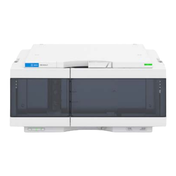
• built-in refractive index calibration, • front access to valves and capillaries for easy maintenance. For specifications, see “Performance Specifications” on page 38. Figure 1 The Agilent 1200 Infinity Series Refractive Index Detector Agilent InfinityLab LC Series RID User Manual... - Page 11 It comprises the following features: • inlet port to sample cell 10 µL, • inlet port to outlet port 265 µL, • maximum data rate up to 148 Hz, • LED illumination. Agilent InfinityLab LC Series RID User Manual...
-
Page 12: G7162A Refractive Index Detector
(GPC) or size exclusion chromatography (SEC). Status indicator Interface port area Service door Power switch Leak drain Figure 2 Overview of the detector Agilent InfinityLab LC Series RID User Manual... -
Page 13: Features
Automatic offset adjustment for easy detection and quantification of negative peaks, and a time-programmable polarity switch for simple inversion of peaks for ease of integration • Excellent linear response for compounds with little or no UV chromaphore in a wide concentration range Agilent InfinityLab LC Series RID User Manual... -
Page 14: G7162B Refractive Index Detector
A high-performance detector of choice for accurate, reproducible, routine analysis of polymers and other compounds that aren’t detectable by UV. Status indicator Interface port area Service door Power switch Leak drain Figure 3 Overview of the detector Agilent InfinityLab LC Series RID User Manual... -
Page 15: Features
Early maintenance feedback (EMF) – indicates that preventative maintenance is due. • Extensive diagnostics – includes error detection and display with Instant Pilot controller and Lab Advisor software. • RoHS compliant – aligned with European Union directives regarding specific hazardous materials. Agilent InfinityLab LC Series RID User Manual... -
Page 16: How The Detector Operates
= Refractive index of medium 1 • α = angle of incident light in medium 1 • α = angle of refraction in medium 2 Medium 1 Medium 2 Figure 4 Light Refraction Agilent InfinityLab LC Series RID User Manual... - Page 17 The density of a medium will be affected by the following factors: • Composition (if not a pure substance) • Temperature • Pressure Agilent InfinityLab LC Series RID User Manual...
-
Page 18: Detection Principle
The light receiver has two diodes each of which produces an electrical current proportional to the amount of light that falls upon it (see Figure 5 on page 18). Figure 5 Light path Agilent InfinityLab LC Series RID User Manual... - Page 19 Lamp Condenser lens Incident light Diodes Zero glass Deflected light Collimator lens Sample cell Reference cell Mirror Figure 6 Optical Path Agilent InfinityLab LC Series RID User Manual...
-
Page 20: Flow Path
If the Automatic zero before analysis mode is enabled the detector output will be set to zero immediately before the analysis begins. The different flow paths depend on the status of the Purge Valve and Recycle Valve. Agilent InfinityLab LC Series RID User Manual... - Page 21 Normal Flow Mode Purge Valve = OFF, Recycle Valve = OFF Purge valve Zero glass Diodes Recycle Reference Interconnection Mirror cell valve Collimator Sample Lamp Slit lens cell Condenser Heat lens exchanger Heater Safety cap Agilent InfinityLab LC Series RID User Manual...
- Page 22 Purge Valve = ON, Recycle Valve = OFF Purge valve Zero glass Diodes Recycle Interconnection Reference valve Mirror cell Sample Collimator Slit Lamp cell lens Condenser Heat lens exchanger Heater Safety cap Agilent InfinityLab LC Series RID User Manual...
- Page 23 Purge Valve = OFF, Recycle Valve = ON Purge valve Zero glass Diodes Recycle Interconnection Reference valve Mirror cell Sample Collimator Slit Lamp cell lens Condenser Heat lens exchanger Heater Safety cap Agilent InfinityLab LC Series RID User Manual...
- Page 24 1.0 mm, except for (2), which has an ID of 0.2 mm. All other tubings (to and from the purge and the reference valve) are made of PTFE (available as Tubing kit (G1362-68709)). Agilent InfinityLab LC Series RID User Manual...
- Page 25 Grey lines = flowing path Black lines = immobilized mobile phase The T-connection in the metal union block results in both sides of the flow cell (sample and reference) always being exposed to the same pressure Agilent InfinityLab LC Series RID User Manual...
- Page 26 Grey lines = flowing path Black lines = immobilized mobile phase The T-connection in the metal union block results in both sides of the flow cell (sample and reference) always being exposed to the same pressure Agilent InfinityLab LC Series RID User Manual...
-
Page 27: Leak And Waste Handling
Introduction to the Refractive Index Detector Leak and Waste Handling Leak and Waste Handling The Agilent InfinityLab LC Series has been designed for safe leak and waste handling. It is important that all security concepts are understood and instructions are carefully followed. - Page 28 Introduction to the Refractive Index Detector Leak and Waste Handling Figure 10 Infinity II Leak Waste Concept (Flex Bench installation) Agilent InfinityLab LC Series RID User Manual...
- Page 29 Introduction to the Refractive Index Detector Leak and Waste Handling Figure 11 Infinity II Single Stack Leak Waste Concept (bench installation) Agilent InfinityLab LC Series RID User Manual...
- Page 30 Figure 12 Infinity II Two Stack Leak Waste Concept (bench installation) The waste tube connected to the leak pan outlet on each of the bottom instruments guides the solvent to a suitable waste container. Agilent InfinityLab LC Series RID User Manual...
-
Page 31: Leak Sensor
Do not use DMF as mobile phase. Check the leak sensor regularly for corrosion. Waste Guidance The waste drainage must go straight into the waste containers. The waste flow NOTE must not be restricted at bends or joints. Agilent InfinityLab LC Series RID User Manual... -
Page 32: Waste Concept
To optimize detector performance the waste container and solvent bottle should NOTE be positioned above the level of the refractive index detector and solvent pump (e.g. in the solvent compartment). This will maintain a slight pressure in the sample cell. Agilent InfinityLab LC Series RID User Manual... -
Page 33: Site Requirements And Specifications
Site Requirements and Specifications Site Requirements Physical Specifications Performance Specifications This chapter provides information on environmental requirements, physical and performance specifications. Agilent InfinityLab LC Series RID User Manual... -
Page 34: Site Requirements
Make sure the power connector of the instrument can be easily reached and unplugged. Provide sufficient space behind the power socket of the instrument to unplug the cable. Agilent InfinityLab LC Series RID User Manual... - Page 35 Never use a power cord other than the one that Agilent shipped with this instrument. Never use the power cords that Agilent Technologies supplies with this instrument for any other equipment. Never use cables other than the ones supplied by Agilent Technologies ...
- Page 36 This module is designed to operate in a typical electromagnetic environment, i.e. NOTE where RF transmitters such as mobile telephones may not be used in close proximity. Agilent InfinityLab LC Series RID User Manual...
-
Page 37: Physical Specifications
Up to 3000 m (9842 ft) Safety standards: IEC, EN, Installation category II, Pollution degree 2 For indoor use only. CSA, UL ISM Classification ISM Group 1 Class B According to CISPR 11 Agilent InfinityLab LC Series RID User Manual... -
Page 38: Performance Specifications
Agilent Instant Pilot (G4208A) Analog outputs Recorder/integrator: 100 mV or 1 V, output range selectable, one out- Communication LAN, Controller Area Network (CAN), Extended Remote Interface (ERI): ready, start, stop and shut-down signals Agilent InfinityLab LC Series RID User Manual... - Page 39 Liquid Chromatography. Reference conditions; optics temperature 35 °C, response time 4 s, flow 1.0 mL/min LC-grade Water, restriction capillary, column compartment temperature 35 °C, Agilent on-line degasser (e.g. G4225A), pump and thermostatted column compartment. Instrument equilibrated for 2 hours. Agilent InfinityLab LC Series RID User Manual...
- Page 40 (ERI): ready, start, stop and shut-down signals Safety and maintenance Extensive diagnostics, error detection and display, leak detection, safe leak handling, leak output signal for shutdown of pumping sys- tem. Low voltages in major maintenance areas. Agilent InfinityLab LC Series RID User Manual...
- Page 41 Liquid Chromatography. Reference conditions; optics temperature 35 °C, response time 4 s, flow 1.0 mL/min LC-grade Water, restriction capillary, column compartment temperature 35 °C, Agilent on-line degasser (e.g. G4225A), pump and thermostatted column compartment. Instrument equilibrated for 2 hours. Agilent InfinityLab LC Series RID User Manual...
-
Page 42: Using The Module
Set up the Detector with Agilent Open Lab ChemStation The Detector User Interface Detector Control Settings Method Parameter Settings Agilent Local Control Modules This chapter explains the essential operational parameters of the module. Agilent InfinityLab LC Series RID User Manual... -
Page 43: Magnets
Using the Module Magnets Magnets Magnets in doors of pumps, autosamplers, detectors, and fraction collectors. Agilent InfinityLab LC Series RID User Manual... -
Page 44: Turn On/Off
Using the Module Turn on/off Turn on/off This procedure exemplarily shows an arbitrary LC stack configuration. Power switch: On Agilent InfinityLab LC Series RID User Manual... - Page 45 Using the Module Turn on/off Turn instrument On/Off with the control software. Power switch: Off Agilent InfinityLab LC Series RID User Manual...
-
Page 46: Status Indicators
5. Resident mode (blinking) - for example during update of main firmware. 6. Bootloader mode (fast blinking). Try to re-boot the module or try a cold-start. Then try a firmware update. Agilent InfinityLab LC Series RID User Manual... -
Page 47: Instrument Configuration
1 Set the switches of the Configuration switch at the rear of the module: a All switches DOWN: module uses the default IP address 192.168.254.11. b Switch 4 UP and others DOWN: module uses DHCP. c Switch 5 UP and others DOWN: modules uses STORED address Agilent InfinityLab LC Series RID User Manual... - Page 48 Using the Module Instrument Configuration 2 Enter the setup information (MAC / IP address and/or Instrument Name). a Agilent OpenLAB ChemStation (Configure Instrument): b Lab Advisor (Instrument Overview - Add Instrument): Agilent InfinityLab LC Series RID User Manual...
-
Page 49: Set Up The Detector With Agilent Open Lab Chemstation
Figure 13 ChemStation Method and Run Control (just detector is shown) After successful load of the OpenLab ChemStation, you should see the module as an active item in the graphical user interface (GUI). Agilent InfinityLab LC Series RID User Manual... -
Page 50: The Detector User Interface
Make device ready or turn off EMF status Detector status Balance Heater status (on/off) Heater temperature The Purge Valve status (closed/open) and the Recycle Valve status (off/on) is shown when the cursor moves across the flow cell icon. Agilent InfinityLab LC Series RID User Manual... - Page 51 Identify Module (Status LED will blink) • Perform a Balance • Switch the Heater on/off (same as click on button Make Device Ready/Turn device off (standby)) • Open/close Purge Valve • Recycle Valve on/off Agilent InfinityLab LC Series RID User Manual...
- Page 52 Using the Module The Detector User Interface If the Purge Valve or Recycle Valve has been turned on, the on-time is displayed below the flow cell icon. Agilent InfinityLab LC Series RID User Manual...
-
Page 53: Detector Control Settings
55). • At Power On: When activated, the optical unit heater is turned on automatically when the RID is switched on. For shortest equilibration times, Agilent recommends to leave this function always on. Agilent InfinityLab LC Series RID User Manual... - Page 54 It requires that the At Power On function is turned off. Select Turn Heater on at: to activate the date and time fields, and enter the date and time in the appropriate fields in the specified format. Agilent InfinityLab LC Series RID User Manual...
-
Page 55: Method Parameter Settings
(does not show the Instrument Curves tab). Figure 15 Method parameter settings For additional help and support: Highlight the desired cell and press F1. A help NOTE screen will open with additional information and documentation about the topic. Agilent InfinityLab LC Series RID User Manual... - Page 56 Zero Offset: 1 – 99 % in steps of 1 % (5 % equal to 50 mV). • Attenuation: 488 – 1000000 nRIU at discrete values for either 100 mV or 1 V full scale. Agilent InfinityLab LC Series RID User Manual...
- Page 57 Time Limits: 0.00 to 99999.00 min in steps of 0.01 min. Via the buttons in the bottom area time table lines can be added, removed, cut copied, pasted or completely cleared. Based on the chosen function, a certain parameter can be selected. Agilent InfinityLab LC Series RID User Manual...
- Page 58 1 and diode 2. • Board Temperature The temperature around the Leak Sensor (at the power switch electronics) can be used for looking at ambient temperature changes. Agilent InfinityLab LC Series RID User Manual...
-
Page 59: Agilent Local Control Modules
• a clear overview of the system status • control functionalities • access to method parameters and sequences • a logbook showing events from the modules • diagnose tests Agilent InfinityLab LC Series RID User Manual... - Page 60 Factory installed software – flat dialog structure, user configurable interface, enhanced sequence engine, for example with wait for baseline stabilization, diagnosis with passed/failed. • GLP – System logbook and module logbooks record errors, unusual events, and maintenance activities for GLP traceability. Agilent InfinityLab LC Series RID User Manual...
-
Page 61: Preparing The Module
Preparing the Detector Preparing the HPLC System Running the Sample and Verifying the Results Solvent Information This chapter provides information on how to set up the module for an analysis and explains the basic settings. Agilent InfinityLab LC Series RID User Manual... -
Page 62: Leak And Waste Handling
For details, see the usage guideline for the solvent cabinet. A printed copy of the NOTE guideline has been shipped with the solvent cabinet, electronic copies are available in the Agilent Information Center or via the Internet. For details on correct installation, see separate installation documentation. Agilent InfinityLab LC Series RID User Manual... -
Page 63: Waste Concept
To optimize detector performance the waste container and solvent bottle should NOTE be positioned above the level of the refractive index detector and solvent pump (e.g. in the solvent compartment). This will maintain a slight pressure in the sample cell. Agilent InfinityLab LC Series RID User Manual... -
Page 64: Setting Up An Analysis
It is not a test of the instrument performance. • Learn about special settings Agilent InfinityLab LC Series RID User Manual... -
Page 65: Before Using The System
The pump should never be used for priming empty tubings (never let the pump NOTE run dry). Use a syringe to draw enough solvent for completely filling the tubings to the pump inlet before continuing to prime with the pump. Agilent InfinityLab LC Series RID User Manual... -
Page 66: Requirements And Conditions
System should be correctly set up for LAN communication with the Agilent ChemStation Column: Zorbax Eclipse XDB-C18, 4.6 x 150 mm, 5 µm (993967-902) or an equivalent column Standard: Agilent isocratic checkout sample (01080-68704) Agilent InfinityLab LC Series RID User Manual... - Page 67 Stroke A 20 µL Stop time 10 min Injection volume 20 µL Column compartment temperature 25 °C Optical unit Temperature 35 °C Polarity Positive Peak Width (Response time) 0.2 min (4 s, standard) Agilent InfinityLab LC Series RID User Manual...
- Page 68 Only similar zooming factors in the display of a chromatogram will lead to similar looking results. Agilent InfinityLab LC Series RID User Manual...
-
Page 69: Preparing The Detector
Sampler (prepare the standard isocratic sample into a vial). Solvents (fill water and Acetontrile into the solvent bottles). 5 Load the default method. 6 Pump the water/acetonitrile (30/70 %) mobile phase through the column for 10 min for equilibration. Agilent InfinityLab LC Series RID User Manual... - Page 70 Preparing the Module Setting up an Analysis 7 Select the menu item Run Control> Sample Info and enter information about this application. Click OK to leave this screen. Figure 17 Sample Info Agilent InfinityLab LC Series RID User Manual...
-
Page 71: Running The Sample And Verifying The Results
1 To start a run select the menu item RunControl > Run Method. 2 This will start the modules and the online plot on the Agilent ChemStation will show the resulting chromatogram. Figure 18 Isocratic standard sample chromatogram Agilent InfinityLab LC Series RID User Manual... -
Page 72: Solvent Information
Most data available refers to room temperature (typically 20 – 25 °C, 68 – 77 °F). If corrosion is possible, it usually accelerates at higher temperatures. If in doubt, please consult technical literature on chemical compatibility of materials. Agilent InfinityLab LC Series RID User Manual... - Page 73 It has limited stability with aliphatic, aromatic and halogenated hydrocarbons, THF, phenol and derivatives, concentrated acids and bases. For normal phase applications, the maximum pressure should be limited to 200 bar. Agilent InfinityLab LC Series RID User Manual...
- Page 74 For example, a 1 % solution of acetic acid in methanol will attack steel. • Solutions containing strong complexing agents (for example, EDTA, ethylene diamine tetra-acetic acid). • Mixtures of carbon tetrachloride with 2-propanol or THF. Agilent InfinityLab LC Series RID User Manual...
- Page 75 It can be corroded by complexing cyanides and concentrated acids like aqua regia. Zirconium Oxide (ZrO Zirconium Oxide is inert to almost all common acids, bases and solvents. There are no documented incompatibilities for HPLC applications. Agilent InfinityLab LC Series RID User Manual...
- Page 76 Sapphire, Ruby and Al -based ceramics Sapphire, ruby and ceramics based on aluminum oxide Al are inert to almost all common acids, bases and solvents. There are no documented incompatibilities for HPLC applications. Agilent InfinityLab LC Series RID User Manual...
-
Page 77: Optimizing The Detector
Optimizing the Detector Refractive Index Detector Optimization Potential Causes for Baseline Problems Detector Equilibration This chapter provides information on how to optimize the detector. Agilent InfinityLab LC Series RID User Manual... -
Page 78: Refractive Index Detector Optimization
5 Verify frit, filter and fitting quality Partially blocked frits, filters and fittings can cause baseline long term noise. Verify that the pressure drop across all such parts is within expected limits. Agilent InfinityLab LC Series RID User Manual... - Page 79 (use PEEK adapter 1/4-28 to 10-32 (0100-1847), which is delivered with the accessory kit of the detector). Agilent InfinityLab LC Series RID User Manual...
- Page 80 Verify that the solvent properties are constant over time (flush out of contamination, use only stabilized solvents). Clean parts in the flow path and allow the system to be flushed out and equilibrated. Agilent InfinityLab LC Series RID User Manual...
- Page 81 Don’t expose the detector to draft of air or to vibrations). A change of any of these parameters may require a considerable amount of time for re-equilibration. Agilent InfinityLab LC Series RID User Manual...
-
Page 82: Troubleshooting And Diagnostics
Troubleshooting and Diagnostics Available Tests vs User Interfaces Agilent Lab Advisor Software This chapter gives an overview about the troubleshooting and diagnostic features and the different user interfaces. Agilent InfinityLab LC Series RID User Manual... -
Page 83: Available Tests Vs User Interfaces
“Agilent Lab Advisor Software” on page 84. Agilent Lab Advisor B.02.07 SP1 or later is required. The Instant Pilot supports the G7162A/B with B.02.19 or later. It does not provide any test functions! Agilent InfinityLab LC Series RID User Manual... -
Page 84: Agilent Lab Advisor Software
The optional Agilent Maintenance Wizard Add-on provides an easy-to-use, step-by-step multimedia guide for performing preventive maintenance on Agilent 1200 Infinity and Agilent InfinityLab LC Series instrument. The tests and diagnostic features that are provided by the Agilent Lab Advisor software may differ from the descriptions in this manual. For details, refer to the Agilent Lab Advisor software help files. -
Page 85: Error Information
Wait for Purge Unbalanced Diodes Not Enough Light Too Much Light This chapter describes the meaning of error messages, and provides information on probable causes and suggested actions how to recover from error conditions. Agilent InfinityLab LC Series RID User Manual... -
Page 86: What Are Error Messages
In all cases, error propagation is done via the CAN bus or via an APG/ERI remote cable (see documentation for the APG/ERI interface). Agilent InfinityLab LC Series RID User Manual... -
Page 87: General Error Messages
Check the logbook for the occurrence and source A not-ready condition was present during a of a not-ready condition. Restart the analysis sequence or multiple-injection run for a where required. period longer than the timeout threshold. Agilent InfinityLab LC Series RID User Manual... -
Page 88: Shutdown
Exchange the remote cable. Defective remote cable. Check the instrument for defects (refer to the Defective components in the instrument instrument’s documentation). showing the not-ready condition. Agilent InfinityLab LC Series RID User Manual... -
Page 89: Lost Can Partner
Please contact your Agilent service representative. Defective leak sensor. Please contact your Agilent service representative. Leak sensor incorrectly routed, being pinched by a metal component. Please contact your Agilent service representative. Power switch assembly defective Agilent InfinityLab LC Series RID User Manual... -
Page 90: Leak Sensor Short
Probable cause Suggested actions Please contact your Agilent service representa- Loose connection between the power switch tive. board and the mainboard Please contact your Agilent service representa- Defective power switch assembly tive. Agilent InfinityLab LC Series RID User Manual... -
Page 91: Compensation Sensor Short
Probable cause Suggested actions Please contact your Agilent service representative. Fan cable disconnected. Please contact your Agilent service representative. Defective fan. Please contact your Agilent service representative. Defective main board. Agilent InfinityLab LC Series RID User Manual... -
Page 92: Leak
The top foam was removed during operation. Please contact your Agilent service representa- tive. Please contact your Agilent service representa- Foam not activating the sensor. tive. Please contact your Agilent service representa- Defective sensor or main board. tive. Agilent InfinityLab LC Series RID User Manual... -
Page 93: Cover Violation
The ERI (Enhanced Remote Interface) provides two error events related to over current situations on the +5 V and +24 V lines. Probable cause Suggested actions Reduce the load. The load on the ERI is too high. Agilent InfinityLab LC Series RID User Manual... -
Page 94: Refractive Index Detector Specific Error Messages
Probable cause Suggested actions Please contact your Agilent service representa- Heater cable disconnected. tive. Please contact your Agilent service representa- Defective main board. tive. Please contact your Agilent service representa- Defective heater. tive. Agilent InfinityLab LC Series RID User Manual... -
Page 95: Heater Fuse
Probable cause Suggested actions Please contact your Agilent service representa- Defective main board. tive. Please contact your Agilent service representa- Defective heater. tive. Agilent InfinityLab LC Series RID User Manual... -
Page 96: Undecipherable Temperature Signal
Error ID: 2685 The maximum heater temperature has been exceeded. Probable cause Suggested actions Please contact your Agilent service representa- Defective main board. tive. Please contact your Agilent service representa- Defective heater. tive. Agilent InfinityLab LC Series RID User Manual... -
Page 97: Purge Valve Fuse Blown
Probable cause Suggested actions Power cycle the module. Short in recycle valve circuit. Please contact your Agilent service representa- Defective recycle valve. tive. Please contact your Agilent service representa- Defective main board. tive. Agilent InfinityLab LC Series RID User Manual... -
Page 98: Purge Valve Not Connected
Probable cause Suggested actions Please contact your Agilent service representa- Recycle valve disconnected. tive. Please contact your Agilent service representa- Defective recycle valve. tive. Please contact your Agilent service representa- Defective main board. tive. Agilent InfinityLab LC Series RID User Manual... -
Page 99: Lamp Voltage Too Low
Lamp Current too High Error ID: 2691 Probable cause Suggested actions Please contact your Agilent service representa- Defective main board. tive. Please contact your Agilent service representa- Defective lamp or optics. tive. Agilent InfinityLab LC Series RID User Manual... -
Page 100: Lamp Current Too Low
Wait Function Timed Out Error ID: 2692 Wait for temperature or wait for defined signal has not been fulfilled within the specified time frame. Probable cause Suggested actions Increase time. Time too short. Agilent InfinityLab LC Series RID User Manual... -
Page 101: Not-Ready Messages
Wait for Purge Event ID 2692 Probable cause Suggested actions Allow the wait time to elapse. The detector is waiting after the automatic purge of the reference cell. Agilent InfinityLab LC Series RID User Manual... -
Page 102: Unbalanced Diodes
The amount of light falling on the light receiving diodes is too high to generate a refractive index signal. Probable cause Suggested actions Purge reference and sample cell. The sample cell content is varying too much from the reference cell. Agilent InfinityLab LC Series RID User Manual... -
Page 103: Test Functions
ASTM Drift and Noise Test Setting the Test Conditions Evaluation D/A Converter (DAC) Test Test Evaluation Other Lab Advisor Functions EMFs - Early Maintenance Feature This chapter describes the detector’s built in test functions. Agilent InfinityLab LC Series RID User Manual... -
Page 104: Introduction
Adding of temperature/lamp • Temperature optical unit signals to chromatographic sig- • Diode 1 & 2 nals possible • Balance • Polarity Agilent Instant Pilot G4208A No tests available • FW Update • Agilent InfinityLab LC Series RID User Manual... - Page 105 Advanced - Control - Recycle Basic Advanced - Heater On/Off Basic Advanced - Method Parameters - Set Peakwidth Advanced - Set Optical temperature [°C] Advanced - Module Information - Identify Module Basic Advanced Agilent InfinityLab LC Series RID User Manual...
- Page 106 - Board Temperature [°C] Advanced - Signal Diode 1 [counts] Advanced - Signal Diode 2 [counts] Advanced - Diode Balance Advanced - Polarity Advanced EMF Counters - Time since last Purge Basic Advanced Agilent InfinityLab LC Series RID User Manual...
- Page 107 Test Functions Introduction Figure 19 The Lab Advisor shows the available tests Agilent InfinityLab LC Series RID User Manual...
-
Page 108: Refractive Index Calibration
Refractive index calibration is only required after exchange of the optical unit or NOTE the main (RIM) - board. Agilent InfinityLab LC Series RID User Manual... - Page 109 2 Preparing the pump. a Fill a suitable solvent bottle with LC grade water. b Connect this bottle to Channel A of the pump, A1 if a binary pump. 3 Flush the degasser and pump. Agilent InfinityLab LC Series RID User Manual...
- Page 110 20 mL of LC grade water. (If an Agilent pump is part of the system, the pump section is active). c The purge valve will automatically switch to the OFF position when you click continue. Agilent InfinityLab LC Series RID User Manual...
- Page 111 Do not inject the calibration solution without the sample filter. NOTE Slowly inject about 1.0 ml and wait for about 10 s to inject another 0.1 mL. This will assure that the cell is filled properly. 7 Leave the RID Tools Screen. Agilent InfinityLab LC Series RID User Manual...
- Page 112 1 Run the RID Calibration Screen with the Agilent Lab Advisor (for further information see Online-Help of user interface). 2 If the purge of the sample and reference side has been done, start the calibration process with OK. 3 Inject the calibration sample. Agilent InfinityLab LC Series RID User Manual...
- Page 113 Rinse the sample cell with pure water at a minimum of 1.5 mL/min to flush the NOTE sucrose from the cell and the capillaries. When organic solvent is sequentially applied (without rinsing), a blockage of capillaries may occur. Agilent InfinityLab LC Series RID User Manual...
-
Page 114: Optical Balance
- 0.5 to + 0.5. Both sample and reference cell must be purged with the same solvent before NOTE optical balance is performed. Prior to performing this procedure, the system must be well equilibrated. Agilent InfinityLab LC Series RID User Manual... -
Page 115: The Optical Balance Procedure
Switch the purge valve to the ON position. b Purge the sample and reference cells for around 10 min with the solvents to be used. c Switch the purge valve to the OFF position 3 Select Optical Balance. Agilent InfinityLab LC Series RID User Manual... - Page 116 When the diode balance value reaches 0.00 (green area), optical balance is restored. Zero glass adjustment (screw left) Figure 21 Turning the zero glass adjustment screw Agilent InfinityLab LC Series RID User Manual...
-
Page 117: Using The Build-In Test Chromatogram
Tools selection. 3 Open the test chromatogram screen 4 Turn the Test Chromatogram on. 5 Change to the detector's Module Service Center and add the detector signal to the Signal Plot window. Agilent InfinityLab LC Series RID User Manual... - Page 118 Figure 22 Test Chromatogram with Agilent Lab Advisor 7 To stop the test chromatogram enter in the command line: STOP The test chromatogram is switched off automatically at the end of a run. NOTE Agilent InfinityLab LC Series RID User Manual...
-
Page 119: Astm Drift And Noise Test
Flow rate 1.0 mL/min Compressibility Stroke 20 µL Stop time 20 min Column compartment temperature 35 °C Optical unit temperature 35 °C Polarity Positive Peak width (response time) 0.2 min (4 s, standard) Agilent InfinityLab LC Series RID User Manual... - Page 120 For optimum performance a stabilization time of 2 hours minimum is NOTE recommend. 7 Run the ASTM Drift and Noise Test Screen with the Agilent Lab Advisor (for further information see Online-Help of user interface). Agilent InfinityLab LC Series RID User Manual...
- Page 121 Test Functions ASTM Drift and Noise Test 8 Click OK. The measurement starts. The test has completed and shows either PASSED of FAILED. Agilent InfinityLab LC Series RID User Manual...
-
Page 122: Evaluation
Variations in the optics or eluent temperature • Pressure fluctuations in the sample cell • The quality of the water used • Air bubbles in the flow cell For diagnosing signal problems refer to chapter "Troubleshooting and Diagnostics". Agilent InfinityLab LC Series RID User Manual... -
Page 123: D/A Converter (Dac) Test
Lamp must be on for at least 10 minutes. Connect integrator, chart recorder or data system to the detector analog output. 1 Run the D/A Converter (DAC) Test with the Agilent Lab Advisor (for further information see Online-Help of user interface). Agilent InfinityLab LC Series RID User Manual... -
Page 124: Test Evaluation
The noise on the step should be less than 3 µV. Probable cause Suggested actions Check or replace the cable. Bad cable or grounding problem between detector and external device. Please contact your Agilent service representa- Defective detector main board. tive. Agilent InfinityLab LC Series RID User Manual... -
Page 125: Other Lab Advisor Functions
Other Lab Advisor Functions EMFs - Early Maintenance Feature The EMFs screen allows you to view and manage the EMF counters for all modules in all systems. Figure 23 EMFs - Early Maintenance Feature Agilent InfinityLab LC Series RID User Manual... -
Page 126: Maintenance And Repair
Storage of the Detector Remove and Install Doors Flow Cell Flushing Correct Leaks Replace Leak Handling System Parts Replace the Module Firmware This chapter provides general information on maintenance and repair of the detector. Agilent InfinityLab LC Series RID User Manual... -
Page 127: Introduction To Maintenance
The module is designed for easy maintenance. Maintenance can be done from the front with module in place in the system. There are no serviceable parts inside. NOTE Do not open the module. Agilent InfinityLab LC Series RID User Manual... -
Page 128: Warnings And Cautions
The volume of substances should be reduced to the minimum required for the analysis. Do not operate the instrument in an explosive atmosphere. Agilent InfinityLab LC Series RID User Manual... - Page 129 C AU T I O N If you connect external equipment to the instrument, make sure that you only use accessory units tested and approved according to the safety standards appropriate for the type of external equipment. Agilent InfinityLab LC Series RID User Manual...
-
Page 130: Overview Of Maintenance
Leak sensor drying If leak has occurred. Check for leaks. Leak handling System replace- If broken or corroded. Check for leaks. ment Replacing the detector’s Firm- If not up to date or corrupted. ware Agilent InfinityLab LC Series RID User Manual... -
Page 131: Cleaning The Module
Drain all solvent lines before opening any connections in the flow path. Storage of the Detector In case the detector is not used for some time (stored), then fill the flow cell NOTE (sample and reference side) with isopropanol. Agilent InfinityLab LC Series RID User Manual... -
Page 132: Remove And Install Doors
The figures in this procedure show the Infinity II Multisampler module as an NOTE example. The principle of how to remove and/or install doors works in the same way for all Infinity II modules. Agilent InfinityLab LC Series RID User Manual... - Page 133 Press the release buttons and pull the front door out. For the Installation of the front door. Insert the hinges into their guides and move the door in until the release buttons click into their final position. Agilent InfinityLab LC Series RID User Manual...
-
Page 134: Flow Cell Flushing
In case the cell is contaminated, follow the procedure below. 1 Use the purge mode and flush with the strong solvent. 2 Leave this solution in the cell for about one hour. 3 Flush with mobile phase. Agilent InfinityLab LC Series RID User Manual... -
Page 135: Correct Leaks
Open the doors. Observe the leak sensor area for leaks and correct, if required. Observe the interface ports for leaks and correct, if Unscrew the screws of the Service Door. required. Agilent InfinityLab LC Series RID User Manual... - Page 136 Open the Service Door. Remove the Service Door. Observe the valve area for leaks and correct, if required. Install the Service Door. Close the Service Door. 10 Fasten the screws of the Service Door. Agilent InfinityLab LC Series RID User Manual...
- Page 137 Maintenance and Repair Correct Leaks 11 Close the doors. Agilent InfinityLab LC Series RID User Manual...
-
Page 138: Replace Leak Handling System Parts
Open the doors. Locate the Leak Adapter (1) and Tubing (2). Press the Leak Adapter down and remove it together Install the Leak Adapter by pressing it into the Main with the tubing. Cover. Agilent InfinityLab LC Series RID User Manual... - Page 139 Maintenance and Repair Replace Leak Handling System Parts Insert the Tubing (approximately 115 mm required for Close the doors. replacement) between Leak Adapter outlet and Leak Panel. Agilent InfinityLab LC Series RID User Manual...
-
Page 140: Replace The Module Firmware
When using the G7162A/B in a system, all other modules must have firmware from set 6.50 or above (main and resident). Otherwise the com- munication will not work. Conversion to / emulation Not available Agilent InfinityLab LC Series RID User Manual... -
Page 141: Parts For Maintenance
Parts for Maintenance Overview of Maintenance Parts Accessory Kit Leak Handling Parts This chapter provides information on parts for maintenance. Agilent InfinityLab LC Series RID User Manual... -
Page 142: Overview Of Maintenance Parts
Waste and Leak Adapter (ca. 85 mm required) 5043-1013 Tubing Clip G1362-68706 Interface tubing kit G1362-87300 Interfacing capillary G1362-87301 Restriction capillary G7162-87300 Waste Tube Kit (recycle/waste) For cables, see “Cable Overview” on page 149. Agilent InfinityLab LC Series RID User Manual... - Page 143 Parts for Maintenance Overview of Maintenance Parts Figure 24 Maintenance Parts Agilent InfinityLab LC Series RID User Manual...
-
Page 144: Accessory Kit
Parts for Maintenance Accessory Kit Accessory Kit Figure 25 Accessory Kit Agilent InfinityLab LC Series RID User Manual... - Page 145 Tubing Flexible 1 ea / 1 meter 5181-1519 CAN cable, Agilent module to module, 1 m 5043-1013 Tubing Clip 5500-1155 Tube Connector, 90 degree, ID 6.4 0100-1847 PEEK adapter 1/4-28 to 10-32 (Adapter AIV to solvent inlet tubes) Agilent InfinityLab LC Series RID User Manual...
- Page 146 Tubing Flexible 1 ea / 1 meter 5181-1519 CAN cable, Agilent module to module, 1 m 5043-1013 Tubing Clip 5500-1155 Tube Connector, 90 degree, ID 6.4 0100-1847 PEEK adapter 1/4-28 to 10-32 (Adapter AIV to solvent inlet tubes) Agilent InfinityLab LC Series RID User Manual...
-
Page 147: Leak Handling Parts
Tubing, Silicon Rubber, 1.2 m, ID/OD 6/9 mm 5061-3356 Leak Sensor Assembly G7162-44111 Leak Plane 0515-2529 Screw Tapping PAN-HD-TORX T10 3x8 ST-ZN 5043-1013 Tubing Clip (not shown) G1362-44110 Leak Pan 0535-0030 Nut M 14 3050-0900 Washer 7, 8 Agilent InfinityLab LC Series RID User Manual... -
Page 148: Identifying Cables
Identifying Cables Cable Overview Analog Cables Remote Cables CAN/LAN Cables Agilent Module to PC USB Cables This chapter provides information on cables used with the Agilent 1200 Infinity Series modules. Agilent InfinityLab LC Series RID User Manual... -
Page 149: Cable Overview
Identifying Cables Cable Overview Cable Overview Never use cables other than the ones supplied by Agilent Technologies to ensure NOTE proper functionality and compliance with safety or EMC regulations. Analog cables Description 35900-60750 Agilent 35900A A/D converter 01046-60105 Analog cable (BNC to general purpose, spade lugs) - Page 150 1-1, 2-3, 3-2, 4-6, 5-5, 6-4, 7-8, 8-7, 9-9. 5181-1561 RS-232 cable, 8 m USB cables Description 5188-8050 USB A M-USB Mini B 3 m (PC-Module) 5188-8049 USB A F-USB Mini B M OTG (Module to Flash Drive) Agilent InfinityLab LC Series RID User Manual...
-
Page 151: Analog Cables
The other end depends on the instrument to which connection is being made. Agilent Module to 35900 A/D converters p/n 35900-60750 35900 Pin Agilent Signal Name module Not connected Shield Analog - Center Analog + Agilent InfinityLab LC Series RID User Manual... - Page 152 Pin BNC Pin Agilent Signal Name module Shield Shield Analog - Center Center Analog + Agilent Module to General Purpose p/n 01046-60105 Pin Agilent Signal Name module Not connected Black Analog - Analog + Agilent InfinityLab LC Series RID User Manual...
-
Page 153: Remote Cables
POWER ON High grey NOT USED pink SHUT DOWN blue START PREPARE black 1wire DATA violet DGND grey-pink +5V ERI out red-blue PGND white-green PGND brown-green +24V ERI out white-yellow +24V ERI out yellow-brown Agilent InfinityLab LC Series RID User Manual... - Page 154 5188-8045 ERI to APG (Connector D_Subminiature 15 pin (ERI), Connector D_Subminiature 9 pin (APG)) p/n 5188-8045 Pin (ERI) Signal Pin (APG) Active (TTL) Start Request Stop Ready High Power on High Future Shut Down Start Prepare Ground Cable Shielding Agilent InfinityLab LC Series RID User Manual...
- Page 155 High Ground Cable Shield- One end of these cables provides a Agilent Technologies APG (Analytical Products Group) remote connector to be connected to Agilent modules. The other end depends on the instrument to be connected to. Agilent InfinityLab LC Series RID User Manual...
- Page 156 Wire Color Pin Agilent Signal Name Active module (TTL) White Digital ground Brown Prepare run Gray Start Blue Shut down Pink Not connected Yellow Power on High Ready High Green Stop Black Start request Agilent InfinityLab LC Series RID User Manual...
-
Page 157: Can/Lan Cables
CAN cable, Agilent module to module, 1 m LAN Cables Description 5023-0203 Cross-over network cable, shielded, 3 m (for point to point connection) 5023-0202 Twisted pair network cable, shielded, 7 m (for point to point connec- tion) Agilent InfinityLab LC Series RID User Manual... -
Page 158: Agilent Module To Pc
It is also called "Null Modem Cable" with full handshaking where the wiring is made between pins 1-1, 2-3, 3-2, 4-6, 5-5, 6-4, 7-8, 8-7, 9-9. 5181-1561 RS-232 cable, 8 m Agilent InfinityLab LC Series RID User Manual... -
Page 159: Usb Cables
To connect a USB Flash Drive use a USB OTG cable with Mini-B plug and A socket. Description 5188-8050 USB A M-USB Mini B 3 m (PC-Module) 5188-8049 USB A F-USB Mini B M OTG (Module to Flash Drive) Agilent InfinityLab LC Series RID User Manual... -
Page 160: Hardware Information
Overview Interfaces ERI (Enhanced Remote Interface) USB (Universal Serial Bus) Setting the 6-bit Configuration Switch Special Settings Instrument Layout Early Maintenance Feedback This chapter describes the module in more detail on hardware and electronics. Agilent InfinityLab LC Series RID User Manual... -
Page 161: Data Flow For Chromatographic Output
Peak width Polarity nRIU calculation zero calculation Diode 1 signal Diode 2 signal Temperature signal Scale Raw data Analog outputs offset Selected signals Analog interface Digital interface Figure 26 Data flow for chromatographic output Agilent InfinityLab LC Series RID User Manual... -
Page 162: Firmware Description
APG/ERI remote, • error handling, • diagnostic functions, • or module specific functions like • internal events such as lamp control, filter movements, • raw data collection and conversion to absorbance. Agilent InfinityLab LC Series RID User Manual... - Page 163 Main and resident firmware must be from the same set. Main FW update Main System Resident System Resident FW Update Figure 27 Firmware Update Mechanism Agilent InfinityLab LC Series RID User Manual...
- Page 164 G1314B to G1314C), the original feature set is available again. All this specific information is described in the documentation provided with the firmware update tools. The firmware update tools, firmware and documentation are available from the Agilent web. • http://www.agilent.com/en-us/firmwareDownload?whid=69761 Agilent InfinityLab LC Series RID User Manual...
-
Page 165: Electrical Connections
There are no externally accessible fuses because automatic electronic fuses are implemented in the power supply. Never use cables other than the ones supplied by Agilent Technologies to ensure NOTE proper functionality and compliance with safety or EMC regulations. -
Page 166: Rear View Of The Module
Hardware Information Electrical Connections Rear View of the Module Configuration switch USB-Mini-Port Analog output Power socket Figure 28 Rear view of the Refractive Index Detector Agilent InfinityLab LC Series RID User Manual... -
Page 167: Information On Instrument Serial Number
CN = China Alphabetic character A-Z (used by manufacturing) Alpha-numeric code 0-9, A-Z, where each combination unambig- uously denotes a module (there can be more than one code for the same module) 00000 Serial number Agilent InfinityLab LC Series RID User Manual... -
Page 168: Interfaces
Hardware Information Interfaces Interfaces The Agilent InfinityLab LC Series modules provide the following interfaces: Table 13 Agilent InfinityLab LC Series Interfaces Module RS-232 Analog APG (A) Special (on-board) / ERI (E) Pumps G7104A/C G7110B G7111A/B, G5654A G7112B G7120A G7161A/B Samplers... - Page 169 • RS-232C as interface to a computer • USB (Universal Series Bus) as interface to a computer • REMOTE connector as interface to other Agilent products • Analog output connector(s) for signal output Agilent InfinityLab LC Series RID User Manual...
-
Page 170: Overview Interfaces
For details on USB refer to “USB (Universal Serial Bus)” on page 175. Analog Signal Output The analog signal output can be distributed to a recording device. For details refer to the description of the module’s mainboard. Agilent InfinityLab LC Series RID User Manual... - Page 171 Remote (ERI) The ERI (Enhanced Remote Interface) connector may be used in combination with other analytical instruments from Agilent Technologies if you want to use features as common shut down, prepare, and so on. It allows easy connection between single instruments or systems to ensure coordinated analysis with simple coupling requirements.
- Page 172 PREPARE (L) Request to prepare for analysis (for example, calibration, detec- tor lamp on). Receiver is any module performing pre-analysis activi- ties. Special Interfaces There is no special interface for this module. Agilent InfinityLab LC Series RID User Manual...
-
Page 173: Eri (Enhanced Remote Interface)
ERI replaces the AGP Remote Interface that is used in the HP 1090/1040/1050/1100 HPLC systems and Agilent 1100/1200/1200 Infinity HPLC modules. All new InfinityLab LC Series products using the FUSION core electronics use ERI. This interface is already used in the Agilent Universal... - Page 174 This serial line can be used to read out an EPROM or write into an EPROM of a connected ERI-device. The firmware can detect the connected type of device automatically and update information in the device (if required). Agilent InfinityLab LC Series RID User Manual...
-
Page 175: Usb (Universal Serial Bus)
Short circuit will be detected through hardware. USB (Universal Serial Bus) USB (Universal Serial Bus) - replaces RS232, supports: • a PC with control software (for example Agilent Lab Advisor) • USB Flash Disk Agilent InfinityLab LC Series RID User Manual... -
Page 176: Setting The 6-Bit Configuration Switch
For specific LAN modes switches 4-5 must be set as required. • For boot resident/cold start modes switches 1+2 or 6 must be UP. Configuration switch Figure 30 Location of Configuration switch (example shows a G7114A/B VWD) Agilent InfinityLab LC Series RID User Manual... - Page 177 When selecting mode COM, settings are stored to non-volatile memory. When selecting mode TEST, COM settings are taken from non-volatile memory. not assigned - Always keep these switches on position ‘0’ (off) Default IP Address is 192.168.254.11 Host Name will be the MAC address. Agilent InfinityLab LC Series RID User Manual...
-
Page 178: Special Settings
Save your methods and data before executing a forced cold start. If you use the following switch settings and power the instrument up again, it will start as described above. Agilent InfinityLab LC Series RID User Manual... - Page 179 Boot Main System / Keep Data Boot Resident System / Keep Data Boot Main System / Revert to Default Data Boot Resident System / Revert to Default Data Note: The setting '0' (down) is essential. Agilent InfinityLab LC Series RID User Manual...
-
Page 180: Instrument Layout
• the metal inner cabinet shields the internal electronics from electromagnetic interference and also helps to reduce or eliminate radio frequency emissions from the instrument itself. Agilent InfinityLab LC Series RID User Manual... -
Page 181: Early Maintenance Feedback
EMF limits, and then reset the EMF counters to zero. The next time the EMF counters exceed the new EMF limits, the EMF flag will be displayed, providing a reminder that maintenance needs to be scheduled. Agilent InfinityLab LC Series RID User Manual... -
Page 182: Lan Configuration
General Information (DHCP) Setup (DHCP) Manual Configuration With Telnet PC and Agilent ChemStation Setup PC Setup for Local Configuration Agilent ChemStation Setup This chapter provides information on connecting the module to the Agilent ChemStation PC. Agilent InfinityLab LC Series RID User Manual... -
Page 183: What You Have To Do First
PC network card using a crossover network cable (point-to-point) or • a hub or switch using a standard LAN cable. LAN interface MAC label Figure 32 Location of LAN interfaces and MAC label Agilent InfinityLab LC Series RID User Manual... -
Page 184: Tcp/Ip Parameter Configuration
(short form ‘init mode’) defines how to determine the active TCP/IP parameters after power-on. The parameters may be derived non-volatile memory or initialized with known default values. The initialization mode is selected by the configuration switch, see Table 17 on page 186. Agilent InfinityLab LC Series RID User Manual... -
Page 185: Configuration Switches
Location of Configuration switch (example shows a G7114A/B VWD) The module is shipped with all switches set to OFF, as shown above. To perform any LAN configuration, SW1 and SW2 must be set to OFF. NOTE Agilent InfinityLab LC Series RID User Manual... -
Page 186: Initialization Mode Selection
The TCP/IP connection will be established using these parameters. The parameters were configured previously by one of the described methods. Non-Volatile Active Parameter Stored Parameter Figure 34 Using Stored (Principle) Agilent InfinityLab LC Series RID User Manual... - Page 187 In the Using Default mode, the parameters stored in the memory of the module NOTE are not cleared automatically. If not changed by the user, they are still available, when switching back to the mode Using Stored. Agilent InfinityLab LC Series RID User Manual...
-
Page 188: Dynamic Host Configuration Protocol (Dhcp)
2 It may be necessary to fully qualify the hostname with the DNS suffix, e.g. 0030d3177321.country.company.com. 3 The DHCP server may reject the hostname proposed by the card and assign a name following local naming conventions. Agilent InfinityLab LC Series RID User Manual... -
Page 189: Setup (Dhcp)
Interface Card or Main Board). This MAC address is on a label on the card or at the rear of the main board, e.g. 0030d3177321. On the Local Controller the MAC address can be found under Details in the LAN section. Figure 37 LAN Setting on Instant Pilot Agilent InfinityLab LC Series RID User Manual... - Page 190 Advisor, Firmware Update Tool) and use MAC address as host name, e.g. 0030d3177321. The LC system should become visible in the control software (see Note in section “General Information (DHCP)” on page 188). Agilent InfinityLab LC Series RID User Manual...
-
Page 191: Manual Configuration
Therefore, manual configuration can be done at any time. A power cycle is mandatory to make the stored parameters become the active parameters, given that the initialization mode selection switches are allowing it. TELNET Session Non-Volatile Stored Parameter Control Module Figure 38 Manual Configuration (Principle) Agilent InfinityLab LC Series RID User Manual... -
Page 192: With Telnet
Handheld Controller, or the default IP address (see “Configuration Switches” on page 185). When the connection was established successfully, the module responds with the following: Figure 40 A connection to the module is made Agilent InfinityLab LC Series RID User Manual... - Page 193 Then press [Enter], where parameter refers to the configuration parameter you are defining, and value refers to the definitions you are assigning to that parameter. Each parameter entry is followed by a carriage return. Agilent InfinityLab LC Series RID User Manual...
- Page 194 If the Initialization Mode Switch is changed now to “Using Stored” mode, the NOTE instrument will take the stored settings when the module is re-booted. In the example above it would be 192.168.254.12. Agilent InfinityLab LC Series RID User Manual...
-
Page 195: Pc And Agilent Chemstation Setup
This procedure describes the change of the TCP/IP settings on your PC to match the module’s default parameters in a local configuration (see Table 18 page 187). 1 Open the Local Area Connection Properties and select Internet Protocol (TCP/IP). Then click on Properties. Agilent InfinityLab LC Series RID User Manual... - Page 196 LAN Configuration PC and Agilent ChemStation Setup 2 You may enter here the fixed IP address of the module or use the Alternative Configuration. Agilent InfinityLab LC Series RID User Manual...
- Page 197 LAN Configuration PC and Agilent ChemStation Setup 3 We will use the direct LAN access via Cross-over LAN cable with the module’s IP address. 4 Click on OK to save the configuration. Agilent InfinityLab LC Series RID User Manual...
-
Page 198: Agilent Chemstation Setup
The LAN must be connected to detector due to high data load on communication NOTE to Control Software. 1 Open the ChemStation Configuration Editor. 2 Select from the menu Configure - Instruments. 3 Select Modular 3D LC System. 4 Give the Instrument a name. Agilent InfinityLab LC Series RID User Manual... - Page 199 PC and Agilent ChemStation Setup 5 Click on OK. 6 Select LC System Access — Access Point and click on Add. 7 Click on OK. The Configuration Editor shows now the new instrument. Agilent InfinityLab LC Series RID User Manual...
- Page 200 During first startup or when the system configuration has changed, a notification shows up. 12 The left column shows the modules that could be configured. You may select the module manually from the list. We use the Auto Configuration mode. Click on Yes. Agilent InfinityLab LC Series RID User Manual...
- Page 201 The selected module is shown now in the right window (with serial number). In addition all other modules connected via CAN to the detector are shown as well. 15 Click on OK to continue the ChemStation loading. Agilent InfinityLab LC Series RID User Manual...
- Page 202 16 You may see the details of the module by selecting the module and clicking on Configure. Under Connection Settings you may change the IP/Hostname of the module (may require a re-start of the ChemStation). Agilent InfinityLab LC Series RID User Manual...
- Page 203 PC and Agilent ChemStation Setup After successful load of the ChemStation, you should see the module(s) as active item in the graphical user interface (GUI). Figure 45 Screen After Successful Load of ChemStation Agilent InfinityLab LC Series RID User Manual...
-
Page 204: Appendix
Do Not Modify the Instrument In Case of Damage Solvents Safety Symbols Waste Electrical and Electronic Equipment (WEEE) Directive Radio Interference Sound Emission Solvent Information Agilent Technologies on Internet This chapter provides safetey and other general information. Agilent InfinityLab LC Series RID User Manual... -
Page 205: General Safety Information
Do not use this product in any manner not specified by the manufacturer. The protective features of this product may be impaired if it is used in a manner not specified in the operation instructions. Agilent InfinityLab LC Series RID User Manual... -
Page 206: Before Applying Power
Verify that the voltage range and frequency of your power distribution matches to the power specification of the individual instrument. Never use cables other than the ones supplied by Agilent Technologies to ensure proper functionality and compliance with safety or EMC regulations. -
Page 207: Do Not Operate In An Explosive Atmosphere
WAR N IN G Personal injury (for example electrical shock, intoxication) Instruments that appear damaged or defective should be made inoperative and secured against unintended operation until they can be repaired by qualified service personnel. Agilent InfinityLab LC Series RID User Manual... -
Page 208: Solvents
For details, see the usage guideline for the solvent cabinet. A printed copy of the NOTE guideline has been shipped with the solvent cabinet, electronic copies are available in the Agilent Information Center or via the Internet. Agilent InfinityLab LC Series RID User Manual... -
Page 209: Safety Symbols
A pacemaker could switch into test mode and cause illness. A heart defibril- lator may stop working. If you wear these devices keep at least 55 mm dis- tance to magnets. Warn others who wear these devices from getting too close to magnets. Agilent InfinityLab LC Series RID User Manual... - Page 210 C AU T I O N alerts you to situations that could cause loss of data, or damage of equipment. Do not proceed beyond a caution until you have fully understood and met the indicated conditions. Agilent InfinityLab LC Series RID User Manual...
-
Page 211: Waste Electrical And Electronic Equipment (Weee) Directive
The affixed label indicates that you must not discard this electrical/electronic product in domestic household waste. Do not dispose of in domestic household waste NOTE To return unwanted products, contact your local Agilent office, or see http://www.agilent.com for more information. Agilent InfinityLab LC Series RID User Manual... -
Page 212: Radio Interference
Appendix Radio Interference Radio Interference Cables supplied by Agilent Technologies are screened to provide optimized protection against radio interference. All cables are in compliance with safety or EMC regulations. Test and Measurement If test and measurement equipment is operated with unscreened cables, or used for measurements on open set-ups, the user has to assure that under operating conditions the radio interference limits are still met within the premises. -
Page 213: Sound Emission
This product has a sound pressure emission (at the operator position) < 70 dB. • Sound Pressure Lp < 70 dB (A) • At Operator Position • Normal Operation • According to ISO 7779:1988/EN 27779/1991 (Type Test) Agilent InfinityLab LC Series RID User Manual... -
Page 214: Solvent Information
2CHCl → 2COCl + 2HCl This reaction, in which stainless steel probably acts as a catalyst, occurs quickly with dried chloroform if the drying process removes the stabilizing alcohol, Agilent InfinityLab LC Series RID User Manual... - Page 215 (e.g. EDTA), • mixtures of carbon tetrachloride with 2-propanol or THF. • Avoid the use of dimethyl formamide (DMF). Polyvinylidene fluoride (PVDF), which is used in leak sensors, is not resistant to DMF. Agilent InfinityLab LC Series RID User Manual...
-
Page 216: Agilent Technologies On Internet
Appendix Agilent Technologies on Internet Agilent Technologies on Internet For the latest information on products and services visit our worldwide web site on the Internet at: http://www.agilent.com Agilent InfinityLab LC Series RID User Manual... - Page 217 • introduction, • specifications, • configuration, • optimizing, • troubleshooting and diagnostics, • maintenance, • parts identification, • hardware information, • safety and related information. www.agilent.com © Agilent Technologies Inc. 2015-2019 Published in Germany 12/2019 Document No: SD-29000641 Rev. B...