
Related Manuals for Interlogix CDC4

Summary of Contents for Interlogix CDC4
- Page 1 CDC4 Door Controller Installation and Programming Manual P/N 466-5478 • REV D • ISS 29OCT19...
- Page 2 © 2019 UTC Fire & Security Americas Corporation, Inc. All rights Copyright reserved. Trademarks and Interlogix, CDC4 Door Controller name and logo are trademarks of patents UTC Fire & Security. Other trade names used in this document may be trademarks or registered trademarks of the manufacturers or vendors of the respective products.
-
Page 3: Table Of Contents
Input and output mapping 66 Overriding door state 69 Random lockout time 72 LED area mapping for door readers 73 Time and attendance readers 74 Chapter 3 Programming 75 Recommended programming sequence 76 CDC4 Door Controller Installation and Programming Manual... - Page 4 Chapter 4 Menu reference 81 Expander 82 Regions 96 Doors 97 Users 112 Chapter 5 Troubleshooting 115 Device troubleshooting 116 Appendix A Door controller events 117 Appendix B CDC4 defaults 123 Glossary 125 CDC4 Door Controller Installation and Programming Manual...
-
Page 5: Important Information
Notes are also used to point out important information that you should read. Safety sign identifies actions or practices that are required by EN 60950 Safety Standard. CDC4 Door Controller Installation and Programming Manual... -
Page 6: Product Overview
Basic knowledge of electrical wiring and low-voltage electrical connections Read these instructions and all ancillary documentation entirely before installing or operating this product. Up to 12X CDC4 can be connected to an Advisor Advanced panel system data bus. Caution: Ensure that there are door controllers of only one type (CDC4 or ATS125x) installed on the system bus, to avoid any configuration conflicts. -
Page 7: Installation
Chapter 1 Installation Summary This chapter includes an overview of the product and detailed instructions explaining how to install your CDC4 door controller. Note: A qualified installer, complying with all applicable codes, should perform whatever hardware installation is required. Content... - Page 8 Defaulting the door controller 34 Defaulting the USB communication path 35 On-board memory retention 36 Standalone current draw 37 Output fusing and user current draw 38 Operating temperature 39 Cabling requirements 40 Specifications 41 CDC4 Door Controller Installation and Programming Manual...
-
Page 9: General Installation Information
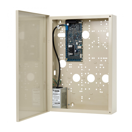
(8) Cable tie points (x34) (3) Tamper switch bracket slots (9) Transformer bracket mounting points (4) Tamper switch bracket mounting point (10) Transformer position (5) Door close points (11) Battery positions (6) Rear cable entry holes (x7) CDC4 Door Controller Installation and Programming Manual... -
Page 10: Transformer
(4) Earth tab (enclosure) (10) Transformer bracket (5) Fuse holder (11) Door (6) Earth tab (door) (12) Transformer The transformer has five tabs to provide an earth connection for the enclosure and installed devices. CDC4 Door Controller Installation and Programming Manual... - Page 11 2. Carefully remove the fuse holder using the tip of a flat head screwdriver. 3. Discard the active fuse and replace with the spare fuse. Figure 17 above. 4. Push the fuse holder back into the slot below the power inlet. CDC4 Door Controller Installation and Programming Manual...
-
Page 12: Earthing The Enclosure
The tamper kit can be installed so that an alarm is raised if the enclosure is opened or removed from the wall. Transformer retainer The transformer retainer is used to hold the transformer in place. CDC4 Door Controller Installation and Programming Manual... - Page 13 Figure 7: Tamper Bracket Assembly, and fastening in place with the nuts and washers provided. CDC4 Door Controller Installation and Programming Manual...
- Page 14 When the cable entry cut-out is not required (item 3), it can be blocked by inverting the cable entry guard plate. Place the tongue of the plate in the cut-out while the holes go over the studs and fasten in place with the nuts and washers provided. CDC4 Door Controller Installation and Programming Manual...
-
Page 15: Tamper
10. 7. Attach the two tamper leads to the tamper switch. 8. Attach the other ends of the tamper leads to the CDC4 door controller tamper switch input (see Figure 12 on page 13, item 9). CDC4 Door Controller Installation and Programming Manual... -
Page 16: Mounting Devices
3. Use the M3 screws supplied with the device to fasten it to the standoffs. Mounting locations A few examples of various size devices mounted in the housing are shown in the following figures. CDC4 Door Controller Installation and Programming Manual... - Page 17 Chapter 1: Installation Figure 9: Size A board devices INPUTS Figure 10: Size B board devices INPUTS CDC4 Door Controller Installation and Programming Manual...
- Page 18 Chapter 1: Installation Figure 11: Size F board devices INPUTS CDC4 Door Controller Installation and Programming Manual...
-
Page 19: Cdc4 Layout
( ) 1 ( ) 1 ( 0) (3 ) 8 (36) (14) (3 ) 7 (13) (11) ( ) 1 ( ) 1 INPUTS (12) (1) Mounting holes (2) AC power input terminals. CDC4 Door Controller Installation and Programming Manual... - Page 20 Auxiliary power +12 V DC −, −, − Auxiliary power GND S+, S− 8 Ω siren speaker or two 8 Ω siren speakers in parallel, or 12 V DC device and 1 kΩ 1/4 W resistor CDC4 Door Controller Installation and Programming Manual...
- Page 21 Chapter 1: Installation Terminals Terminal block Description − PANEL Advisor Advanced system data Black bus cable White D− Green T, C TAMP Panel tamper switches CDC4 Door Controller Installation and Programming Manual...
-
Page 22: Maintenance
This product may contain one (or more) sealed, rechargeable, lead-acid battery. Because removing a battery may affect the product’s configuration settings or trigger an alarm, only a qualified installer should remove the batteries. CDC4 Door Controller Installation and Programming Manual... - Page 23 When making voltage measurements at the battery terminals to establish battery state, healthy batteries that have not been discharged in the preceding 48hrs should measure >13.5 V CDC4 Door Controller Installation and Programming Manual...
- Page 24 Higher capacity batteries will have different terminal types, necessitating the use of adaptors or modifications to the leads. In these situations, sleeving or covers should be added to cover exposed metal on the battery tabs or connections. See also “Batteries” on page 24. CDC4 Door Controller Installation and Programming Manual...
-
Page 25: Mounting
If the following guidelines are followed, the system will give many years of reliable service. In addition to the following guidelines, during the installation of the CDC4 door controller, it is essential to follow any country-dependent local standard requirements applicable to the installation. Only a qualified electrician or other suitably trained and qualified person should attempt to wire this system to the AC mains or to the public telephone network. - Page 26 For the panel terminal connections, the recommended torque is 0.3 to 0.4 N·m. This torque setting is independent from the AWG (thickness) of the wires used. A value of 0.4 N·m is also the maximum allowed torque for this connector. CDC4 Door Controller Installation and Programming Manual...
-
Page 27: Earthing
If the wiring extends to separate buildings, more than one common earth system will be used. Use ATS1740 isolator/repeaters to isolate the system data bus. In this way the system is protected against variations in earth potential. CDC4 Door Controller Installation and Programming Manual... -
Page 28: Shielding
(6) Advisor Advanced control panel (2) Building 2 (7) System data bus (3) Mains power with local earth (8) Device in plastic housing (4) Earth and shielding (9) Device in metal housing (5) Mains power connector CDC4 Door Controller Installation and Programming Manual... -
Page 29: Dip Switch Settings
Chapter 1: Installation DIP switch settings CDC4 must be addressed as an expander in the range 1 to 12. Use the four- segment address DIP switch (Figure 12 on page 13, item 37) to set the address. It can only be installed on the system data bus 1. -
Page 30: Connections
Connections Power input AC power input for the CDC4 is provided via the two AC terminals. Power is typically provisioned from the transformer fitted to the enclosure in which the CDC4 is installed. The CDC4 AC voltage requirements are specified in “Specifications”... - Page 31 Battery charging current Nominal charging current is 600 mA. CDC4 Door Controller Installation and Programming Manual...
-
Page 32: Auxiliary Power Terminals
Output fusing and user current draw” on page 38. Caution: The siren type must be configured correctly in Downloader. Specifying a siren type of DC Volts when there is an 8 Ω siren connected to the CDC4 may damage the siren. System data bus... - Page 33 Chapter 1: Installation Devices can be connected to CDC4 via the 4-pin RS-485 terminals for bus 1 (Figure 12 on page 13, item 19) or bus 2 (Figure 12, item 18). Alternatively, devices can be connected to Bus 1 via the 4-pin plug-in RS-485 sockets (Figure 2 on page 7, items 17 and 20).
-
Page 34: Bus Termination
0 Ω indicates a short circuit in the cabling • 160 Ω or less indicates that too many devices are terminated • 220 Ω is good • 470 Ω or more indicates that not enough devices are terminated CDC4 Door Controller Installation and Programming Manual... -
Page 35: Lock Power
2-pin plug-in lock power sockets. Refer to Figure 15 on page 27 for example connections of 2-way lock power cables from CDC4 to an expander board (items A and C). Door lock relay wiring Figure 17 below details the wiring for the relay terminal blocks. -
Page 36: Inputs
Each pair of input terminals may be connected to a device such as a detector or door contact. CDC4 can monitor its input circuits for a few states (including active, normal, open circuit, short circuit, fault, anti-mask) depending on the settings. - Page 37 See “Output modules number” on page 83 for details. The PWR link (Figure 12 on page 13, item 14) enables CDC4 to power a connected output expansion module. Remove the link if the output card is powered from an external 12 V supply.
-
Page 38: Led Indications
Advanced system bus, the local buses (bus 1 and bus 2), and Ethernet activity. Table 3 below shows the LEDs for each of the items above. The numbers in the Item number column indicate the LED location on CDC4 as shown in Figure 12 on page 13. -
Page 39: Powering Up The Door Controller
Powering up the door controller Ensure the Advisor Advanced system bus is connected to the panel terminals (Figure 12 on page 13, item 8), and ensure the CDC4 address is set correctly (refer to “DIP switch settings” on page 23). -
Page 40: Defaulting The Door Controller
Chapter 1: Installation Defaulting the door controller You may want to perform a “default” to reset CDC4 to its factory default state and erase all programming. To default CDC4: 1. Remove power to CDC4 and wait for all LEDs to turn off. -
Page 41: Defaulting The Usb Communication Path
You may want to perform a “default” for USB. To default the USB: 1. Access the CDC4 panel PCB. 2. Fit test link 1 (Figure 12 on page 13, item 35) momentarily, and then remove the link. CDC4 Door Controller Installation and Programming Manual... -
Page 42: On-Board Memory Retention
Chapter 1: Installation On-board memory retention In the absence of any power source, the on-board capacitor storage will maintain the real-time clock and system configuration/logs for 5 days under typical circumstances. CDC4 Door Controller Installation and Programming Manual... -
Page 43: Standalone Current Draw
The local buses (bus 1 and bus 2) are not terminated and not active Note: Relay coil current forms part of the allowable user current draw. Refer to “Output fusing and user current draw” on page 38. CDC4 Door Controller Installation and Programming Manual... -
Page 44: Output Fusing And User Current Draw
1.0 A total Bus 2 0.5 A Lock power 1 1.9 A Lock power 2 1.25 A Consider the maximum current draw from the devices above when calculating the total user current draw. CDC4 Door Controller Installation and Programming Manual... -
Page 45: Operating Temperature
Chapter 1: Installation Operating temperature The operating room temperature for CDC4 is 0 to +50°C. It is recommended that if CDC4is to operate for prolonged periods in an operating environment with a room temperature above +40°C, derate the user current drawn from CDC4 according to the chart in Figure 20 below. -
Page 46: Cabling Requirements
The length of the bus cable run must not exceed 1.5 km. Power supply to bus devices Devices on the CDC4 buses may be supplied from the CDC4 12 VDC bus output. Use an external 12 V power supply when: •... -
Page 47: Specifications
Dimensions (W x H x D) 409 x 593 x 112 mm Weight 10.22 kg Fuses Mains, mains fuse M205 (5x20 mm) 1 A 250 VAC slow blow Battery 3AG/3AB (6x32 mm) 8 A 250 VAC slow blow CDC4 Door Controller Installation and Programming Manual... - Page 48 Chapter 1: Installation WARNING: Before removing the mains fuse, mains power must be disconnected (see “Mains power connection” on page 16). CDC4 Door Controller Installation and Programming Manual...
-
Page 49: System Functions
Chapter 2 System functions Summary This section lists and describes all functionality functions provided by CDC4 Door Controller. Content Function list 44 Operating modes 45 Doors 48 Lock types 49 Example door operation scenarios 50 Interlocking doors 52 Regions 54... -
Page 50: Function List
Chapter 2: System functions Function list Table 5 below provides an alphabetic list of CDC4 door controller functions and their description references. Table 5: Function list Function Reference “Alarm control” on page 59 Alarm control “Regions” on page 54 Anti-passback “Bus formats”... -
Page 51: Operating Modes
In addition to access control, CDC4 provides alarm control functionality in conjunction with an Advisor Advanced panel. CDC4 is polled as an expander on the first Advisor Advanced system bus. CDC4 Door Controller Installation and Programming Manual... - Page 52 Advisor Advanced control panel. Since the Advisor Advanced is responsible for the distribution of users, door groups etc. to CDC4, the numbers allowed are limited, as shown in Table 6 on page 45. History events, alarms, and CDC4 status are sent from CDC4 to the Advisor Advanced panel.
- Page 53 In this mode, management software downloads users, door groups, etc. directly to CDC4, allowing CDC4 to utilise its maximum capacities, as shown in Table 6 on page 45. CDC4 retains its own database of users, door groups etc. from the Advisor Advanced panel.
-
Page 54: Doors
Chapter 2: System functions Doors CDC4 can support up to four doors in standard mode, and up to eight doors in extended mode. The doors are numbered from 17 to 64 or from 17 to 112, depending on which operating mode CDC4 is working in. -
Page 55: Lock Types
Pre-Lock time: Once the door open input (door input 1) has been deactivated, CDC4 waits for the pre-lock time to expire before locking the door. If the door open input activates during the pre-lock time, the door is deemed open and the pre-lock timer is cancelled. -
Page 56: Example Door Operation Scenarios
Access time Waiting to shunt Shunt timer active Shunt continues unless cancelled Door open Pre-lock Post-lock (Input 1 active) time time Lock opened Relay 1 active for maglock (Relay 1 active) or drop bolt CDC4 Door Controller Installation and Programming Manual... - Page 57 Access time Waiting to shunt Shunt timer active Door Forced alarm Door open Pre-lock Post-lock (Input 1 active) time time Lock opened Relay 1 active (Relay 1 active) for maglock or drop bolt CDC4 Door Controller Installation and Programming Manual...
-
Page 58: Interlocking Doors
Interlocking may be used in a vault, for example. When programming a door on CDC4, there are two ways to specify an interlock door: either another door on the same CDC4, or a door on a separate controller. Interlocking doors on the same controller CDC4 has simplified configuration of interlocking doors on the same controller. - Page 59 • Wait for the CDC4 to confirm. CDC4 confirms with either 2 beeps if the credential has a right to access or 7 beeps in case of a wrong credential. The waiting time may be less than a second if no external interlocking is enabled or about 3 seconds if external interlocking is enabled.
-
Page 60: Regions
(HSU) present in them to allow any normal users inside. If a high security user leaves the region causing too few HSU present in it, an alarm is raised, preceded by prewarning time. CDC4 Door Controller Installation and Programming Manual... - Page 61 Set the following options in Doors > Alarm control tab: - Set the “IN alarm control” on page 110 to Alarm control via region count. - Set the “OUT alarm control” on page 110 to Alarm control via region count. CDC4 Door Controller Installation and Programming Manual...
-
Page 62: Panel Schedules
Override schedule and low security schedule (in door access options) • RTE schedule (in door RTE options) In standard mode, CDC4 uses the same panel schedules as the Advisor Advanced panel. Note: In case of CDC4 schedules only general data and time frames are downloaded to the device. -
Page 63: Door Schedules
Chapter 2: System functions Door schedules Up to 100 door schedules can be programmed in the CDC4, allowing for very flexible locking and unlocking as well as disabling and enabling doors. For more information on door schedules, see the “Overriding door state” section on page 69. -
Page 64: Macro Logic
The output event can be inverted. Macro logic is programmed in “Expander > Macro logic tab” described on page CDC4 Door Controller Installation and Programming Manual... -
Page 65: Alarm Control
Each alarm control level can be allocated a list of up to ten areas for arming and disarming. A CDC4 door can have up to six alarm control levels, which are then assigned to a door side (either IN or OUT) in any combination. Up to six alarm control levels can be assigned to a door side. - Page 66 Unlike keypads and reader connected to the control panel, readers connected to one of CDC4 local buses do not indicate the exit time during area set. To indicate the exit time by a buzzer, you must create a macro, which will activate the buzzer when the flag AreaInWarning is active.
-
Page 67: Bus Formats
Chapter 2: System functions Bus formats There are two local data buses on the CDC4 door controller. Each bus can have up to 16 RAS devices. Each bus can support readers other than ATS readers. Each bus supports the following protocols: •... - Page 68 To reset the encryption key used by an OSDP reader, the reader must be changed to Install Mode. Aperio The CDC4 door controller supports Aperio protocol. Note: Aperio protocol has a fixed baud rate of 19200 baud.
-
Page 69: Flexible Device Locations
• Address: If the device is connected to a DGP or RAS on one of the CDC4 local buses, then the address of this DGP or RAS must be specified. DGP addresses from 1 to 15 are defined to be on bus 1, and DGP addresses from 17 to 31 are defined to be on bus 2 (the DGP with address 16 is the CDC4 controller itself). - Page 70 The diagram in Figure 24 on page 65 shows devices attached to CDC4 and RASs/DGPs attached to its local buses that must be configured for use with the door.
- Page 71 DGP 1 RAS 1 DGP 2 OUT 1 (E) Bus 1 Bus 2 CDC4 OUT 6 DGP 17 OUT 5 (G) IN 3 RAS 17 IN 1-4 OUT 4 (F) IN 3 (A) CDC4 Door Controller Installation and Programming Manual...
-
Page 72: Input And Output Mapping
DGP or RAS on one of its buses), or can reflect the state of a CDC4 door (for example, a Forced door condition). An input mapping must be set up in CDC4 to map the state of the input or door to an input number in the range 1 to 32. - Page 73 CDC4 (either directly on-board, or attached to a DGP or RAS on one of its buses). An output mapping must be set up in CDC4 to map the output to an output number in the range 1 to 16. Activating the Advisor Advanced output number will activate the specified output attached to CDC4.
- Page 74 Door controllers may use the first 12 addresses on the Advisor Advanced system bus. Table 9 below lists the address of CDC4 (set via the CDC4 DIP switches), the expander number that the CDC4 controller is polled as, and the ranges of Advisor Advanced input and output numbers.
-
Page 75: Overriding Door State
4. The door programmed unlock schedule, set using configuration software. Scheduled actions Up to 100 door schedules can be programmed in CDC4, allowing for very flexible door locking and unlocking schedules. Door schedules have an active period (set via a start date and an optional end date). - Page 76 Door Lock action If the start action is Lock, then the door will lock at the start time and remain locked for the specified action duration (or indefinitely if there is no action duration configured). CDC4 Door Controller Installation and Programming Manual...
- Page 77 “Cancelling a start action” section above apply. Once the running action has been terminated, the door schedule record is removed from CDC4 so that no future iterations of the door schedule can occur.
-
Page 78: Random Lockout Time
Note: Users with the “Privileged” flag cannot cause a door lockout. A door random lockout time can be programmed in Downloader on the Access tab of the Doors form. See the “Random lockout time” section on page 101. CDC4 Door Controller Installation and Programming Manual... -
Page 79: Led Area Mapping For Door Readers
Advisor Advanced keypad. The LED area mapping is programmed in the Door reader dialog, accessed from the Readers tab of the Doors form. See the “LED mapping” section on page 109. CDC4 Door Controller Installation and Programming Manual... -
Page 80: Time And Attendance Readers
The readers may be used for time and attendance functionality (clocking on and off). There can be up to 32 RASs (readers or keypads) on the CDC4 local buses designated as time and attendance readers (see the “Time and attendance”... -
Page 81: Programming
This chapter explains how to use the Advisor Advanced programming menu to program the system. Content Recommended programming sequence 76 Downloader connection 78 Uploading default configuration 78 Upgrading firmware 78 Programming IP communications 79 CDC4 Door Controller Installation and Programming Manual... -
Page 82: Recommended Programming Sequence
Recommended programming sequence The following is a suggested programming sequence for a Door Controller: 1. Set the CDC4 DIP switches. See Chapter 1 “Installation > DIP switch settings” on page 23. 2. Default CDC4. See “Defaulting the door controller” on page 34. - Page 83 In the descriptions, Downloader is used for programming CDC4. Note: If ATS8600 will be used for management of CDC4, then some aspects of programming should not be done in Downloader, since ATS8600 will be responsible for those aspects. ATS8600 can be used to configure and manage: •...
-
Page 84: Downloader Connection
(1 to 12). 5. Set the Expander type to CDC4. New tabs will appear on the DGPs form to allow the operator to program CDC4. If desired, you can set up IP communications on CDC4. See the “Programming IP communications” section on page 79. - Page 85 Configure an IP communications path on the CDC4 for management software. Using Downloader, follow these steps: 1. On the expander list, select the CDC4 and select Comm paths tab to open the Comm paths form. 2. Select the required path and Click Browse “...” to configure it. In the Common Data Path tab, set Enabled to On.
- Page 86 Chapter 3: Programming CDC4 Door Controller Installation and Programming Manual...
-
Page 87: Menu Reference
Chapter 4 Menu reference Summary This chapter contains descriptions of all programming menu entries of CDC4 Door Controller. Content Expander 82 Expander tab 82 Details tab 82 Mapped inputs tab 85 Mapped outputs tab 87 Programming mapped inputs and outputs 87... -
Page 88: Expander
“Output type” on page 87. • Assigned RASs: Allows you to assign remote keypads on CDC4 or one of its buses to CDC4. Keypads must be assigned to CDC4 before they can be used. See the “Assigned RASs tab” section on page 88. - Page 89 12 V DC supply. Alternatively, the 12 V DC output can be used for a device that requires 12 V DC power when the CDC4 siren output is active. Duress mode...
- Page 90 Chapter 4: Menu reference Select the duress mode from the following options: • Disabled: Duress codes are not supported by the CDC4. • Increment last digit: The duress code is the user PIN with the last digit incremented by 1. For example, if the user PIN is 1234, then the duress code is 1235.
-
Page 91: Mapped Inputs Tab
The Mapped inputs tab shows a list of input mappings. Click the Browse “...” button to open the Mapped input dialog to edit the selected input mapping. On the Mapped input dialog, click the Remove button to remove the selected input data. CDC4 Door Controller Installation and Programming Manual... - Page 92 Chapter 4: Menu reference Note: CDC4 inputs are masked if they are not mapped to Advisor Advanced input numbers. Input no Enter a number in the range 1 to 32. The mapped input number is an index into the Advisor Advanced input numbering scheme. Thus, for the CDC4 with address 1 on the Advisor Advanced panel bus 1, mapped input numbers 1 to 32 correspond to Advisor Advanced input numbers 17 to 48.
-
Page 93: Mapped Outputs Tab
The mapped output number is an index into the Advisor Advanced output numbering scheme. Thus, for CDC4 with address 1 on the Advisor Advanced panel data bus 1, mapped output numbers 1 to 16 correspond to Advisor Advanced output numbers 17 to 32. See the “Input and output mapping” section on page 66 for information on output mapping. -
Page 94: Assigned Rass Tab
Assigned RASs tab Keypads and readers attached to one of the door controller local buses must be assigned to CDC4 on the Assigned RAS tab of the Expander form. Select the appropriate keypad and click Browse “...” to open the Assigned RAS form. -
Page 95: Assigned Dgps Tab
Configure an IP communications path on the CDC4 for management software. Follow these steps: 1. On the expander list, select the CDC4 and select Comm paths tab to open the Comm paths form. 2. Select the required path and Click Browse “...” to configure it. In the Common Data Path tab, set Enabled to On. - Page 96 Enables programming of up to four logic inputs, which can be a wide variety of conditions such as Door open too long, each corresponding to a specific DGP event. For each logic input, select the logic input type, then select the specific CDC4 Door Controller Installation and Programming Manual...
-
Page 97: Scheduled Actions Tab
On the Schedule form, click Remove to remove the schedule data. The following settings are available. Door number Enter the door number on the CDC4 to select the door. Enabled Select On to enable the door schedule. Start date Enter the start date for the active period. -
Page 98: Region/Hsu Configuration Tab
The minimum number of users required in the selected region. When the number of users in the region is below the programmed value, the output defined in “Below Low limit Output BUS” on page 93 is active. CDC4 Door Controller Installation and Programming Manual... - Page 99 The time (in seconds) for the warning timer. When the number of high security users is below the minimum, the warning timer starts. The timer resets if the number of HSU increases to the minimum threshold. CDC4 Door Controller Installation and Programming Manual...
- Page 100 The users are removed from the region every time the “Schedule” above is started (each segment becomes active). Release users from region on timezone end The users are removed from the region every time a segment of the “Schedule” above ends. CDC4 Door Controller Installation and Programming Manual...
-
Page 101: Alarm Control Level Tab
Arm: A user with the appropriate alarm group can arm the area. • Disarm: A user with the appropriate alarm group can disarm the area. Click the Delete button to remove the selected area data. CDC4 Door Controller Installation and Programming Manual... -
Page 102: Regions
High security function to allow users in the region under high security users (HSU) supervision. To define a region in a CDC4, follow these steps in Downloader: 1. Click the Regions item on the Panel programming form to open the Regions list. -
Page 103: Doors
The following settings are available. Lock type To support simple programming of complex door operation, CDC4 has various lock types, with associated inputs, outputs and timers. The lock type determines which inputs and outputs are used and how they are used. - Page 104 External input 1, 2, 3 CDC4 can check up to three external inputs for interlocking. If an input is wired up to an external controller door contact, then specify the input in one of the...
-
Page 105: Access Tab
If the time expires before the second badging, then the door is not unlocked and the operation must be recommenced. Enter the time in seconds. CDC4 Door Controller Installation and Programming Manual... - Page 106 Multi-badge time Note: Multi badge time can be set per door on the CDC4 door controller. If “Two-badge” on page 102 is enabled for the door, then this field defines the amount of time permitted between the first and second badges. If the time...
- Page 107 PIN if the door is configured to require card and PIN. Only a valid card or PIN code is needed to open the door when the schedule is valid. Click Browse “...” to open the Schedule list. Uncheck Disabled check box and then select an appropriate schedule. CDC4 Door Controller Installation and Programming Manual...
- Page 108 See the “Two badge unlock, one badge relock” section on page 103. OUT reader options The options for IN readers can also be applied to OUT readers. CDC4 Door Controller Installation and Programming Manual...
- Page 109 Door unlock after entry This field determines whether the override schedule (see the “Unlocked Schedule” section on page 101) takes effect immediately the schedule commences or after a user enters. CDC4 Door Controller Installation and Programming Manual...
-
Page 110: Shunt/Rte/Antipassback Tab
Input shunting: The door will be shunted and will generate a forced door alarm if it is left open (i.e. Door input 1 is active) longer than the programmed Shunt time (or Ext. shunt time, if applicable). CDC4 Door Controller Installation and Programming Manual... - Page 111 This is valid only when a region is programmed for the door. See the “In region” section on page 106 and the “Out region” section on page 106. Anti-passback violation is reported to management software. CDC4 Door Controller Installation and Programming Manual...
- Page 112 When a valid card or PIN is entered at the door reader, the region that the user is entering into is recorded against the user code. The system is then able to report an anti-passback violation. CDC4 Door Controller Installation and Programming Manual...
- Page 113 (via an access control level) are set, i.e. armed. If any of the areas assigned to the door are set then the RTE button will not unlock the door. CDC4 Door Controller Installation and Programming Manual...
-
Page 114: Readers Tab
Readers can be assigned to doors on the Readers tab of the Doors form. Note: If the reader is attached to one of the CDC4 local buses, then the appropriate RAS must be assigned to CDC4 on the Assigned RAS tab of CDC4, and polled. - Page 115 LEDs disabled: No LED control. Note: On readers with dual LED control lines, LED 2 may also be programmed to indicate other conditions via the CDC4 macro logic programming. LED mapping The LED mapping allows the operator to program which area number is assigned to the reader area LEDs, if applicable.
-
Page 116: Alarm Control Tab
OUT denied when set When set to On, a valid card or PIN will not open a door if any of the areas assigned to the door are set. CDC4 Door Controller Installation and Programming Manual... - Page 117 Alarm control levels tab (see “Alarm control level tab” on page 95). Open the list to assign alarm control levels to the door OUT readers. In the dialog, select the required alarm control levels. CDC4 Door Controller Installation and Programming Manual...
-
Page 118: Users
Advisor Advanced door groups for the CDC4 doors. A CDC4 in Extended mode uses CDC4 door groups, of which there can be up to 10,000. To add a door group to an Advisor Advanced panel, follow these steps: 1. - Page 119 3. Enter the required information on the User tab. 4. Ensure that the Door group field has a door group entry that has CDC4 doors. Click the Browse “...” button to open a door group selection dialog and assign the appropriate door groups.
- Page 120 Chapter 4: Menu reference CDC4 Door Controller Installation and Programming Manual...
-
Page 121: Troubleshooting
The chapter contains information on resolving known hardware and configuration problems. It also describes how to recover the system when the installer access is lost. Content Device troubleshooting 116 Door controller 116 Remote expanders — Models ATS1201, ATS1210, ATS1211, ATS1220 116 CDC4 Door Controller Installation and Programming Manual... -
Page 122: Device Troubleshooting
(mains or battery). The termination may be incorrect. See “Bus termination” on The expander appears to be going off-line and on-line (indicated by page 28. “Expander fail” on a LCD keypad) CDC4 Door Controller Installation and Programming Manual... -
Page 123: Appendix A Door Controller Events
Door disabled Door is disabled completely (from keypad or computer) Door two-badge inside [2] Two-badge access is required at the "IN” reader Two-badge access is required at the “OUT” reader Door two-badge outside CDC4 Door Controller Installation and Programming Manual... - Page 124 User with the “Privilege” attribute set can override the “Reader disabled” function. Table 11: Other macro event descriptions Name Description Input Output Area access Area in access (99 events, 1 per area) Area alarm Input(s) in alarm in area (99 events, 1 per area) CDC4 Door Controller Installation and Programming Manual...
- Page 125 Table 12: Macro event range for doors Name Input- I, Output –O, Both – I/O DOOR OPEN DOOR UNLOCKED DOOR LOCK DOOR OVERRIDE DOOR OVERRIDE INHIBIT DOOR DISABLED DOOR ENABLED DOOR READER DISABLED [4] CDC4 Door Controller Installation and Programming Manual...
- Page 126 DOOR RANDOM BIT [1] DOOR ACCESS DENIED DOOR ACCESS GRANTED DOOR ACCESS GRANTED TRACED DOOR ACCESS GRANTED 1ST BADGED DOOR ACCESS GRANTED 2ND BADGED DOOR ACCESS GRANTED 3RD BADGED DOOR FIRE OVERRIDE DOOR SECURE CDC4 Door Controller Installation and Programming Manual...
- Page 127 4192 4186 4287 4288 DGP Outputs [1] These events are not currently enabled. Table 14: Macro event range for data buses RAS offline DGP offline Bus 1 Bus 2 Bus 1 Bus 2 CDC4 Door Controller Installation and Programming Manual...
- Page 128 Appendix A: Door controller events CDC4 Door Controller Installation and Programming Manual...
-
Page 129: Appendix Bcdc4 Defaults
Shunt type Input shunting& DOTL Ext. shunt time 90 sec Shunt time 1 min Warning time 15 sec Anti-passback options Anti-passback Disabled RTE options RTE timed RTE schedule 0-(24 Hours) RTE reporting Enabled CDC4 Door Controller Installation and Programming Manual... - Page 130 On-board NONE Door On-board NONE Door On-board NONE Door On-board NONE RTE input Door On-board Door On-board Door On-board Door On-board Door On-board NONE Door On-board NONE Door On-board NONE Door On-board NONE CDC4 Door Controller Installation and Programming Manual...
-
Page 131: Glossary
A card is associated in the user configuration to a user by which the access rights are defined. Also referred to as a badge. Cards are used on readers or keypads with built-in readers. CDC4 Door Controller Installation and Programming Manual... - Page 132 Advisor Advanced control panel. Fire alarm An alarm triggered by fire or smoke detectors indicating a fire. A personal wireless device, which is used to perform programmed functions, for example, set or unset premises, open doors. CDC4 Door Controller Installation and Programming Manual...
- Page 133 Isolated: The zone has been inhibited from indicating normal or active status. It is excluded from functioning as part of the system permanently. • Masked: Detector is masked. • Fault: Detector reports an internal fault. CDC4 Door Controller Installation and Programming Manual...
- Page 134 The condition of an area where a change in the status of any zone (from normal to active) causes an alarm. An area or premise is only set when it is unoccupied. Some zones (like vaults) can remain armed continually. CDC4 Door Controller Installation and Programming Manual...
- Page 135 An electrical signal from a security device or a group of devices (PIR detector, door contact) to the Advisor Advanced system. Each device is identified by a zone number or a name. For example, zone 14, Fire Exit Door. CDC4 Door Controller Installation and Programming Manual...
- Page 136 CDC4 Door Controller Installation and Programming Manual...