
Related Manuals for ZyXEL Communications 2864 Series


Summary of Contents for ZyXEL Communications 2864 Series
- Page 1 2864 Series Modem User’s Manual Document No.: 8406, Rev. 1.0 ZyXEL COMMUNICATIONS CORPORATION...
-
Page 2: Limited Warranty
Limited Warranty ZyXEL Communications Corporation warrants to the original retail purchaser that this product is free from defects in materials or workmanship for a period of two (2) years from the date of purchase. If, during the warranty period, and upon proof of... - Page 3 Notice: ZyXEL COMMUNICATIONS CORPORATION does not assume any liability arising out of the application or use of any products, or software described herein, neither does it convey any license under its patent rights nor the patent rights of others. ZyXEL COMMUNICATIONS CORPORATION further reserves the right to make changes in any products described herein without notice.
- Page 4 Trademarks mentioned in this manual are used for plain informational purpose. Trademarks are properties of their respective owners. U-Modem , ZFAX and ZyXEL are trademarks of ZyXEL Communications Corporation. Smartmodem is a registered trademark of Hayes Microcomputer Products, Inc. MNP is a registered trademark of Microcom, Inc.
-
Page 5: Fcc Part 15 Information
FCC Part 15 Information This device complies with Part 15 of FCC rules. Operation is subject to the follow- ing two conditions: 1) This device may not cause harmful interference. 2) This device must accept any interference received, including interference that may cause undesired operations. This equipment has been tested and found to comply with the limits for a CLASS B digital device pursuant to Part 15 of the FCC Rules. -
Page 6: Telephone Company Requirements
Telephone number to which the modem is connected. • Manufacturer and Model Number: ZyXEL Communications Corporation Model Name You will find this information on the sticker label on the bottom case. The modem is connected to a public switched line using a USOC (Universal Serv- ice Order Code) RJ11C modular jack, and to a leased line using a JM8 jack. -
Page 7: Information For Canadian Users
Information for Canadian Users The Industry Canada (IC, formerly DOC) label identifies certified equipment. This certification means that the equipment meets certain telecommunications net- work protective, operational, and safety requirements. IC does not guarantee that the equipment will operate to a user’s satisfaction. Before installing this equipment, users should ensure that it is permissible to be connected to the facilities of the local telecommunications company. - Page 8 viii...
-
Page 9: Table Of Contents
Compatibility ......1-3 The 2864 Series Standard Features ....1-4 Additional specific features . - Page 10 External Modems ......3-1 Elite 2864 ....... 3-1 Elite 2864 Front Panel .
- Page 11 Resetting The Modem ......4-5 2864 QUICK START LCD Panel ....... 5-1 Panel Operation .
- Page 12 SETTINGS AND COMMANDS PROFILES Resetting from Profile ......7-6 Saving to Profile ......7-7 Profile Protection .
- Page 13 LEASED-LINE OPERATION Connecting to a Leased Line ..... . 12-1 Line Type ....... 12-1 Power Level .
- Page 14 ADVANCED VOICE CAPABILITY Voice Data Compression ......16-1 Automatic Detection of Voice, Fax and Data ....16-2 Voice States and Operation Modes .
- Page 15 GENERAL HINTS AND TIPS Activating Saved Settings upon Turning-on....19-1 Avoiding Low Throughput and Loss of Data ....19-1 Disabling Compression May Yield Faster Transfers .
- Page 16 APPENDICES GLOSSARY GLO-1 EIA-232D INTERFACE PHONE JACK PIN ASSIGNMENTS ZyXEL PARALLEL PORT INTERFACE V.25bis COMMAND SET STANDARDS ASCII Control Characters ......E-1 Selection of ITU-T standards .
-
Page 17: Introduction
The 2864 series of V.34 modems includes three sub-series of models, namely the Su- preme, Elite and Omni series. The Supreme and Elite series models have ISDN ca- pability or can be upgraded to have ISDN capability. The Omni series does not have ISDN capability. -
Page 18: How To Use This Manual
How To Use This Manual This manual describes the use of all models in the 2864 series and gives instruction for their installation and operation. The 2864I and 2864IU ISDN models come with a separate manual describing their ISDN operation. -
Page 19: Compatibility
Hints and Tips - Section five is the trouble-shooting and special advice section. Here you will find additional information on how to use a 2864 series modem with your computer, and some hints and tips relating to a number of communication software applications. -
Page 20: The 2864 Series Standard Features
V.26bis works in half-duplex mode on 2-wire dial-up line. †. 1800 Hz guard tone for V.22bis/V.22 answer mode, 6 dB below data signal level. The 2864 Series Standard Features • Synchronous/Asynchronous operations for external stand alone models and rack mount models. (Parallel port interface is for asynchronous transmission only) •... - Page 21 Blocks retransmitted • Blocks received in error • 20 2 LCD and directional keypads. (Supreme 2864 only) • G3 Fax sending and receiving capability with speeds up to 14400 bps. • Fax-Polling / Fax-Grouping. • Automatic detection of data or fax call.
-
Page 22: Additional Specific Features
Telephony Capability The 2864 series modem can detect the on/off-hook status or polarity change of the phone line connection and the attached telephone set. These will be reported as events in voice mode to the connected computer. The modem can also control and switch between telephone connecting to line and modem connecting to line. -
Page 23: Parallel And Serial Port Interface
firmware updates/upgrades for added and enhanced features. An 8 Mbit high-speed flash EPROM is standard on every 2864 modem (4 Mbit on Omni models). A firmware update is only an AT command to upload a new firmware file. -
Page 24: How To Become A Registered Owner
• one (1) 2864 series universal modem • one (1) power adapter (external model) • one (1) RJ11 telephone cable • one (1) JM8 leased-line cable (2864L model only) one (1) RJ45 ISDN telephone cable (2864I model only) • one (1) 2864 series user’s manual •... -
Page 25: Connecting To Your Phone
TION). Dial-Up Or Leased Line The 2864 and Omni 288 models may connect to 2-wire dial-up or leased lines only. The 2864L offers you a choice of connecting to 2-wire dial-up lines (more common- ly known as public lines) and 2/4-wire leased lines. To use the 2864L on a leased line, you must order and install a USOC JM8 jack. - Page 26 1–10...
-
Page 27: Modem And Fax Basics
Chapter 2 MODEM AND FAX BASICS This chapter is intended for those readers who want to know the details behind mo- dem and fax operations; what's going on behind the scenes. In addition to introduc- ing basic modem and fax terminology, this chapter helps users to understand and be able to utilize the available features. -
Page 28: Rs-232C Or Eia-232D/E
RS-232C or EIA-232D/E RS-232C is the Recommended Standard (RS) of the Electronic Industries Associa- tion (EIA), defining the serial communication interface between a DTE and a DCE. The 232 is basically a serial number for the defined standard. Sometimes it is neces- sary to redefine a standard, or to revise it. -
Page 29: Uart
1200 bps modems and Bell 103 for 300 bps modems. Everyone follows the ITU-T standards now for newer and higher-speed modems. ZyXEL 2864 series modems support all the above mentioned modem standards and are compatible with existing modems. Type of Telephone Line The commonly used phone service is a 2-wire dial-up line. -
Page 30: Intelligent Modem
nal transmission in both directions. This is the type of phone service most people have in their home or office. Since the same two wires are used for both transmitting and receiving signals, an echo of the transmitting signal will also be received and it is the modem receiver's task to remove the echo before demodulation. -
Page 31: At Command Set
BRI, Basic Rate Interface, is the ISDN service provided to a normal home or office. It consists of 2B+D data channels. A D channel offers a speed of 16Kbps for signal- ing information transmission. Each B channel is for user data transmission at 64Kbps. -
Page 32: V.25Bis Command Set
V.25bis Command Set V.25bis is a set of auto-dialing commands defined by the ITU-T. V.25bis supports both synchronous and asynchronous data interfaces and is mainly used in Europe and in IBM mainframe or mini-environments which use synchronous communica- tion. Error Correction In synchronous data communication, data is checked and corrected in the host by the so-called "link layer protocol"... -
Page 33: V.42Bis And V.42
V.42bis and V.42 V.42bis and V.42 are data compression and error correction standards set by the ITU-T. V.42bis has a better data compression efficiency than MNP-5 and is a more advanced compression scheme. V.42bis is used with V.42 for error correction. Xmodem, Ymodem, and Zmodem These are file transfer protocols. -
Page 34: Modem As A Fax
Modem as a Fax Modems can also be designed to include a fax transmitting and receiving function similar to a fax card. Since the modem's interface with the computer is the standard serial RS-232 interface, this interface is used for both modem and fax operations. Since the data throughput of a serial RS-232 interface is limited, only compressed fax image data should be carried through this serial interface. -
Page 35: Distinctive Ring
Distinctive Ring This is a service available from some phone companies in some areas of the USA and elsewhere. You can have several phone numbers on the same subscriber phone line. The phone company sends a different ring signal for each phone number assigned to the same line. -
Page 36: Automatic Redial / Call Hunting
Most modems will automatically redial a telephone number several times if a con- nection could not be established on the first try. The modems of the 2864 series also offer the ability to do cyclic redials of a set of up to 10 different numbers. -
Page 37: Modem Installation
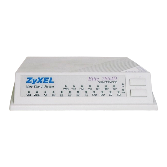
The Elite 2864 model is a V.34 modem with V.34/fax/voice capability and is up- gradeable to include ISDN capability. LEDs are used for all display purposes. Elite 2864 Front Panel Fig. 3.1 shows the front panel of the Elite 2864. There are 21 LED indicators and two key switches. ZyXEL... -
Page 38: Led Indicators
LED Indicators PoWeR on indicator; lights up when the modem‘s power is ON. TeST indicator; lights up when the modem is in test mode. FAX indicator; lights up when modem transmits or receives a fax. VOice mode indicator; lit when modem is in voice mode. SP * Serial Port active indicator;... - Page 39 Auto Answer indicator; lights up when the modem is in auto answer mode; flashes when modem rings. Carrier Detect indicator; lights up when a valid carrier is detected present on the line. Transmit Data indicator; lights up when your DTE/computer trans- mits data to the modem.
-
Page 40: Elite 2864 Rear Panel
Front Panel Switches There are two toggle switches on the Elite 2864 front panel. D/V (DATA/VOICE) A toggle switch that switches the modem on-line (off-hook DATA mode) or off-line (on-hook, Voice or Talk mode, the telephone set is connected to the line). The OH LED indicator will be turned on and off by this switch. -
Page 41: Connecting The Elite 2864
When you connect your 2864 to the power line, make sure you only use the ZyXEL power adapter that is supplied with this unit. Use of another adapter may not allow your modem to operate and could result in serious damage to the unit. -
Page 43: Turning On The Elite 2864
Elite 2864L Front Panel The Elite 2864L's front panel is exactly the same as the Elite 2864's except that the Elite 2864L has an LL LED indicator instead of the VO indicator. Leased-Line indicator; lights up when the modem is operating in the leased-line mode. -
Page 44: Supreme 2864L Front Panel
Fig. 3.3 shows the rear panel of the Supreme 2864L. The rear panel is similar to the Elite 2864’s rear panel shown in , except that the Supreme 2864L has three phone jacks. Besides the dial-up line RJ11 jack and the telephone connection RJ11 jack, there is also a JM8 leased-line jack. -
Page 45: Connecting The Supreme 2864L
Connecting the Supreme 2864L Please refer to the section Connecting the Elite 2864 on page 3–5. The descriptions therein also apply to connecting the Supreme 2864L. The Supreme 2864L has an additional leased-line jack for 2/4-wire leased line connection. Leave the leased-line jack unconnected if the leased line is not used. -
Page 46: Omni 288P And Omni 288S
DSR/PSL, PRP, PCP, EC, SQ, and OH. Explanations for the meanings of these LED indicators can be found in the table beginning on page 3-2 where the LED indica- tors of the same label are explained for the Elite 2864 model. There is only one push-button switch labeled D/V (DATA/VOICE) on the modem’s upper case near the lower right corner. -
Page 47: Omni 288P Rear Panel
The meaning of the Omni 288S LED indicators can be found in the table beginning on page 3-2 where the LED indicators of the same label are explained for the Elite 2864 model. Omni 288P Rear Panel Fig. 3.8 shows the rear panel of the Omni 288P. -
Page 48: Omni 288S Rear Panel
TO DTE This is a parallel port DB25 male connector for connecting to a PC’s parallel port or a printer’s Centronics compatible port. Microphone jack to plug in an external microphone. Used for voice recording purposes. Speaker jack to connect an external 8 Ohm speaker. An external speaker may be connected to replace the internal speaker and pro- vide better sound quality. -
Page 49: Connecting The Omni 288S
If the modem’s parallel port is always connected to a laser printer for fax printing, a computer/terminal can connect to the modem’s AUX RS232 serial port for issuing AT commands and reception of responses. This is good for configuration and mon- itoring operation without disconnecting the laser printer. - Page 50 3–14...
-
Page 51: Modem Operation
MODEM OPERATION Parallel or Serial Port Operation The 2864 models provide both a parallel port and a serial port for DTE connection, but only one out of three connection modes may be active at any time. The available modes are: •... -
Page 52: Pc Parallel Port Operation
PC Parallel Port Operation If the modem's parallel port is connected to a PC's parallel port, the PC can com- municate with the modem through the parallel port link. Be sure that your PC has a bidirectional parallel port. The modem's parallel port will not work with the old unidirectional parallel port. -
Page 53: Zyxel Parallel Port Adapter
ZyXEL is developing a special parallel port adapter that will make parallel port trans- fers much faster between a PC and the Elite 2864. The speed limitation in this case will be determined by how fast and how efficient the PC software program can han- dle the data. -
Page 54: Firmware Update/Upgrade
Firmware Update/Upgrade The 2864 series modem uses 4Mbit flash EPROM(s). The firmware in flash EPROM can be updated by uploading a file from the locally connected DTE. There is no need to open the modem case or use a programming device. The firmware is distributed in a file with the following naming conventions:... -
Page 55: Dram Upgrade
For the Supreme models, pressing the MENU key (the UP arrow key) while turning on the modem will have the modem execute the kernel program. You can also use the ATUPA command to upload the firmware file. In this case you can simply dump the firmware file to modem after typing the ATUPA command. - Page 56 On the internal card model, short the TS2 jumper with a plug, then power up the computer. The modem will be reset and will run a self-test. Printable characters will be shown on the computer screen. The TS1 LED should be continuously ON. If the LED flashes, the number of flashes indicates the error number corresponding to the error message listed at the beginning of chapter 18.
-
Page 57: 2864 Quick Start
It then waits for commands from a computer/terminal or any key pad op- eration from the front panel. On the LCD screen, there are four on-screen buttons: Dialing operation with submenus Redial last number Originate mode on-line Answer mode on-line Chapter 5 2864 QUICK START 5–1... -
Page 58: Panel Operation
The cursor is blinking above one of these on-screen buttons - a dark rectangle which may be moved using the keys next to the display. The modem also displays the cur- rent status and settings in the idle screen: Information Link Option Link Speed Error Control... -
Page 59: Double Arrows On The Screen
LED status screen has five status indicators - DCD, DSR, CTS, RTS, and SQ. These status indicators are identical to the LED indicators of the non-LCD modems. Val- ues in one of the other screen displays may give much more detailed information than some of these status indicators;... -
Page 60: Dial Memory
Dial Memory The first menu of the dialing directory is DIAL MEMORY. Pressing the ENTER key will cause the following screen to appear: #01: 1234567 << >> SELECT MEMORY Equivalent AT Commands View all stored phone numbers. AT&Z? n = 0 - 49; dial stored number. ATDSn The first stored number shown on the menu is the default dial number which can be selected from the DEFAULT DIAL menu. -
Page 61: Dial Number
ENTER. The blinking cursor will change into an underscore and will move to the next position on the right side of the colon(:). SELECT MEMORY will change to SELECT DIGIT. Press the left and right arrow keys to scroll through the valid digits and char- acters for dialing. -
Page 62: Repeat Last Dial
When you want to switch from modem to voice communication, simply lift up the handsets of both sides and press the ENTER key while the blinking cursor is on the H or Hang Up. The LCD display will show DISCONNECTING ? to ask for a confir- mation. -
Page 63: Dialing Messages
Dialing Messages Dialing will cause the following screen to be displayed on the LCD: The dialed phone number will be displayed on the second line of the 20 2 LCD screen. If the number exceeds 20 digits, only the first 20 digits/characters will be dis- played. -
Page 64: Display Unit
If a connection has been made, the LCD will display the actual connected status. These are data state screens: V.34 28800 V42b H>> 55820 51324 AS <RIGHT> << RG= 0 ED = 128 CL= 0 <LEFT> On-line Status Screen 1 Status Link Option Line Speed... -
Page 65: Panel Lock
On-line Status Screen 4 Status FRN ( Fast Rate reNegotiation) Granted FRN Requested Blocks Retransmitted FCS (Frame Check Sum) Errors Pressing the left or right arrow key in any one of the ON-LINE STATUS screens will cause the LCD to scroll through the four screens. We will discuss the ON-LINE STATUS screens 2, 3, and 4 in more detail in chapter 18. - Page 66 5–10...
-
Page 67: Modem Parameter Settings
MODEM PARAMETER SETTINGS This chapter explains how to view and set various major modem parameters using the Supreme 2864L CONFIGURATION menu tree. The non-LCD model users can also consult this menu tree for available parameter options, but must use the equiv- alent AT command to set the parameter. -
Page 68: Parameter Selection
Parameter Selection Press the left or right arrow key to view and scroll the available parameters. Only the parameters currently in effect have the equal sign (=) before their respective selec- tions, otherwise a colon (:) appears, meaning that this parameter choice is a selecta- ble option. -
Page 69: Terminal Options
TERMINAL OPTIONS DATA FORMAT + ASYNC AT&M0 SYNC DATA AT&M1 DIRECT AT&M2 SYNC AT&M3 DATA FORMAT defines the methods your modem employs to exchange data with the local DTE and the remote DCE. CHARACTER LENGTH AT*C0 AT*C1 AT*C2 AT*C3 Note: The character length includes the start, data, parity, and stop bit(s). - Page 70 DTE RATE + FIXED AT&B1 FOLLOWS AT&B0 LINK RATE Note: If you wish to keep your DTE rate fixed, you should choose a buff- ered transfer. (see DATA FORMAT) DTR OPTIONS IGNORED AT&D0 108.1 AT&D1 + DTR / 108.2 AT&D2 108.2 + RST AT&D3 Note:...
-
Page 71: Command Echo
RTS OPTIONS + IGNORED AT&R1 CTS TRACKS AT&R0 Note: Effective only in synchronous mode. This setting is ignored in asyn- chronous mode. RTS is always used as a hardware flow control sig- nal in this case. DSR OPTIONS + ALWAYS ON AT&S0 DATA SET AT&S1... -
Page 72: Modem Options
12000 9600 7200 4800 2400 1200 460800 MODEM OPTIONS LINK OPTIONS + MULTI-AUTO AT&N0 V.33 14400 AT&N1 V.33 12000 AT&N2 V.32 9600T AT&N3 V.32 9600 AT&N4 V.32 4800 AT&N5 V.29 9600 AT&N6 V.29 7200 AT&N7 V.29 4800 AT&N8 V.27b 4800 AT&N9 V.27b 2400 AT&N10... - Page 73 V.22b 2400 AT&N14 V.22 1200 AT&N15 V.21 300 AT&N16 V.32b 14400 AT&N17 V.32b 12000 AT&N18 V.32b 7200 AT&N19 B212A 1200 AT&N24 B103 300 AT&N25 V17 G3 FAX AT&N32 ZyX 19200 AT&N34 ZyX 16800 AT&N35 ZyX 14400 AT&N36 ZyX 12000 AT&N37 ZyX 9600 AT&N38 ZyX 7200...
- Page 74 QUALITY ACTION AUTO RE- AT*Q1 TRAIN + ADAPTIVE AT*Q2 RATE DISCONNECT AT*Q3 NORESPONSE AT*Q0 DEFAULT DIAL PH0 - PH49 AT*D0 AT*D49 DIAL BACKUP + DISABLED AT*B0 PH0 - PH49 AT*B1 AT*B50 GUARD TONE (For V.22 and V.22bis answer mode operation). + NONE AT&G0 RESERVED...
- Page 75 RDL REQUEST GRANT AT&T4 + DENY AT&T5 LLINE TX POWER (Leased LINE) 0 to -15 dBm AT*P0 AT*P15 PHONE JACK + SINGLE RJ11 AT&J0 MULTIPLE AT&J1 RJ12/13 MAKE/BREAK RATIO + 39% / 61% AT&P0 33% / 67% AT&P1 Note: Controls the ratio of Make (Off-hook) and Break (On-hook) interval for pulse dialing.
- Page 76 PANEL LOCK + UNLOCK AT*L0 LOCK AT*L1 Note: When the panel key is locked, it can only be used to view menu items but not to make changes. You can use the PANEL LOCK menu to lock the key, but you cannot unlock the key from this menu. Press the left and right buttons simultaneously , or use AT*L1 to unlock the key.
-
Page 77: Error Control
ERROR CONTROL CONTROL LEVEL Level NONE AT&K0 MNP4 AT&K1 (MNP3) MNP4 + AT&K2 MNP5 V.42 (MNP4) AT&K3 + V.42(b) + AT&K4 MNP4(5) Note: S38.5=1 disables MNP5 with no interference to other settings. FLOW CONTROL DISABLED AT&H0 + CTS / RTS AT&H3 LOCAL XON/ AT&H4... -
Page 78: Audio Options
Note: Only the expedited break is implemented in transmission, but all types of break are accepted in reception. AUDIO OPTIONS SPEAKER CONTROL ALWAYS OFF ATM0 + ON UNTIL ATM1 CONNECT ALWAYS ON ATM2 DIALED TO ATM3 CONNECT SPEAKER VOLUME 0 - 7 ATL0 ATL7 RING VOLUME... -
Page 79: Profiles
The 2864 series modems let you save up to 4 sets of configurations which are called profiles. You can save each entire modem configuration in the non-volatile EEP- ROM memory for later use as default settings, or you can use it as the power-on de- fault. - Page 80 … S115=000 S116=000 S120=000 S121=000 S125=000 S126=000 Current settings are the active settings which will effect the modem's functions until the power is turned OFF. You can temporarily change a setting in this set and use it, but the setting will be lost when you turn the power off. AT&V1 Profile 0 Settings...
- Page 81 Error Control Flow Control Quality Action Line Type AT&V2 Profile 1 Settings... &B1 &C1 &D0 &G0 &S0 &X0 &Y1 s000=000 s001=000 s005=008 s006=003 s010=007 s011=070 s015=130 s016=000 s020=001 s021=050 s025=000 s026=000 s030=000 s031=017 s035=034 s036=000 s040=000 s041=000 s045=100 s046=028 s050=000 s051=000 s055=000 s056=000...
- Page 82 Error Control Flow Control Quality Action Line Type Terminal Keyboard Aborting Auto Handshake AT&V3 Profile 2 Settings... &B1 &C1 &D2 &G0 &S1 &X0 &Y1 s000=000 s001=000 s005=008 s006=003 s010=007 s011=070 s015=130 s016=000 s020=001 s021=154 s025=000 s026=000 s030=000 s031=017 s035=032 s036=000 s040=000 s041=000 s045=100...
- Page 83 Sync Clock Line Type AT&V4 Profile 3 Settings... &B1 &C1 &D0 &G0 &S0 &X0 &Y1 s000=000 s001=000 s005=008 s006=003 s010=007 s011=070 s015=130 s016=000 s020=001 s021=018 s025=000 s026=000 s030=000 s031=017 s035=032 s036=000 s040=000 s041=000 s045=100 s046=028 s050=000 s051=000 s055=000 s056=000 s060=000 s061=000 …...
-
Page 84: Resetting From Profile
AT&V5 Factory Settings... &B1 &C1 &D2 &G0 &S0 &X0 &Y1 s000=000 s001=000 s005=008 s006=003 s010=007 s011=070 s015=130 s016=000 s020=001 s021=178 s025=000 s026=000 s030=000 s031=017 s035=032 s036=000 s040=000 s041=000 s045=100 s046=028 s050=000 s051=000 s055=000 s056=000 s060=000 s061=000 … s115=000 s116=000 s120=000 s121=000 s125=000 s126=000... -
Page 85: Saving To Profile
PROFILE 0 ATZ0 PROFILE 1 ATZ1 PROFILE 2 ATZ2 PROFILE 3 ATZ3 FACTORY ATZ4 DEFAULT Selecting profile n will reset the modem and load user profile n. Profile n is also set as the power-on profile. Saving to Profile You can save your current settings to one of the four user profiles. If you want to modify one of the profiles, recall it as the active settings, then use the panel menu or AT command to do modifications. -
Page 86: Resetting Profiles
Note that only profile 0 can be protected. Setting S35 bit 6 in profile 0 will also protect the supervisor password. If this bit is set, the supervisor password cannot be reset to the default ZyXEL by a modem hard- ware reset (see chapter 18). -
Page 87: Status Registers
(see chapter 7). The 2864 series modems are provided with 128 S-registers from S0 to S127. S0 to S11 are standard AT S-registers, and S12 to S127 are mostly bit-map configured. - Page 88 For example, if you want to set S38 bit 3 to 1 for a specific application, you may either use ATS38.3=1 (simple) or use the following method (difficult): Note: The values used in the example below differ from the actual values in the S-register and are used for demonstration purposes only.
-
Page 89: S-Register Descriptions
S-Register Descriptions The descriptions for each S-register follow. In most bit-mapped S-registers, the default bit value is 0 (which is the normal situation) and only the non-default situa- tion is described. Some reserved bits are for factory use and the user should not change them. - Page 90 Register Default Min. Note: The numerical values of the ASCII codes are always given as deci- mals. If you enter values from the LCD front panel, you must con- vert these values to hexadecimal (hex) values. Max. Description Sets the number of seconds the modem will wait for a carrier.
- Page 91 ZyXEL-specific Registers S12 Reserved. S13 Bit-mapped register; default: 0: Code Bits Bin. S14 Bit-mapped register; default: 2: Code Bits Bin. &M0 (7,6) &M1 &M2 &M3 &X0 (5,4) &X1 &X2 &L0 (3,2) &L1 &L2 &T4 &T5 S15 Bit-mapped register; default: 130: Code Bits Bin.
- Page 92 Code Bits Bin. (4,3) Note: Character length includes start bit, data bits, parity, and stop bit(s). Code Bits Bin. (1,0) S16 Test status register; default: 0: Code Bits Bin. &T0 &T1 &T2 &T3 &T6 &T7 &T8 Note: This S-register may not be set directly and may not be read while a test is in progress.
- Page 93 S17 Bit-mapped register; default: 18: Code Bits Bin. (7,6) (4,3, 0000 0 2,1) … … *P15 1111 30 Note: The secondary channel is only available in models with network management capability. S18 Set DTE speed for auto answer; Default: 0: Same value format as S20 (exception: set to 32 for 230400 bps).
- Page 94 Code Dec. &N6 &N7 &N8 &N9 &N10 &N11 &N12 &N13 &N14 &N15 &N16 &N17 &N18 &N19 &N24 &N25 &N32 &N34 &N35 &N36 &N37 &N38 &N39 &N42 &N43 &N44 &N45 &N46 &N62 &N63 &N64 Description V.29 9600 V.29 7200 V.29 4800 V.27bis 4800 V.27bis...
- Page 95 Code &N65 &N66 &N67 &N68 &N69 &N70 &N71 &N72 &N73 Note: Not all models support all modes. Check the compatibility table in chapter 1 for available modes. S20 DTE speed (auto-detected from AT command); default: 1: Dec. Description 230.4 Kbps 76.8 Kbps 38.4 Kbps 16.8 Kbps...
- Page 96 S21 Bit-mapped register; default: 178: Code Bits Bin. &D0 (7, 6) &D1 &D2 &D3 &R0 &R1 &C0 &C1 &S0 &S1 (2, 1) S22 Reserved. Dec. Description The modem ignores the DTR signal, DTR is always assumed to be ON. 108.1; DTR OFF-ON transition causes dial of the default number.
- Page 97 S23 Bit-mapped register; default: 105: Code Bits Bin. (5,4,3) &P0 &P1 S24 Bit-mapped register; default: 138: Code Bits Bin. (7,6,5) Dec. Description The modem returns result codes. (Default) The modem does not return result codes. (See also S40b1) Displays result code in numeric format. (See also S35b7) Displays result code in textual format.
- Page 98 Code Bits Bin. (3,2,1) S25 DTR detection delay; Default: 0: Specifies in units of 10ms the minimum time that the DTR signal must be OFF in order to be detected. If S25=0, the delay time is 4ms. S26 RTS/CTS delay; Default: 0: Sets the delay, in 10 millisecond units, between RTS and modem's CTS response in synchronous mode.
- Page 99 Code Bits Bin. &K3 &K4 S28 Bit-mapped register; default: 68: Code Bits Bin. &B0 &B1 &G0 (5,4) &G1 &G2 &Y0 (3,2) &Y1 &Y2 &J0 &J1 S29 Default dial phone number pointer; default: 0: Use AT&Zn=<number> to store a phone number at address n. Code Dec.
- Page 100 S30 Dial-backup phone number pointer; default: 0: Code Dec. 1-50 Note: When the leased line has become unoperational, the modem will automatically switch to dial line and the originate mode modem will dial the number according to the pointer saved here if dial backup was enabled;...
- Page 101 Code Bits Bin. S36 Bit-mapped register (Security function control): default: 0: Code Bits Bin. (7,6,5) Note: In security type 1, the remote site must be a ZyXEL modem. In security type 2, the remote site can be any other brand of modem. Dec.
- Page 102 Remote configuration control: Code Bits Bin. (4,3,2) *Wab *Rab *. Remote digital loopback request must also be granted. (AT&T4). S37 Bit-mapped register; Default: 0 For remote configuration using the panel menu: (See *W ab , *R ab ) Code Bits Dec.
- Page 103 Code Bits Bin. (2,1) S39 Bit-mapped register, default: 32: Code Bits Bin. (7,6) (1, 0) S40 Bit-mapped register, default: 0: Code Bits Bin. Dec. Description CD tracks the carrier. (Default) The CD on/off sequence follows the UNIX standard. CD is turned ON before the con- nection message is sent and CD is turned OFF after the last DCE response is sent.
- Page 104 Code Bits Bin. Note: Bits (6,5,4,3) enable ring detection on a combination of four ring types. All zeroes enable ring detection on any ring longer than 100ms. Please refer to Chapter 13 for details on EDR operation. S41 Bit-mapped register, default: 0: Code Bits Bin.
- Page 105 Code Bits Bin. S43 Bit-mapped register, default: 8: Code Bits Bin. (6,5,4) S44 Bit-mapped register, default: 0: Code Bits Bin. Dec. Description Disables DATA/VOICE button switch. Disables V.17 fax in calling mode, no effect on answering mode. (See &N0 and &N32) Disables escape sequence in answer mode.
- Page 106 Code Bits Bin. (1, 0) Delay during which the CND silence detection is disabled. Unit is 20ms; default: 87: (See also S46) CND silence detection interval. To process the CND signal, silence must be detected for the specified interval. Unit: 20ms; default: 3. Reserved.
- Page 107 Code Bits Bin. S49 Bit-mapped register, default: 6: Code Bits Bin. (6,5,4) (3 - 0) … Inactivity timer in 10-second units. The modem counts when there is no data flow in or out of the RS-232 serial port. A connection is disengaged when the counter reaches the preset value.
- Page 108 Code Bits Bin. (1,0) S52 Bit-mapped register, default: 0: Code Bits Bin. (6,5) (4,3) (2,1,0) Reserved. Reserved. Reserved. Hook flash time in 10ms units. A value of zero activates the standard specification of the country the modem is approved in; default: 0. S57 Bit-mapped register, default: 0: Code Bits...
- Page 109 S58-S70 Reserved. S71 Bit-mapped register (fax printing and storing control), default: 0: Code Bits Bin. (7,6) +FZF (2,1,0) Reserved. S73 Bit-mapped register (fax printing control), default: 0: Code Bits Bin. (7,6) (5,4) (1,0) Note: S-registers S70 through S79 are reserved for function control; S100 through S127 are reserved for ISDN functions.
- Page 110 8–24...
-
Page 111: At Command Set Summary
AT COMMAND SET SUMMARY An AT command is a command issued by the computer/terminal to the modem through the asynchronous computer-modem interface in asynchronous data for- mat. AT commands control the modem's behavior and actions. To send an AT command from a computer to the modem, you must be running a communication software and the modem must be in command state. - Page 112 Dials the last-dialed number. Dials the number stored in EEPROM at location n(0-49). S44.3=1 enables cyclic dialing. If the first dial is not successful, the modem will cycle dial through the first ten numbers stored in memory. Disables character echo in command state. Enables character echo in command state.
- Page 113 The modem returns a result code but quiet after answering on a RING. (See also S42b2) Sets S-register r to value n; n must be a decimal number between 0 Sr=n and 255. Displays value stored in S-register r. Sr.b=n Sets bit b of S-register r to value n. (n is a binary digit: 0 or 1) Sr.b? Display value of bit b of S-register r.
- Page 114 Result Codes for ATV0 ATV1 CONNECT 76800 CONNECT 115200 CONNECT 230400 CONNECT 460800 CONNECT 921600 CONNECT 307200 CONNECT 153600 CONNECT 102400 CONNECT 61440 CONNECT 51200 CONNECT 624000 CONNECT 124800 CONNECT 62400 CONNECT 41600 CONNECT 31200 CONNECT 24960 CONNECT 20800 CONNECT 33600 CONNECT 28800 CONNECT 26400 CONNECT 24000...
- Page 115 *. Data compression included. /SREJ is appended if a V.42 connection with selec- tive reject is established. **. When more than one type of Distinctive Ring is turned on (S40b3-6), RING n will be reported, n=Ring type (1-4). ***. Use S42b6 to disable RINGING result code. Examples: Error control level is from NONE to V.42b.
-
Page 116: Extended At& Command Set
Escape sequence code, entered in data state, wait for modem to return to command state. Basic command summary help. Extended AT& command summary help. &$ Extended AT* command summary help. Extended AT& Command Set DTE/DCE rate follows link rate. (If the communication software &B0 package has auto baud rate detection, please turn it ON.) (See also S44b6) - Page 117 No error control. &K0 MNP4 (includes MNP3). &K1 MNP4 + MNP5. (See also S38b5, S41b0) &K2 V.42 + MNP4. &K3 V.42 + V.42bis, compatible with &K2 . (Default) (See also S38b5) &K4 Normal 2-wire dial-up line. (Default) &L0 2-wire leased line. &L1 4-wire leased line.
- Page 118 V.21 &N16 V.32bis 14400/12000/9600/7200/4800 &N17 V.32bis 12000/9600/7200/4800 &N18 V.32bis 7200/4800 &N19 Bell212A 1200 &N24 Bell103 &N25 V.17 FAX 14400/12000/9600/7200 &N32 V.29 FAX 9600/7200 V27.ter FAX4800/2400 ZyX 19200ZyXEL 19200 &N34 ZyX 16800ZyXEL 16800 &N35 ZyX 14400ZyXEL 14400 &N36 ZyX 12000ZyXEL 12000 &N37 ZyX 9600 ZyXEL 9600 &N38...
- Page 119 Pulse dial make/break ratio= 39%:61%. (Default) &P0 Pulse dial make/break ratio= 33%:67%. &P1 CTS tracks RTS, response delay is set in S26. &R0 The modem assumes that RTS is always ON, ignores the changes. &R1 (Default) Note: &Rn controls the synchronous mode operation only. In asynchro- nous mode, CTS/RTS are used for flow control.
-
Page 120: Extended At* Command Set
The terminal provides synchronous transmit clock signal. (External &X1 clock from pin 24 of EIA-232D.) The receiving carrier provides synchronous transmit clock signal. &X2 (Remote or Slave clock to pin 15 of EIA-232D.) Destructive break, expedited. (Destructive break clears the buffer, &Y0 expedited break is sent immediately.) Non-destructive break, expedited. - Page 121 Enables type 2 security, with password check and call back; remote site enters the call-back number. Note: 1. The command *Gn requests supervisor password checking. 2. In security type 1, the remote site must be a ZyXEL modem. 3. In security type 2, the remote site can be any other type of modem.
- Page 122 Leased-line auto-handshake on answer mode. *P0-15 Sets leased-line transmission power level, range from 0 dBm to -15 dBm (Default = -9 dBm); range from -12 dBm to -27 dBm if S35b3 is set. The maximum transmission power for Omni 288P and 288S is -9dBm and -3dBm, respectively.
-
Page 123: Error Control And Data Compression
Every block is framed by a start flag (01111110) and an end flag (01111110). The maximum data block size used in the 2864 series is 256 bytes. The maximum number of outstanding blocks without acknowledgement is 31 for 128-byte blocks. These values are adjustable according to the modem on the other side. -
Page 124: Data Compression
2864 series modems support both V.42bis and MNP5 data compression protocols. Data compression needs an error-free data link to work correctly, otherwise the cor- rupted compressed data stream will ruin the decompression process. -
Page 125: Run-Length Encoding
The modem adaptively builds a dictionary of string tokens according to data that appears. 2864 series modems support a dictionary size up to 2K string tokens. The input data characters are combined and checked for a matching string in the dictionary. -
Page 126: Bidirectional Compression
300 bps to 460800 bps. What DTE speed is optimized for your application depends on how fast your computer and communication soft- ware can process the serial port data. 2864 series modems use certain controls and commands to enable the modem to optimize its performance. -
Page 127: Hints For High-Speed Operation
DTE. Turn ON the RTS and the modem will start sending data again to the DTE. In asynchronous full-duplex applications, the 2864 always responds to the RTS sig- nal as a flow control signal. The 2864 defaults automatically to this hardware flow control setting and it is a better choice. - Page 128 10–6...
-
Page 129: Synchronous Operation
SYNCHRONOUS OPERATION This chapter introduces you to the use of the 2864 series modem for synchronous oper- ation. Use the modem as a synchronous modem when it is connected to a synchronous computer or terminal. Be sure that the remote modem and system are also set to syn- chronous. -
Page 130: Half-Duplex Operation
Half-Duplex Operation For a half-duplex modem, the carrier only exists in one direction at any specific time. The carrier, the local CTS signal, and the remote CD signal will follow the RTS signal in a certain manner. Some communication software packages written for half-duplex modems rely on these RTS, CTS and CD signals. -
Page 131: Auto-Answer From Synchronous Mode
4) Dial from the panel. This is available only with an a LCD model’s LCD panel. Set the modem to synchronous mode, then select DIAL MEMORY or DIAL NUMBER to dial out the number you want. After the modem is connected, the modem will enter syn- chronous operation. -
Page 132: Setting Up A Zyxel Modem With The As-400
Setting up a ZyXEL Modem with the AS-400 This is a typical application where the user will use both the synchronous feature of the modem and the V.25bis option. Although we are using the IBM AS-400 com- puter as an example, other mid-range systems and mainframes should be able to use the same strings. - Page 133 4) To save the settings to a profile, press MENU once, and press the right arrow key until you see SAVE TO. Press ENTER and then the right arrow key to choose the profile you would like to save to; then press ENTER again to select it. 5) To activate these settings as your power-on default, you need to reset from this profile at least once.
- Page 134 11–6...
-
Page 135: Leased-Line Operation
LEASED-LINE OPERATION A leased line is a permanent telephone line connection between two fixed points. It can be dedicated copper wires or a leased telephone circuit from the telephone com- pany. The 2864L model supports 4-wire and 2-wire leased lines. 4-wire leased lines use one pair of wires to transmit data and a second pair to receive. -
Page 136: Power Level
Power Level The modem's leased-line mode transmission power level can be adjusted from 0 dBm to -27 dBm in 1 dBm increments. If a dial-up model is used for 2-wire leased- line connection, the transmission power is limited to -9dBm for the Omni 288P and to -3dBm for the Omni 288S. -
Page 137: Auto-Handshake
Auto-handshake If you want handshaking to occur automatically upon power-up, you have to save the leased-line configuration to the power-on profile. How to designate a profile to be a power-on profile is described in chapter 7. Please remember to set the hand- shake mode before you save the configuration. -
Page 138: Aborting From Leased-Line Operation
It will try these two alternatives indefinitely. If the dial backup attempt succeeds, the value of S-register S34 determines the interval of the dial backup connection before going back to check the leased line. The dial backup line continues to be used indefinitely. ATS34=0 Reattempts leased line after n minutes. -
Page 139: Special Functions
Security Function The 2864 series provides a security function, that (when enabled) prevents an un- authorized user from making a connection. Two types of security functions are pro- vided. Type 1 security is used when the remote modem is also a ZyXEL modem;... -
Page 140: Remote Configuration
Remote Configuration The 2864 series modems provide a remote configuration capability. Remote config- uration is provided as a profile by profile batch mode.When on-line, the remote modem's current configuration or one of its profiles can be read into one of the lo- cal modem's user profiles. - Page 141 Local profile modification is done by loading this profile as the active settings and then modifying and saving the active settings back to the profile. Then the connec- tion is reestablished and the profile is transmitted to the remote modem. Reading a remote profile b into a local profile a is done by the command: AT*Rab whereby...
-
Page 142: Caller Number Delivery(Cnd)
With CND service, the phone company's central office will send the coded caller information to the called station. This information is sent once between the first and second rings. 2864 series modems can decode this caller information and present it to the connected computer/terminal during the second ring period as part of the call progress ring message. -
Page 143: Distinctive Ring
CALLER NUMBER: 7135551414 or CALLER NAME: Jack Smith RING In the multiple message format, if the caller's number and name are available, the ring message will be: RING TIME: MM-DD hh:mm CALLER NUMBER: <Caller_ID> CALLER NAME: <Caller_Name> RING Following is an example: RING TIME: 04-28 12:30 CALLER NUMBER: 7135551414... -
Page 144: Extended Distinctive Ring
"ON" part (cadence) of the ring. The 2864 series modems can distinguish between up to four types of ring sig- nals and can be commanded to answer or not answer any one of these four types of ring signals. -
Page 145: Setting Up The Edr
telephone line for occasional fax or data calls; however, fax/data calls do come in from time to time. If a user lets the fax/data software application answer calls, voice calls will be missed; on the other hand, if a human being or an answering machine answers calls, fax or data calls may either be missed or the person who answers a call has to go through some trouble to get this call connected to the proper application. - Page 146 The EDR settings are defined in S-register S51. S51 Bit-mapped register, default: 0: Code Bits Bin. (7,6) (5,4) (3,2) (1,0) EDR detection (either CNG or DTMF tones) will be disabled once it occurs. However, a customer's program might not answer because the setting of the software may require multiple rings in order to answer.
-
Page 147: Application Example
This is supported by the communication software on the computer. The 2864 series modems support both asynchronous and synchronous V.25bis di- aling. However, the internal card supports only the asynchronous mode because it is asynchronous only with its built-in asynchronous serial port. The modem sup- ports the bit-oriented HDLC (High-level Data Link Control) synchronous proto- col which most synchronous communication links use. - Page 148 13–10...
-
Page 149: Cellular Mode Operation
Chapter 14 CELLULAR MODE OPERATION The ZyXEL 2864 series models are equipped with a special communication mode - cellular mode - which enables the modem to perform reliable high speed data trans- missions over cellular phone links. Although most ZyXEL modems can provide the cellular mode, the U-1496P portable modem is specially designed for mobile use. -
Page 150: Cellular Modems And Zycellular Technology
A cellular phone may be instructed to change its transmission power depending on its distance from the cell site station. The radio link will be interrupted for about 0.2 second. An effect similar to cell hand-off will occur. A particularly difficult cellular impairment for data communication is called multi- path fading. -
Page 151: Zyxel Zycellular Modes
ZyXEL ZyCellular Modes In addition to normal modem, fax, and voice operation modes, the following cellu- lar modes are offered in 2864 series modems: Mode Speed MULTI-AUTO V.34/ZyX modes/V.32bis/V.32/V.22bis/G3 FAX/Cellular Modes CELL 14400 14400/12000/9600/7200/4800 CELL 12000 12000/9600/7200/4800 CELL 9600 9600/7200/4800... -
Page 152: Cellular Modem Installation
If you are using a cellular phone data interface adapter, the following figures illus- trate three installation examples. The figures are illustrated with a U-1496P model. You can use a 2864 series modem, such as the Omni 288S, in the same way. 14–4... - Page 153 Fig. 14.1 is an example of a mobile phone that has a handset cradle and a separate transceiver and handset. Fig. 14.2 is an example of a mobile phone that has a separate transceiver and hand- set. 14–5...
- Page 154 Fig. 14.3 is an example of a one-piece hand-held mobile phone. Fig. 14.3: Example 3 - U-1496P with a hand-held phone Some newer cellular models, particularly the hand-held ones, have an audio jack that can connect the cellular phone's audio input/output to an outside headphone- microphone set.
-
Page 155: Fax Operation
The 2864 series modems include sif we fax functios, nsamlly adi rete fax rec- 5sn parallel porg, s well, s ad shand- eceiving and storing functiousring theopctioialDRAM add-ion. -
Page 156: Fax Command Sets
Fax Command Sets The 2864 series universal modems support four command sets for the fax function, the Class 1 command set, the TIA PN-2388 Class 2 command set, the TIA 592 Class 2.0 command set, and the ZyXEL Extended Fax AT command set. The Class 1 protocol uses the modem to transmit the fax data only. -
Page 157: Class 2 Command Set
Modulation values Value Modulation V.21 ch. 2 +FTH and +FRH support value 3 (V.21 ch. 2 / 300 bps) only. V.27ter V.27ter V.29 V.17 V.17 w/st V.29 V.17 V.17 w/st V.17 V.17 w/st V.17 V.17 w/st * w/st means with V.17 short training Class 2 Command Set The following Class 2 commands are supported and implemented per TIA PN2388 (8/20/90). - Page 158 Command Value +FBADMUL= 0-255 < > value +FBOR=n +FBUF? +FCIG =" " string +FCLASS=n +FCON +FCQ=n +FCR=n +FCTCRTY= 0-255 < > value +FDCC=vr,br,wd,ln, df,ec,bf,st vr=0 vr=1 br=0 br=1 br=2 br=3 Description Error threshold multiplier: Determines if the "Copy Quality OK" on the T.30 flow chart is met.
- Page 159 Command Value br=4 br=5 wd=0 wd=1 wd=2 ln=0 ln=1 ln=2 df=0 df=1 ec=0 ec=1 bf=0 st=0 st=1 st=2 st=3 st=4 st=5 st=6 st=7 +FDCS=vr,br,wd,ln, df,ec,bf,st +FDIS=vr,br,wd,ln, df,ec,bf,st +FDR +FDT (=df,vr,wd +FECM=n Description Bit rate: 12000 bit/s; V.17. Bit rate: 14400 bit/s; V.17. Page width: 1728 pixels in 215mm.
- Page 160 Command Value +FET=n +FLID=" " string +FLO=n +FLPL=n +FMDL? +FMFR? +FMINSP=n +FPHCTO= 0-255 <value> +FPTS=n Description Error correcting mode is enabled, handled by the DCE alone, including buffering of partial pages. End of page or document command: More pages; same document. End of document;...
- Page 161 Command +FREL=n +FREV? +FSPL=n All other +F commands are not supported, but the modem will respond OK. In many cases this means "don't care." See PN 2388 for command details. Class 2 Command Responses Response +FCFR +FCIG:" " string +FCON +FCSI:"...
- Page 162 Response Value n=70 n=90 n=100 +FNSC:" " HEX string +FNSF:" " HEX string +FNSS:" " HEX string +FPOLL +FPTS:n +FTSI:"string" +FVOICE Class 2 Flow Control Flow control is necessary to match the DTE-DCE data rate to the line signaling rate while transmitting or receiving Group 3 (T.4) data. In Class 2 fax mode, both hardware (RTS/CTS) and software (XON/XOFF) flow control are enabled.
- Page 163 +FCC=vr,br,wd,ln, df,ec,bf,st +FCLASS=n +FCO +FCQ=<rq>,<tq> rq=0 rq=1 rq=2 tq=0 tq=1 tq=2 +FCR=n +FCT=n 0-255 +FDR +FDT +FEA=n +FIE=n +FIP DCE capability parameter: refer to the +FDCC Class 2 command on page 15-4 for parameter settings. Service class selection: refer to the +FCLASS Class 1 command on page 15-2.
- Page 164 +FIS=vr,br,wd,ln, df,ec,bf,st +FKS +FLI=" " string +FLO=n +FLP=n +FMI? +FMM? +FMR? +FMS=n +FNR=rpr, tpr, idr, nsr rpr=0 rpr=1 tpr=0 tpr=1 idr=0 idr=1 nsr=0 nsr=1 Current session parameter: refer to the +FDCC Class 2 command on page 15-4 for parameter settings. Session termination command.
- Page 165 +FNS=" " string +FPI=" " string +FPP=n +FPR=n n>0 +FPS=n +FRQ=pgl, cbl pgl= 0-64 (HEX value) cbl= 0-FF (HEX value) +FRY=n 0-255 +FSP=n Non-standard byte string parameter. "string": string of hexadecimally coded octets. Local fax station ID string, for polling Rx. Packet protocol control parameter: Disables the DCE-DTE packet protocol.
- Page 166 Class 2.0 Command Responses Response Value +FCI:"CSI ID string" +FCO +FCS: vr, br, wd, ln, df, ec, bf, st +FET:<ppm> ppm=0 Another page next, same document. ppm=1 Another document next. ppm=2 No more pages of documents. ppm=3 Another page next, same document, procedure ppm=4 Another document next, procedure interrupt ppm=5 No more documents or pages, procedure inter- +FHS:<hsc>...
-
Page 167: Extended Fax At Commands
+FNC: " " NSC FIF string +FNF: " " NSF FIF string +FNS: " " NSS FIF string +FPI: " " CIG ID string +FPO +FPS:ppr, lc, blc, cblc, lbc +FTC: vr, br, wd, ln, df, ec, bf, st +FTI: "... - Page 168 The modem accepts the extended fax AT commands to set the modem mode and fax parameters. Besides the extended fax AT commands, the modem accepts all the other AT commands described in chapter 9. For instance, you can use ATD to make a fax call, or ATA to answer an incoming fax call.
- Page 169 Parameter Settings Sets maximum recording length: A4 (297mm ). Sets maximum recording length: B4 ( 364mm ). Sets maximum recording length: unlimited. Sets the minimum scan line time capability of the receiver: 20ms at 3.85 line/mm, T(7.7)=T(3.85). Sets the minimum scan line time capability of the receiver: 5ms at 3.85 line/mm, T(7.7)=T(3.85).
-
Page 170: Flow Control
This message includes the connection speed and the fax parameters. Snnnn Fax connection speed; nnnn is a 4-digit number representing the connection speed. nnnn =1440, 1200, 9600, 7200, etc., whereby 1440 and 1200 stand for 14400 and 12000. Vertical resolution; n = 0 or 1. Coding scheme;... -
Page 171: Parallel Receiving With The Fax Machine
The following flow control signaling is used while receiving a fax: CTS is not used when receiving a fax. RTS is used to inform the modem that the computer cannot accept data at this moment. The modem will not pass received data to the DTE if RTS is turned off. When finished receiving the fax message, the modem will turn off CD, then send a status report result code to the DTE. -
Page 172: Direct Fax Reception And Printing
2) Change one of the connection messages in the list to CONNECT FAX. 3) Set the external mail string to ZyXEL and give it an error level. 4) In your BBS batch file, if the error level matches the external mail, execute rcvfax 2 /p:comport [/w:workpath]. - Page 173 Use the serial port to enter the command: AT+FCLASS=Z The modem will enter into direct fax reception and print mode. Youalso need to set the S0 register to a finite number to enable auto-answering. To further detail oper- ation in Class Z mode, the special command AT+FZF has been implemented to de- fine the fax reception mode under Class Z operation.
- Page 174 The modem supports laser printers compatible with HP Laserjet-II printers or laser printers supporting the HP PCLII programming command language. This includes essentially all HP-compatible laser printers on the market. Different laser printers may have different print speeds. The fax receiving speed de- pends on the fax connection speed.
-
Page 175: Stand-Alone Fax Reception And Storing
Stand-alone FAX Reception and Storing With the DRAM option installed, you can have the modem receive faxes and store them in the DRAM. To work in this mode, you need to use the AT+FCLASS=Z command to set the modem to work in the Class Z mode. Also, you need to use the +FZF=n command to set the modem to work in one of the following modes: Fax to DRAM and printer, hangs up if data. - Page 176 You can use a computer with your existing fax software package to retrieve fax pages stored in DRAM. Use either the parallel port or the serial port to connect your com- puter to the modem and run your favorite fax program. When the fax program sets the modem to fax Class 2 or Class 2.0 mode, the modem will emulate fax calls com- ing in, have the fax program receive the fax calls, and then dump all stored fax pages to the fax program.
-
Page 177: Advanced Voice Capability
It also re- quires a lot of digital signal processing computation power. The ZyXEL 2864 series modems support four voice digitization schemes. A sum- mary of these four schemes is listed below:... -
Page 178: Automatic Detection Of Voice, Fax And Data
EDR (Extended Distinctive Ring) has been added to the firmware of all of the modems of the 2864 series. Refer to chapter 13 and S-regis- ters S40 and S51 regarding this feature. New capabilities or enhancements will be released in future versions of the firmware. -
Page 179: Voice Command State
In ZyXEL voice mode, three states exist that roughly correspond to the flow direction of the digitized voice data; the Voice Command State (no data transfer other than event re- ports), the Voice Transmission State (digitized voice data transfer from the DTE to the DCE), and the Voice Receival State (digitized voice data transfer from the DCE to the DTE). -
Page 180: Voice Data State
Voice Data State The DCE is in Voice Data State when the DCE is operating in voice mode and is communicating with a remote station or with one or more local devices which are capable of translating analog signals to voice (e.g., speaker) or translating voice to analog signals (e.g., microphone). -
Page 181: Events And Actions With Shielded Code
The ZyXEL 2864 series modems provide three ways to leave the Voice Receival State: A <DLE><!> shielded code is received from the DTE. - Page 182 <code> Event Report Description 1 (0x31) DTMF 1 2 (0x32) DTMF 2 3 (0x33) DTMF 3 4 (0x34) DTMF 4 5 (0x35) DTMF 5 6 (0x36) DTMF 6 7 (0x37) DTMF 7 8 (0x38) DTMF 8 9 (0x39) DTMF 9 0 (0x30) DTMF 0 A (0x41)
-
Page 183: Action Commands In Voice Data State
<code> Event Report Description L (0x4C) Loop current polarity reversal. This may indicate a hang-up or other events depending on the implementation of the central office. r (0x72) Ringback. b (0x62) BUSY. If the DCE continues to detect a BUSY signal, it may report this event repeatedly. -
Page 184: Voice At Commands
<ETX> (0x3) Ends Transmission Data State: The DTE sends this code to signify the end of the voice data from the DTE and cause the DCE to re- turn to the Voice Command State. The DCE will complete the transmission of the contents of its buffer before switching to the Voice Command State and returning the OK result code. -
Page 185: Supported Commands For Voice Mode Operation
Flow Control is necessary to match the DTE-DCE data rate to the line signaling rate and to the requirements of analog conversion of the voice signals and data. For ZyXEL 2864 series modems, both software XON/XOFF and hardware RTS/CTS flow control are used whereas the software flow control is the default setting. The DTE may turn off the flow control, but some other method must be used to avoid... - Page 186 DCE reports this result code when the DCE has determined upon detection of an answer-tone that the remote station is a data modem. The DCE may also issue this result code when the DCE has assumed that the remote station has gone off-hook by actions associated with the +VRA and the +VRN commands.
- Page 187 • AT+FCLASS=? The DCE returns permitted modes. The response is (with S57.4=1): 0,1,2,2.0,6,8,Z • AT+VLH=? This enables the DTE to inquire the hook status of the connected local phone. The DCE will return 0 for on-hook and 1 for off-hook status. •...
-
Page 188: Action Voice Commands For Voice Mode Operation
• AT+FLO? The DCE returns the current flow control setting, followed by the OK result code. • AT+FLO=? The DCE returns permitted flow control methods. The response is : 0,1,2 Action Voice Commands for Voice Mode Operation • AT+VIP The DCE will initialize all voice parameters to the default settings as follows: Parameter Silence threshold Hang-up code... - Page 189 This command causes the DCE to report the allowable tone frequency range and duration range. The ZyXEL 2864 series modems support two tones, both in the frequency range of 20 to 4800 Hz, and a duration range from 0 to 10 seconds. The...
-
Page 190: Configuration Commands For Voice Mode Operation
• AT+VTX This command causes the DCE to start the voice transmission process. The DCE begins the Voice Transmission Mode by returning the CONNECT result code to the DTE. After this report, the DCE accepts <DLE> shielded voice data from the DTE. - Page 191 The DCE returns the result code OK if the DCE accepts this command, or it re- turns the result code ERROR if the <level> parameter is out of range. • AT+VGT? The DCE returns the current transmission gain, followed by the OK result code. •...
- Page 192 The DCE returns the VCON result code (returns OK if S48.5=1) if the DCE ac- cepts this command, or it returns the ERROR result code if the <device> value is not permitted. • AT+VLS? The DCE will return the current I/O device followed by the OK result code. •...
- Page 193 The DCE returns the OK result code if the DCE accepts this command, or it re- turns the ERROR result code if the <interval> value is out of range. • AT+VRN? The DCE returns the current Ringback Never Appeared Timer interval value fol- lowed by the OK result code.
- Page 194 • AT+VSM=<cml> This command causes the DCE to select a compression method as follows: <cml> Compression Method Description ZyXEL 2-bit ADPCM (default) ZyXEL 3-bit ADPCM ZyXEL new 3-bit ADPCM ZyXEL 4-bit ADPCM The DCE returns the OK result code if the DCE accepts this command, or it re- turns the ERROR result code if the <cml>...
- Page 195 • AT+VTD? The DCE returns the current beep duration and pause interval setting followed by the OK result code. • AT+VTD=? The DCE returns the permitted values for the beep duration and pause interval. The response is: (0-255), (0-255) • AT+VDD=<dds>,<ddi> This command causes the DCE to set the DTMF detection threshold and the re- quired period of continuous DTMF tone detection before the DCE can report a DTMF event.
-
Page 196: Examples Of Voice Mode Operation
The DCE returns the OK result code if the DCE accepts this command, or it re- turns the ERROR result code if the <timer> value is out of range. • AT+VSY? The DCE returns the current resync timer value, followed by the OK result code. •... - Page 197 AT+VSM=4 AT+VLS=1 AT+VRX <DLE><!> AT+VLS=0 AT+FCLASS=0 Voice file playing via internal speaker. AT+FCLASS=8 AT+VSM=? 2;ADPCM;2;0;(9600) 3;ADPCM;3;0;(9600) 30;ADPCM;3;0;(9600) 4;ADPCM;4;0;(9600) VCON CONNECT <DATA> <DATA> <DLE><ETX> 16–21 Description Selects 4-bit ADPCM compression method. Activates the telephone set on the PHONE jack. Starts recording. Stops recording.
- Page 198 AT+VSM=2 AT+VLS=16 AT+VTX <DATA> <DLE><ETX> AT+VLS=0 AT+FCLASS=0 Voice file playing via line AT+FCLASS=8 AT+VSM=? AT+VSM=4 2;ADPCM;2;0;(9600) 3;ADPCM;3;0;(9600) 30;ADPCM;3;0;(9600) 4;ADPCM;4;0;(9600) VCON CONNECT 2;ADPCM;2;0;(9600) 3;ADPCM;3;0;(9600) 30;ADPCM;3;0;(9600) 4;ADPCM;4;0;(9600) 16–22 Description Selects the 2-bit ADPCM compression method. Activates internal speaker. Starts replay. Returns to the command state.
- Page 199 AT+VLS=2 AT+VTX <DATA> <DLE><ETX> AT+VLS=0 AT+FCLASS=0 Answering machine (Voice call) AT+FCLASS=8 AT+VSM=? AT+VSM=4 AT+VLS=2 AT+VTX <DATA> <DLE><ETX> VCON CONNECT 2;ADPCM;2;0;(9600) 3;ADPCM;3;0;(9600) 30;ADPCM;3;0;(9600) 4;ADPCM;4;0;(9600) VCON CONNECT 16–23 Description Connects to the line. Starts replay. Returns to the command state. Deactivates the line con- nection.
- Page 200 AT+VSM=2 AT+VRX <DLE><!> AT+VLS=0 AT+FCLASS=0 Answering machine (Fax call) AT+FCLASS=8 AT+VSM=? CONNECT <DATA> <DLE>b <DLE>q <DATA> <DLE><ETX> 2;ADPCM;2;0;(9600) 3;ADPCM;3;0;(9600) 30;ADPCM;3;0;(9600) 4;ADPCM;4;0;(9600) 16–24 Description Returns to the command state. Changes to 2-bit ADPCM for recording. Starts recording. The DCE detects a busy tone or a long period of quiet.
- Page 201 AT+VSM=4 AT+VLS=2 AT+VTX <DATA> <DATA> <DLE><ETX> AT+FCLASS=2 Switches to fax mode and answers the fax call… Note: If a modem data tone is detected - a <DLE>e response, the modem should be switched to data mode. Answering machine (Data call) AT+FCLASS=8 AT+VSM=? VCON...
- Page 202 AT+VSM=4 AT+VLS=2 AT+VTX <DATA> <DLE><ETX> AT+VSM=2 AT+VRX <DLE><!> (The DTE ought to delete this silence file.) AT+FCLASS=0 Switches to data mode and answers the data call… Note: If a modem data tone is detected - a <DLE>e response -, the mo- dem should be switched to data mode.
-
Page 203: Connecting A Telephone Set To The Modem's Phone Jack
Connecting a Telephone Set to the Modem's PHONE Jack A normal telephone set can be connected to the 2864 modem's PHONE jack and be used for recording and playback. A telephone set needs DC voltage and a current supply to work. This DC voltage is normally supplied through the phone line from the telephone company or a PABX. - Page 204 16–28...
-
Page 205: Network Management Capability
Chapter 17 NETWORK MANAGEMENT CAPABILITY When there are several modems installed at different places forming a modem net- work, it is desirable to monitor and control all of the modems and modem links from a central location. When there are hundreds of modems installed at one cen- tral location, it is also desirable to control and monitor all of the modems from the desk of a computer workstation. -
Page 206: Nms Capable Models
NMS Capable Models All ZyXEL rack models except the RE and RE+ models are NMS capable, but only the model with the N suffix has the secondary channel capability. A secondary channel is necessary for remote control and hierarchical control. For a large central site local control, the secondary channel is not needed. -
Page 207: Diagnostics
The 2864 series modems provide several diagnostic capabilities: • Power-on Self-Test • Analog Loopback Test • Analog Loopback with Self-Test • Local Digital Loopback Test • Remote Digital Loopback Test • Remote Digital Loopback with Self-Test • Line Condition Status Display •... -
Page 208: Analog Loopback Test (At&T1)
The Elite 2864 models have only LED indicators. The TST LED will be ON during the power-on self-test, and OFF after the test if everything is OK. The SQ LED flash- es if the test fails. -
Page 209: Analog Loopback With Self-Test (At&T8)
Bit Error Rate Meter. The left reader displays accumulated bit errors while the right reader displays accumulated bits sent. The Elite 2864 model’s TST LED flashes for any bit error and the Omni model’s EC LED flashes for any bit error. The Control Level field of the LCD model’s LCD screen will be indicated as ALBST, which stands... -
Page 210: Remote Digital Loopback Test (At&T6)
RLB, and that of the accepting modem will indicate LDL. The Elite 2864 modems will have the TST LED indicator ON during the test. This test can be initiated by either modem when the modems are on-line. -
Page 211: Line Condition Status Display
The 2864 modem can measure four major line impairments. From the impairment readings, you can understand the current line condition. The 2864 also logs line events over a long period, so you know what the line condition has been. We will... - Page 212 1-2 dBm of the actual value with relative accuracy. The receiver sensitivity specification for the 2864 is -43 dBm. Strong signal power could cause signal saturation in the channel and degrade the data validity. To avoid this situation, decrease the transmission power of the remote modem.
-
Page 213: Link Status Report (Ati2)
ON-LINE SCREEN 4 also has four counters recording the modem's actions and reac- tions. FRN (Fast Rate Negotitation) Granted (FG) The count of the granting of the remote modem's change rate (FRN) requests. Each request is an indicator of a changed receiving condition. FRN Request (FR) The count of the local modem's requests to change the rate. - Page 214 This Link Status Report is very helpful in finding out the link condition and what is wrong with the link, if anything. Following are the explanations for each item and the terminology used in this report. Chars Data characters transmitted between the DTE (computer/terminal) and the mo- dem.
-
Page 215: Round Trip Delay
Retrains Requested Number of times the local modem has requested a retrain. Each request is an indi- cator of bad receiving conditions. Retrains Granted Number of times retrains requested by the remote modem were granted. Link Duration Connection time in minutes. T401 Timeouts and T402 Timeouts These are for the manufacturer checking link layer operation. -
Page 216: Throughput Display
Each 2864 series model has a set of different firmware code. The firmware is not exchangeable between different models. Since flash EPROMs are used in the 2864 series modems, a firmware update is just a simple process of typing an AT command and uploading the firmware file. There is no need to open the modem case or program the EPROM. -
Page 217: General Hints And Tips
Avoid this by sending ATS35.1=1 to the modem. Avoiding Disconnections when Making a Data Call The modems of the 2864 series return a RINGING message when the remote mo- dem does not answer on the first ring. Some software packages confuse the RING-... -
Page 218: Calling From An Extension / Blind Dial
ING message with the RING message which the modems return when they detect an incoming call. These programs usually interrupt the connection and try to re- ceive the non-existing call. Disable the RINGING message with ATS42.6=1. Calling from an Extension / Blind Dial If your modem is connected to a large inhouse telephone system, it may be neces- sary to disable the modem's dial tone detection since many systems do not provide a standard dial tone. -
Page 219: The First Connection
THE FIRST CONNECTION Telecommunication using computers and modems is a simple task. You need only observe a few - important - parameters. This example shows you how to log into a BBS using the terminal program which is included with Microsoft Windows 3.x. As a Windows component, this simple terminal program has been widely distribut- ed and offers the basic features of a telecommunications package. - Page 220 4) From the menu Settings, choose Modem Commands and in the dialog, choose the parameter set Hayes. 5) Go to the dialog Settings - Terminal Emulation and choose DEC VT-100 (AN- SI). 6) In the dialog Settings - Terminal Preferences, activate Line Wrap from the Termi- nal Mode options.
-
Page 221: Zyxel Modems And A Pc
ZyXEL MODEMS AND A PC All of the modems of the 2864 series may be used with a PC. If you install the in- ternal PC card model, you don't need a serial cable. The modem's standard profiles should be just fine with most applications. If you are connecting to the modem’s parallel port, make sure that you have a bidirectional PC parallel port and use a 25-wire cable to make the connection. -
Page 222: Parallel Cable
Please consider this when you set up your modem's DTE to DCE speed. If you are using a ZyXEL 2864 modem’s parallel port for PC-modem communica- tion, setting the DTE speed has no actual physical meaning. The actual speed de- pends on how fast and efficient the Windows program can run. -
Page 223: Zyxel Serial/Parallel I/O Adapter Card
For high-speed PC to 2864 modem communication, ZyXEL produces the special I/O adapter card SP110AT. This card includes a serial port and a parallel port, each with special features, particularly when working with a ZyXEL 2864 series modem, for example: •... - Page 224 21–4...
-
Page 225: Zyxel Modems And Unix
Chapter 22 ZyXEL MODEMS AND UNIX Hints for Unix Setups Cable Please consult the documentation that came with your workstation to find the part number of or information on how to make a serial cable for your workstation. The cable should be a hardware-handshaking cable. Please refer to Appendix A for a complete list of signals provided by the modem its serial port. -
Page 226: Software Tips
Some archives also contain source files. You should suppress the modem's result codes (ATQ2) from the 2864 series mo- dems because some applications may be irritated by them. Disabling throughput averaging (ATS42.1=0) may speed up connections with powerful workstations. -
Page 227: Zyxel Modems And Apple Macintosh
ZyXEL MODEMS AND APPLE The external models of the 2864 series modems may be connected to an Apple Macintosh computer. You may use the standard modem settings, with one excep- tion: use AT&D0. Connector When you connect a ZyXEL modem to a Macintosh computer, make sure the cable is a hardware handshaking cable. -
Page 228: Cable
state of bit 3 (vsync) of the V1A1 chip's data register A determines which transfer method is used. If the bit is low, the serial port is used in asynchronous mode. If it is high, synchronous transfers are possible. You need special software which handles this bit. -
Page 229: Software For The Apple Macintosh
Software for the Apple Macintosh All terminal programs which make use of the hardware handshaking feature can be used on the Apple Macintosh. Such programs are readily avilable as PD, shareware or commercial software. One of the most powerful shareware programs available is ZTerm. - Page 230 23–4...
-
Page 231: Zyxel Modems And Ataris
ZyXEL MODEMS AND ATARIS All external models of the ZyXEL 2864 series may be connected to Atari comput- ers. The factory settings should work just fine with your Atari computer. Cable The standard Atari ST, Mega ST and Falcon 030 models provide just a single serial port, while the Mega STE and TT are equipped with 3 or 4 serial ports. -
Page 232: Hardware Tips
Hardware Tips While the 25-pin connector of the ST is 100% compatible with a PC connector and standard cables may be used, the maximum data rate on this port is restricted to 19200 bps. Kits are available which allow speeds of up to 57600 bps. If you want to use your Atari ST as an answering machine and use the ADPCM mode of your ZyXEL mo- dem, you must install one of these extensions. - Page 233 Using Rufus Some very old versions are irritated by the RINGING message during a dial-up if the RUFUS dial directory is used to initiate a call. Disable the RINGING message (ATS42.6=1) or even better, get a current version. Using Connect The shareware terminal software Connect makes use of the ZyXEL voice features.
- Page 234 24–4...
-
Page 235: Zyxel Modems And Amiga
ZyXEL MODEMS AND AMIGA You may connect any of the external models of the ZyXEL 2864 series to an Amiga computer. The default modem settings should work fine in most instances. Cable Among the Amiga computers, two versions of the serial port exist. The Amiga 1000 has a female 25-pin connector, the other models a male 25-pin connector. -
Page 236: Software Tips
Amiga *. not connected Software Tips A number of PD and shareware telecomunication packages, fax and voice software are available in BBSs and from the major online services. Hardware Tips Amiga computers run under a multi-tasking environment. Therefore you should lock the serial port, but do not lock it to baud-rates higher than 38400 bps on the low-end models. - Page 237 GLOSSARY Analog: Not digital. Analog quantities may have any value. Analog loopback test: Testing method in which the modem's analog output signal is connected to the analog input. Answer: In a connection between two modems, one modem works as the recipient (in answer mode) and the second modem as the initiator (originate mode).
- Page 238 Bit rate: Count of data bits transmitted per time unit. The framing bits needed for asynchronous transfer are also counted in the calculation of the bit rate. In general, the bit rate is ten times the character rate. bps: Unit of the bit rate; bits per second. Carrier: The carrier is a modulated tone and is used by the modem to transfer the data.
- Page 239 Data packet: Block of data which is framed by error control groups. A block consists of up to 256 8-bit groups. Data packets are used in synchronous transfer. Data pump: The important module doing modulation and demodulation for a modem. The data pump is decisive for the quality and the speed of a modem's transfer capabilities.
- Page 240 EEPROM: An Electronically Erasable and Programmable Read Only Memory. Such a device is used in ZyXEL modems to store settings and profiles. An EEPROM does not lose data when the modem is turned off. EIA: Electronic Industry Association (of North America); this organization was the first to draft a standard serial port (RS-232C).
- Page 241 each point to some short program sequence. An interrupt stops the currently run- ning program and the segment to which the vector points is executed. ITU-TSS: International Telecommunications Union - Telecommunication Stand- ards Sector. New name for the standard making organization CCITT. See CCITT. Jumper: A small device to close a contact.
- Page 242 PHONE: Jack to which a telephone set may be connected. Processing unit: A computer's brain. Here all the necessary calculations are per- formed. The modems of the 2864 series are basically specialized computers. Protocol, file transfer: Many protocols have been developed to ensure reliable data transfer at maximum speed, among them Xmodem, Ymodem, Zmodem and Ker- mit.
- Page 243 RS: Abbreviation of recommended standard. RTS/CTS: See CTS/RTS. RXD: Line for the received data on a serial port following RS-232C. Security function: Features of the ZyXEL modems which help deny illegitimate con- tacts to your computer system through telephone lines. Self-test: Ability of the modem to check its components and operations for faults.
- Page 244 ter: Old French word for three. Terminal Equipment: A computer running terminal software is used as terminal equipment in modem connections. Terminal program: A program which emulates the operation of a hardware terminal on a computer's screen and keyboard. Token: A token is a reencoding of information in less bits; basically an abbreviation. Transfer mode: Data can be transferred either synchronouosly or asynchronously.
- Page 245 Appendix A EIA-232D INTERFACE Signal ITU-TSS Signal Signal name name 108/2 108/1 Description Protective Ground (GND). Transmitted Data(TXD). Received Data(RXD). Request To Send (RTS). Clear To Send (CTS). Data Set Ready (DSR). Signal Ground (GND). Data Carrier Detected (DCD). Transmit Clock Signal (source: DCE). Synchronous Receive Clock.
- Page 246 A–2...
- Page 247 Appendix B PHONE JACK PIN ASSIGNMENTS Most models of the ZyXEL 2864 modem series feature two RJ11 phone jacks, one for the dial-up line connection (LINE) and one for an optional connection to a telephone set (PHONE). The signals on these pins are: The signals A and A1 are used with the KTS (Key Telephone System).
- Page 248 B–2...
- Page 249 Appendix C ZyXEL PARALLEL PORT INTERFACE Signal Signal name -STROBE DATA 0 DATA 1 DATA 2 DATA 3 DATA 4 DATA 5 DATA 6 DATA 7 -ACKNLG BUSY SLCT -ATFD -ERROR -INIT -SLCT IN Description Strobe pulse Data signal: bit 0. Data signal: bit 1.
- Page 250 Note: "Direction" column refers to the direction of the signal flow. When the 2864 ISDN or modem's parallel port is connected to a PC par- allel port, it emulates the printer side; when the ISDN/modem's par- allel port is connected to a printer, it emulates the adapter side.
- Page 251 Appendix D V.25bis COMMAND SET Syntax Command with Parameters CRN <dialstring> CRS n PRN n; <number> CFI XX LSN n; <number> Note: (1) Commands and parameters may be separated by spaces. (2) Dial modifiers: See the ATD command. (3) RLN is answered with several LSN displays. Every LSN corresponds to a memory location.
- Page 252 D–2...
-
Page 253: Ascii Control Characters
Appendix E ASCII Control Characters Dec. Hex 0x00 0x01 0x02 0x03 0x04 0x05 0x06 0x07 0x08 0x09 0x0A 0x0B 0x0C 0x0D 0x0E 0x0F 0x10 0x11 0x12 0x13 0x14 0x15 0x16 STANDARDS Character Key CTRL-@ CTRL-A CTRL-B CTRL-C CTRL-D CTRL-E CTRL-F CTRL-G CTRL-H CTRL-I... -
Page 254: Selection Of Itu-T Standards
Dec. Hex Character Key 0x17 0x18 0x19 0x1A 0x1B 0x1C 0x1D 0x1E 0x1F Selection of ITU-T standards X.1-X.15 International classes for users in public data networks. X.15 Definitions regarding public data networks. X.20-X.32 X.25 DTE/DCE interface for terminal equipment used in public networks working in packet mode. -
Page 255: Data Transmission Through Telephone Networks (V.1 -V.110)
X.400-X.430 X.400 Layer model - Service elements of the layers. X.430 Access protocols for terminals. Data transmission through telephone networks (V.1 -V.110) V.1-V.7 V.10-V.34 V.21 300 bps modems for use in public telephone networks. V.22 1200 bps duplex modems for use in public telephone networks and on leased lines. - Page 256 E–4...
- Page 257 INDEX &Bn 8-13 &Cn 8-10 &Dn 8-10 &Gn 8-13 &Hn 8-12 &Jn 8-13 &Kn 8-12 &Ln 8-5 &Mn 8-5 &Pn 8-11 &Rn 8-10 &Sn 8-10 &Tn 8-5 &Vn 7-1 &Wn 7-1 &Xn 8-5 &Yn 8-13 *Bn 8-14 *Cn 8-6 *Dn 8-13 *En 8-10 *Fn 8-16 *Gn 8-15...
- Page 258 automatic redial 2-9 AUX RS232 cable 3-13 averaging throughput 10-4 &Bn 8-13 *Bn 8-14 Bn 8-13 backspace character 8-3 backup 8-14 band noise 18-5 batch file 15-18 baud rate fixed 8-7 BBS 15-17 20-2 bidirectional parallel port 4-2 binary logic 8-2 Binkley 15-18 24-2 bit order 15-4...
- Page 259 communication asynchronous 2-2 synchronous 2-2 communication software 1-8 Communication Toolbox 23-2 companding 14-2 compatibility 1-3 compression 2-6 6-11 10-2 disable 19-1 voice data 16-1 configuration 9-10 Connect 24-3 connect 8-10 connect message fax 15-15 connection 20-2 cable 3-5 computer 3-5 first 20-2 ISDN 3-7 phone line 3-6...
- Page 260 EDR 8-22 timing 13-8 EDR detection 13-8 EEPROM 9-10 EIA 2-2 Elite 1-1 ISDN 3-7 Elite 2864 3-1 Elite 2864L 3-6 adaptive frequency encoding 10-3 string coding 10-3 end of document 15-6 end of page 15-6 EPROM 1-7 change 18-10...
- Page 261 fax-storing 15-21 FCC information v +FCLASS 15-14 features 1-4 file format 16-20 file transfer protocol 2-7 firmware 18-10 fixed baud rate 8-7 flash 19-2 flash EPROM 1-7 flow control 6-11 8-12 fax 15-8 fax AT 15-16 format result code 8-11 FOSSIL 4-2 adaptive frequency encoding 10-3 frequency offset 18-6...
- Page 262 &Ln 8-5 *Ln 8-13 Ln 8-11 LAPM 10-1 laser printer 15-20 leased line 6-10 12-1 leased-line 2-3 9-11 LED indicator 3-2 LED status screen 5-2 legal matter 2-10 liability iii line condition 8-19 18-5 line feed character 8-3 line type 6-10 link layer protocol 2-6 link options 6-6 link rate 9-7...
- Page 263 NOT 8-2 null-modem 2-2 20-1 octet 18-8 Omni 1-2 Omni models 3-10 on-line state 9-2 on-screen button 5-1 operation mode 1-3 OR 8-2 ORG/ANS 3-4 originate 5-5 9-11 OSSIL 4-2 P 8-11 page length 15-5 page width 15-5 panel 9-11 panel confirmation 12-4 panel function 3-1 panel lock 6-10...
- Page 264 Q1 15-16 Qn 8-11 quality action 6-8 *R 8-16 &Rn 8-10 radio link 14-1 rate change 18-7 RDL 8-5 RDL request 6-9 read S-register 8-1 rear panel Elite 3-4 Elite L 3-7 Omni 3-11 Supreme 3-8 receive level sensivity 8-22 recived signal power 18-6 recording 16-20 redial 2-10...
- Page 265 serial port 1-7 21-2 23-1 priority 21-3 speed 6-4 service class 15-4 parameter 6-2 setting 9-9 16-8 20-1 settings 19-1 save 7-7 shielded code 16-5 signal (data) carrier detected 6-4 break 6-11 data set ready 6-5 data terminal ready 6-4 request to send 6-5 signal processing 16-1 signal quality 3-2...
- Page 266 throughput 18-10 19-1 throughput averaging 8-19 TIA 15-2 time-limit 13-2 timer extension 8-18 timing 13-8 tone dial 9-3 spacing 8-4 total reset 4-5 trademarks iv transmission method 8-5 transmission mode 6-3 transmission power 9-12 radio 14-1 transmit clock 9-9 transmit power 6-9 14-4 trellis 8-15 U-1496 series 8-20...