
Related Manuals for ZyXEL Communications U-336S


Summary of Contents for ZyXEL Communications U-336S
- Page 1 U-336S User’s Manual Version 2.0 (Mar. 1997) ZyXEL & I CCESSING NTERNET NTRANET...
-
Page 2: Zyxel Limited Warranty
ZyXEL Limited Warranty ZyXEL warrants to the original end user (purchaser) that this product is free from any defects in materials or workmanship for a period of up to two (2) years from the date of purchase. During the warranty period, and upon proof of purchase, should the product have indications of failure due to faulty workmanship and/or materials, ZyXEL will, at its discretion, repair or replace the defective products or components without charge for either parts or... -
Page 3: Fcc Part 15 Information
The contents of this book may not be reproduced (in any part or as a whole) or transmitted in any form or by any means without the written permission of the publisher. Published by ZyXEL Communications Corporation. All rights reserved. Note: ZyXEL does not assume any liability arising out of the application or use of any products, or software described herein. -
Page 4: Information For Canadian Users
installed and used in accordance with the instructions, may cause harmful interference to radio communications. If this equipment does cause harmful interference to radio/television reception, which can be determined by turning the equipment off and on, the user is encouraged to try to correct the interference by one or more of the following measures: •... - Page 5 company’s inside wiring associated with a single line individual service may be extended by means of a certified connector assembly. The customer should be aware that the compliance with the above conditions may not prevent degradation of service in some situations. Repairs to certified equipment should be made by an authorized Canadian maintenance facility designated by the supplier.
-
Page 6: Contacting Zyxel
EletoMagnetic Compatibility. Contacting ZyXEL If you have questions about your ZyXEL product or desire assistance, contact ZyXEL Communications Corporation in one of the following ways: • Phone: In North America call between 8:00 AM and 5:00 PM PST at (714) 693-0808 Outside North America, you can dial +886-3-5783942 EXT 252 between 8:00AM and 5:00PM Taiwan time (GMT +8:00). - Page 7 For European versions and related files, use the address: ftp.zyxel.co.at • Postal Service: You can send written communications at the following address: ZyXEL Communications Corporation 6, Innovation Road II, Science-Based Industrial Park Hsinchu, Taiwan 300, R.O.C. ZyXEL Communications Inc. 4920 E. La Palma Avenue...
-
Page 8: Table Of Contents
Contents ZyXEL Limited Warranty ii FCC Part 15 Information iii Information for Canadian Users iv Contacting ZyXEL vi 1 Introduction 1 Unpacking Your Modem 1 Enclosed Equipment 1 Required Equipment 2 Becoming a Registered Owner 2 Modem Features 3 Standard Features 3 Intelligent Features 4 Fax Compatibility 5 Technical Specifications 5... - Page 9 Dialing and Answering Techniques 15 Dialing using the ATD Command 15 Auto-Answer and Hook Controls 16 Making Your First Connection 16 Quick Tips when issuing AT Commands 17 Modem Result Codes 19 Viewing S Register Values 20 Changing S Register Values 20 Non-Volatile Memory 21 Storing Phone Numbers 21 Dialing Stored Phone Numbers 21...
- Page 10 Dialing a Number 32 Manual Dial 32 Repeat Last Dial 33 Auto Answer 34 Dialing Messages 34 Panel Lock 37 V.25bis Command Set 38 Clock Options 39 RTS Options 40 Command State Options 40 Dialing from Synchronous Mode 41 Answering from Synchronous Mode 42 Auto-Answer 42 Manual Answer 42 5 Leased Line Operation 43...
- Page 11 Caller Number Delivery (Caller ID) 51 Distinctive Ring 54 Extended Distinctive Ring (EDR) 56 Setting Up EDR 57 EDR Application Example 58 7 Fax Operation 61 Fax Basics 61 Modem as Fax Machine 62 ITU-T T.30 Fax Protocol 62 Fax Command sets 63 Defining the Fax Command Sets 63 Class 1 Command Set 64 Class 2 Command Set 65...
- Page 12 Result Code Field Descriptions 125 Connect Strings for Error Corrected Connections 125 10 Diagnostics & Troubleshooting 128 Diagnostics 128 Power-On Self Test 128 Resetting The Modem 129 Loopback Tests 130 Indicator Lights 132 Line Condition Status Display 132 Trouble Shooting 134 AT Command Set Problems 135 Command Echo Problems 136 Answer Problems 137...
-
Page 13: Introduction
Introduction Congratulations on the purchase of your U-336S modem - one of ZyXEL's premier high-performance products. The U-336S modem is world renown for its ability to maintain ultra high speeds and clear, quality connections while communicating around the globe. If you do not find information on a specific topic, or if you would like more information about a topic covered in your User's Manual, please call ZyXEL Technical Support at 714-693-0808. -
Page 14: Required Equipment
Contact your dealer or the store where you bought the modem if anything is missing. Check the modem for shipping damages. If you find any damage, contact the shipping agency immediately. Retain shipping and cushioning materials for future storage or shipping needs. -
Page 15: Modem Features
not necessary for product repair/or replacement, save your dated invoice as proof of purchase. Modem Features No other 33.6 Kbps modem gives you so much for so little. Your modem is equipped with an array of standard and ZyXEL-famous Intelligent features designed to make your data communications faster, easier, and more convenient. -
Page 16: Intelligent Features
Intelligent Features • Automatic data, fax and voice call detection allows you to use a single telephone line to handle all three types of calls. • Asynchronous and synchronous modes for reliable serial data communication. • Fast retrain with automatic fall-forward and fall-back. Your modem will automatically fall back to lower speeds when communicating with slower modems and when encountering unstable or variable line conditions. -
Page 17: Fax Compatibility
Fax Compatibility • EIA Class 1, 2, and 2.0 Fax commands. • ITU-T V.17 G3: up to 14,400bps. • ITU-T V.29 G3: up to 9,600bps. • ITU-T V.27ter G3: up to 4,800bps. • ZyXEL Fax AT commands. Technical Specifications • Operating mode: auto-dial/answer. •... - Page 18 6 Introduction...
-
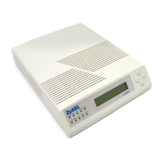
Page 19: Installation
Front Panel The figure below shows the front panel of the U-336S. There are 10 LED indicators, a 20 x 2 LCD display, and four key switches. Figure 2-1 Front Panel... -
Page 20: Front Panel Switches
The four arrow keys are for panel operations, allow intuitive menu tree operation and display modem status. Refer to Panel Operation on page 28 for details of menu key operations. Rear Panel Markings The U-336S rear panel is shown below: 8 Installation... -
Page 21: Power Jack
Figure 2-2 Rear Panel The following explains the connectors and switch on the rear panel. • POWER Power switch, turns the modem ON or OFF. • POWER JACK Input terminal for power adapter. • LEASED LINE Leased-line JM8 terminal jack, for connection to a 2/4-wire leased line. -
Page 22: Modem Connection
Modem Connection When you connect your modem to the power line, make sure you only use the power adapter that is supplied with this unit. Use of another adapter may not allow your modem to operate and could result in serious damage to the unit. This adapter is rated for direct connection to an AC power outlet and has a 2-meter cord. - Page 23 After performing the diagnostic tests, your modem will display the current modem settings on the LCD panel as shown below: Your modem is now ready for use. LINK OPTION ERROR CONTROL Multi-auto V42b D R O A 115200 AS LINE TYPE DATA FORMAT DTE RATE ANSWER MODE...
- Page 24 12 Installation...
-
Page 25: Basic Modem Operation
Understanding AT Commands The U-336S communicates asynchronously with computers using AT commands. AT commands are used to configure and control your modem. Commands are usually sent to the modem by way of communication software, but can also be entered manually by the user with the computer keyboard. - Page 26 Terminal” program. This program provides a simple method to manually enter AT commands so you can do such things as “customize” the settings of your modem, or store commonly used phone numbers. Once your modem is connected to your computer’s serial port and telephone line, open the Windows 95 “Accessories”...
-
Page 27: Dialing And Answering Techniques
Your modem responds This confirms that the modem and your computer are communicating correctly. To test the telephone line connection issue the manual answer command. Type: ATA<Enter> Your modem will pick up the phone line, and try to communicate. Normally, this command is only used to answer an incoming call made from another modem, thus the high pitched tone you will hear from the speaker. -
Page 28: Auto-Answer And Hook Controls
Pausing During Dialing: ATDT 9,,555 1212 O O N S8. D HE PAUSE TIME FOR EACH COMMA IS DEFINED BY EGISTER EFAULT IS SECONDS PER COMMA Dialing Without Waiting for Dial Tone: ATX0D, 555 1212 Originating a call using an Answer Tone: ATDT 555 1212,,,,,,R Redialing the Last Number Called: ATDL Waiting for Five Seconds of Silence:... -
Page 29: Quick Tips When Issuing At Commands
Start the terminal program by double-clicking the Test Connection icon. When the terminal window appears, enter the dial command with ZyXEL’s BBS as the phone number. Type: ATDT17146930762 <enter> (Omit the ‘1714’ if you are in this area code) The modem will go off-hook, dial the number, and after a few seconds of negotiation tones, you should be connected to our BBS. - Page 30 Terminates the current connection attempt, if pressed while modem is handshaking. Escape code sequence. Entered while the modem is in Data Mode. Returns modem to Command Mode. The U-336S supports several groups of AT commands: AT Command Set/Type Example Basic AT (Hayes compatible) ATB0 Basic AT$ (on line help) Extended AT&...
-
Page 31: Modem Result Codes
An OK result code means the AT command you sent was executed. If you receive an ERROR code, it means the command was invalid. The U-336S also provides result codes that show: • Whether or not a Dial Tone was detected when the modem originated a call. -
Page 32: Viewing S Register Values
modem uses. By default, your modem uses result codes equivalent to the ATX5 command. The result code options will be covered more thoroughly in later chapters. Viewing S Register Values Status registers (or "S-registers") contain values that determine the modem’s operating characteristics. Whenever you send an AT command to your modem, you are actually changing the value of an S-register. -
Page 33: Non-Volatile Memory
Non-Volatile Memory The U-336S has an amount of memory set aside for storing user information such as frequently used phone numbers and default command settings. The latter is particularly useful when using your modem to call a variety of different locations that require different settings. -
Page 34: Saving Settings And User Profiles
Saving Settings and User Profiles There are some cases where you may wish to save the settings you have made as the default settings that are recalled when your modem is powered up. The AT&WZ command selects the current settings as the power-on profile. There are four profiles that can be changed by the user, and one factory default profile. -
Page 35: Default Modem Settings For Pc's
SMARTDRV execution in your AUTOEXEC batch file. Default Modem Settings for PC’s The U-336S factory settings are configured for operation with PC type computers and communication software. In most cases, no additional settings will be required. The following are some of the... -
Page 36: Helpful Hints For Mac Computers
parallel port, each with special features, particularly when working with a ZyXEL modem, for example: The serial port is 16550-compatible for most communication software usage. It has a speed of up to 460.8Kbps and data loss errors will not occur when working with a ZyXEL modem's serial port. -
Page 37: Helpful Hints For Unix-Based Computers
readily available as PD, shareware or commercial software. One of the most powerful shareware programs available is ZTerm. Fewer programs are available to make use of the ZyXEL's fax features. One program which has found wide acceptance is Fax STF which can be installed like a printer driver allowing you to send faxes from almost any program which runs on your Macintosh. -
Page 38: Unix Software Tips
Depending on your Unix setup, the cable and software used, you may have to disable carrier detection using AT&C0. Unix Software Tips In order to use your ZyXEL modem from a terminal or an X- Windows application, you need a program such as Minicom or Seyon. -
Page 39: Lcd Panel Operation
LCD Panel Operation This chapter explains how to place and receive calls using the U- 336S front panel. An introduction to the panel operation of your modem is presented. Your modem comes with a menu driven 20 x 2 LCD display. All functions of the modem are displayed and selectable from this menu. -
Page 40: Panel Operation
computer/terminal or any key pad operation from the front panel. On the LCD screen, there are four on-screen buttons: Dialing operation with submenus. Redial last number. Originate mode on-line. Answer mode on-line. The cursor is blinking above one of these on-screen buttons, a dark rectangle which may be moved using the keys next to the display. -
Page 41: Menu Tree
register the chosen selection and is very similar to the Carriage Return key or Enter key on a standard keyboard. Menu Tree In command state, there are three main menu trees. The DIALING menu is the default, and can be accessed after the modem is powered on or reset. -
Page 42: Dialing
only find a double left arrow displayed, this indicates that your current item is the last item in that menu. Similarly, pressing the right arrow key at this point will cause the screen to wrap around to the first item. Dialing From the IDLE SCREEN (1) you can use the right or left arrow key to scroll through D, R, O, and A. -
Page 43: Storing A Number
AT&Z? View all stored phone numbers. ATDSn n = 0 - 49; dial stored number. The first stored number shown on the menu is the default dial number which can be selected from the DEFAULT DIAL menu. By pressing the left or right arrow key, you can view up to 50 different numbers stored in the memory. -
Page 44: Dialing A Number
underscore and will move to the next position on the right side of the colon. SELECT MEMORY will change to SELECT DIGIT. Press the left and right arrow keys to scroll through the valid digits and characters for dialing. Pressing ENTER will confirm the selected digit and cause the cursor to move to the next position. -
Page 45: Repeat Last Dial
Originate modem and who will be the Answer modem. Once an agreement is reached, use the left or right arrow key to select the O or A for Originate or Answer. Then press the ENTER key to start the modem handshaking sequence. Equivalent AT Commands: Go on-line in Originate mode. -
Page 46: Auto Answer
ATDL Repeat last dial. Repeat last command once. A> Repeat last command once, retry the last call up to 9 times. (country specific) Auto Answer Move to the STATUS REGISTER menu, and change the S0 value to the desired number of rings until the modem automatically answers. - Page 47 The modem will then return to the IDLE STATUS screen. If the phone company is ringing the remote modem, a RINGING message is sent to the terminal. Setting S42.6 = 1 will disable this RINGING result code. If any key interruption occurs (from the terminal or panel) and breaks in before the connection is made, the screen displays: ABORT......
- Page 48 Status Display Unit/Meaning Link Option V.34 Line Speed 28800 Error control V42b V.42bis Line Type Dial-up Line Data Format ASynchronous Instant Transmission 55820 bps; Blank in synchronous mode Throughput Instant Receiving 51324 bps; Link Speed in synchronous Throughput mode On-line Status Screen 2 Status Display Unit...
-
Page 49: Panel Lock
Status Display Unit Blocks Retransmitted FCS (Frame Check Sum) Errors Pressing the left or right arrow key in any one of the ON-LINE STATUS screens will cause the LCD to scroll through the four screens. We will discuss the ON-LINE -STATUS screens 2, 3, and 4 in more detail in chapter 0 Line Condition Status Display. -
Page 50: V.25Bis Command Set
However, viewing in the panel is not affected. This chapter introduces you to the use of the U-336S for synchronous operation. The modem can be used as a synchronous modem when it is connected to a synchronous computer or terminal. -
Page 51: Clock Options
Syntax Command with Description Parameters* CRS n Call request with number from memory, 0 # n # 49; n is the memory location. PRN n; Saves <number> to address n <number> (0 # n #49). RLN*** Requests list of all stored numbers. Ignores incoming call. -
Page 52: Rts Options
1. The internal clock is the one that suits most applications and is the default; in this case, the clock signal is generated by the sending modem. 2. The slave clock is used when in remote digital loopback mode. 3. The external clock is a signal generated by the sending DTE. INTERNAL AT&X0 The modem provides the clock and... -
Page 53: Dialing From Synchronous Mode
exchanges data synchronously in data state. SYNC AT&M3 The modem accepts synchronous command (V.25bis) and exchanges data synchronously with a remote modem. Dialing from Synchronous Mode 1. Dial from the terminal using asynchronous commands: Set &M1 and use asynchronous AT commands to dial the number. Once the modem is connected, the modem will enter synchronous operation. -
Page 54: Answering From Synchronous Mode
Answering from Synchronous Mode Auto-Answer Set the modem to synchronous mode. Set the S-register S0 to equal the number of rings before auto-answer occurs. Set it from the terminal (if &M1 is set) using the asynchronous AT command, or select the STATUS REGISTER menu to change the S0 value. Manual Answer Type ATA from the terminal (if &M1 is set). -
Page 55: Leased Line Operation
Your modem supports 2 and 4-wire leased lines. Connecting to a Leased Line The U-336S default line is a dial-up type (DL) which includes a separate leased-line jack. The leased line must be connected to the jack labeled LEASED LINE (located at the rear of the modem). -
Page 56: Leased Line Handshaking
AT-Command Description AT*P0 The default is -9dBm. The adjustable range is . . . from 0 to -15dBm, effective in leased-line AT*P15 operation only. If bit 3 of S35 is set, this range will change to -12 to -27dBm. Leased Line Handshaking In a typical dial-up connection, the originating modem dials the number and waits for the answering modem's carrier signal. -
Page 57: Leased-Line Dial Backup
AT-Command Description AT*M0 When operating over a leased line, modem will handshake in originate mode. (Default) AT*M1 When operating over a leased line, modem will handshake in answer mode. Leased-Line Dial Backup When a leased-line connection fails, the following actions may be taken by the modem: •... -
Page 58: Aborting From Leased-Line Operation
fails, the originating modem will go back to try the leased line connection. If this fails, it will try the dial-up line again. It will try these two alternatives indefinitely. If the dial backup attempt succeeds, the value of S-register S34 determines the interval of the dial backup connection before going back to check the leased line. -
Page 59: Special Functions
Special Functions This chapter describes special features of the U-336S, and offers instructions on how each is used. Security Functions Your modem provides a security function that prevents unauthorized users from making connections. Two types of security functions are provided. -
Page 60: User Passwords
• With level 1 security, the local modem will maintain the connection if the password is OK, otherwise the line disconnected. • With level 2 security, dial back the phone number corresponding to the dial-in password. The line simply disconnects if the password does not match. User Passwords Fifty user passwords may be defined. - Page 61 The following commands will enable different types and Verify: (Enter the new supervisor password again) ******** The command AT*Hn will modify the nth user password. You will be prompted to enter the supervisor password first and then be prompted to enter the nth user password. Levels of security: Command Function...
-
Page 62: Remote Configuration
Remote Configuration Remote configuration on the U-336S is provided as a profile by profile batch mode. When on-line, the remote modem’s current configuration or one of its profiles can be read into one of the local modem’s user profiles. This profile is modified locally and the line can be disconnected during this time. -
Page 63: Caller Number Delivery (Caller Id)
The remote profile read and write commands - *Rab and *Wab - only work in the on-line condition. The connection speed and mode do not matter. The remote modem must be set to accept remote configuration by executing the AT*F1 command. The AT*F0 command will set the modem up to deny remote configuration requests. - Page 64 There are two kinds of caller information message formats sent by the phone company. • One is the single message format which includes date, time, and caller ID. • The other is the multiple message format which also includes the caller name as registered with the phone company. The command ATS40.2=n is used to enable (n=1) or disable (n=0) the Caller ID detection function.
- Page 65 CALLER NUMBER: 7135551414 or CALLER NAME: Brent Harper RING In the multiple message format, if the caller’s number and name are available, the ring message will display both: RING TIME: MM-DD hh:mm CALLER NUMBER: <Caller_ID> CALLER NAME: <Caller_Name> RING Here is an example: RING TIME: 04-28 12:30 CALLER NUMBER: 7135551414...
-
Page 66: Distinctive Ring
Setting S48.0=1 will cause the modem to report CND information in its ASCII coded hexadecimal raw data format. The DTE software is responsible for explaining the data. O O N TR-NWT- LEASE REFER TO THE ELLCORE ECHNICAL DVISORY DOCUMENT 000030 FOR THE EXACT DATA FORMAT HE ABOVE ALLER... - Page 67 commanded to answer or not answer any one of these four types of ring signals. Following is a list of these four types of ring signals. These are the ring types used in the USA. The difference among the ring types is the two-second ON part of the ring signal. It comprises a long, double short, or triple short ring.
-
Page 68: Extended Distinctive Ring (Edr)
Extended Distinctive Ring (EDR) Extended Distinctive Ring (EDR) is a special feature designed for single telephone line home use to receive fax or data calls without interfering with regular voice calls. When most users install a fax/modem at home, they won’t subscribe to an extra telephone line for occasional fax or data calls;... -
Page 69: Setting Up Edr
tone and report RING to the software immediately. The software application can then issue commands to answer the call and receive the fax. If the remote caller is using a fax phone which does not send out a CNG tone and is waiting for a fax answer tone in order to press the START button, the caller can press a designated DTMF tone, which will activate the modem to report and subsequently be ordered to answer the fax call. -
Page 70: Edr Application Example
Bits Bin. Dec. Description Report RING six times. EDR detection (either CNG or DTMF tones) will be disabled once detection occurs. However, a customer’s program might not answer because the setting of the software may require multiple rings to answer. S51 bits 0-1 control the number of rings that the modem will report once the CNG or DTMF tone is detected. - Page 71 2. Set S51.0=1 to enable EDR and report RING twice. The modem will not report a normal RING and ZFAX will not answer a call unless EDR RING is reported. 3. Set S51.4=1 to enable fax CNG tone detection. It is reported as RING.
- Page 72 60 Special Functions...
-
Page 73: Fax Operation
Fax Operation The U-336S can be used as a fax machine. In the sections below, we will describe how the modem works as a fax machine, the ITU- T T.30 fax protocol, the Class 1,2, and 2.0 fax commands and ZyXEL extended fax AT commands. -
Page 74: Modem As Fax Machine
entity, or individual. In order to program this information into the fax function of your modem, please refer to the documentation of the fax software you will be using. Modem as Fax Machine Modems can also be designed to include a fax transmitting and receiving function similar to a fax card. -
Page 75: Fax Command Sets
9600 bps and will automatically fall back to 7200, 4800, and 2400 bps if the line quality is poor. Fax Command sets The U-336S supports four command sets for fax operation: • Class 1 command set • TIA PN-2388 Class 2 command set •... -
Page 76: Class 1 Command Set
formally approved version is the Class 2.0 command set, also called the TIA-592 standard. Class 1 Command Set Command Value Description +FCLASS=n Service class selection Set to Data mode Set to Class 1 mode Set to Class 2 mode n=2.0 Set to Class 2.0 mode Set to ZFAX mode Set to Voice mode O O N... -
Page 77: Class 2 Command Set
Value Modulation Speed Requirements V.21 ch. 2 required for FTH & FRH +FTH and +FRH support value 3 (V.21 ch. 2 / 300 bps) only. V.27ter 2400 required for FTM & FRM V.27ter 4800 required for FTM & FRM V.29 7200 required for FTM &... - Page 78 Command Value Description DCE answers and auto-determines type. +FBADLIN= 0-255 Bad line threshold (number of <value> consecutive bad lines for a bad page parameter): Determine if Copy Quality OK on the T.30 flow chart . <value>=0 to 255; a value of 0 implies that error checking is disabled.
- Page 79 Command Value Description remote device. +FDCC=vr,br,wd DCE capabilities parameters. ,ln,df,ec,bf,st vr=0 Vertical resolution: Normal; 98 lpi. vr=1 Vertical resolution: Fine; 196 lpi. br=0 Bit rate: 2400 bit/s; V.27ter. br=1 Bit rate: 4800 bit/s; V.27ter. br=2 Bit rate: 7200 bit/s; V.29 or V.17. br=3 Bit rate: 9600 bit/s;...
- Page 80 Command Value Description st=6 Minimum scan time/line:40 ms (normal); 20ms (fine). st=7 Minimum scan time/line:40 ms. +FDCS=vr,br,wd, Current session parameter; refer to ln,df,ec,bf,st +FDCC command. +FDIS=vr,br,wd,l Current session negotiation parameter; n,df,ec,bf,st refer to +FDCC command. +FDR Receive phase C data command; initiates document reception.
- Page 81 Command Value Description Indicate a document available for polling. +FMDL? Request DCE model . +FMFR? Request DCE manufacturer . +FMINSP=n Minimum phase C speed parameter: 2400 bps. 4800 bps. 7200 bps. 9600 bps. 12000 bps. 14400 bps. +FPHCTO= 0-255 DTE Phase C response time-out: <value>...
- Page 82 Command Value Description identification. +FSPL=n "Enable polling" command: Disable polling. Enable polling. All other +F commands are not supported, but the modem will respond OK. In many cases this means "don't care." See PN 2388 for command details. Class 2 Command Responses Response Value Function and Description +FCFR...
-
Page 83: Class 2.0 Command Set
Response Value Function and Description n=70 Receive error on phase B hang up code. n=90 Receive error on phase C hang up code. n=100 Receive error on phase D hang up code. +FNSC:"HEX string" Report the non-standard facilities command frame. +FNSF:"HEX string"... - Page 84 Supported Commands Command Value Description +FAA=n Auto-answer mode parameter: DCE answers as set by +FCLASS. DCE answers and auto-determines call type. +FBO=n Phase C data bit order: Select direct bit order. Select reversed bit order in receiving mode for phase C data. +FBS? Buffer size parameter;...
- Page 85 Command Value Description +FCR=n "Capability to receive" parameter DCE will not receive message or poll a remote device. DCE receives message data or polls a remote device +FCT=n 0-255 DTE phase C time-out parameter. n=0- 255, 1s units. +FDR Receive phase C data command initiates document reception +FDT Transmit phase C data command:...
- Page 86 Command Value Description +FKS Session termination command. +FLI="string" Local ID string parameter. +FLO=n Flow control options: No flow control. Set XON/XOFF software flow control. Set CTS/RTS hardware flow control. +FLP=n Document for polling command: The DTE has no document for polling. Indicated document available for polling.
- Page 87 Command Value Description +FCI: and +FPI: response reports are suppressed. idr=1 ID Strings are reported. +FNF:, +FNS: and +FNC: response reports are generated. nsr=0 Non-standard frames are not reported. +FTI: +FCI: and +FPI: response reports are suppressed. nsr=1 Non-standard frames are reported. +FTI:, +FCI: and +FPI: response reports are generated.
- Page 88 Command Value Description equation: 100 x (<lc> - <bl>) / <lc> lc: total line count as reported in the +FPS: response. bl: bad line count as reported in the +FPS: response. If the resulting value is less than the value in <pgl>, the page is unacceptable.
- Page 89 Response Value Function and Description procedure interrupt requested. ppm= Another document next, procedure interrupt requested. ppm= No more documents or pages, procedure interrupt requested. +FHS:<hsc> Call termination status: hsc= Call placement and termination. Refer 0-0F to TIA-592 for details. hsc= Transmit phase A and miscellaneous 10-1F errors.
- Page 90 Response Value Function and Description "NSS FIF string" frame. +FPI: Report remote ID response-Polling "CIG ID string" Station ID (CIG). +FPO Remote polling indication. +FPS:ppr,lc,blc, .30 phase C page reception response: cblc,lbc ppr=1 Received page good. ppr=2 Page bad; retrain requested. ppr=3 Page good;...
-
Page 91: Extended Fax At Command Set
Extended Fax AT Command Set Extended Fax AT Commands are unique to ZyXEL modems. The computer controls the modem through a set of extended fax AT commands and the modem responds with a set of status report result codes. During data state, compressed fax image data is flowing between the modem and computer. - Page 92 Command Function page. The DTE software should detect the page separator RTC and then sends the DC2 to receive the next page of fax data. This mode is used with a BBS receiving faxes. This mode is for the polling feature of the modem. In this mode, the modem will send a polling signal to the remote fax device to ask to receive a fax from the remote fax device.
- Page 93 Status Report Result Codes When the U-336S is in fax mode, each ATD or ATA command will make the modem try to establish a fax connection. Your modem will send a status report result code back to the DTE (computer).
- Page 94 When a fax connection is successfully established, the modem returns this message: CONNECT FAX/SnnnnVnTnRnLnCnP<string> This message includes the connection speed and the fax parameters explained in the table below: Field Description Snnnn Fax connection speed; nnnn is a 4-digit number representing the connection speed.
-
Page 95: Flow Control
Flow Control In extended fax AT command mode, the U-336S always uses hardware (CTS/RTS) flow control. The flow control signaling used sending a fax is: • CTS is used by your modem for DTE flow control. When the modem turns CTS off, the buffer inside the modem is full and cannot accept any more data. -
Page 96: Fax Reception From A Bbs
Fax Reception from a BBS The U-336S can automatically detect data and fax calls and allow BBS software to receive faxes on the same phone line. To allow your BBS to receive incoming faxes, make the following set-up changes in your BBS: 1. - Page 97 String Error Level 1 ZyXEL The following is a sample setting in the BINKLEY.CFG file for a Binkley system. Init AT&FX7S0=1#B1+FCLASS=6 ExtrnMail ZyXEL errorlevel Fax Operation 85...
- Page 98 86 Fax Operation...
-
Page 99: At Command Set Summaries
AT Command Set Summaries Basic AT Command Set Command Options Function & Description Ref. Re-execute the last command once. A> Re-execute the last command once or repeat the last call up to 9 times. (See also S8) <any key> Terminate current connection attempt when enter in handshaking state. - Page 100 Command Options Function & Description Ref. The options of s are listed as follows: 0-9, #, * Digits for dialing Pulse dialing S23.1 Ton dialing S23.1 Pause for a time specified in S8. Remaining digits will be dialed as in-band DTMF. Return to command state after dialing Hook flash...
- Page 101 Command Options Function & Description Ref. Display inquired information Display numerical product code, same as 'ATI' Display product information and ROM checksum Display modem link status report Display physical layer status n=0-7 Speaker volume control. The S24.5-7 higher the value, the higher the volume Speaker control S21.1-2...
- Page 102 Command Options Function & Description Ref. register 'r' Sr=n Set S-register 'r' to value 'n'. 'n' must be a decimal number between 0 and 255 Display value stored in S-register Ton dial S23.1 Download firmware to the Flash EPROM by using Xmodem protocol Sets display type for Result S23.6...
-
Page 103: Description Of Ati2 Output
Description of ATI2 Output: The Link Status Report output appears as follows: ZyXEL MODEMS LINK STATUS REPORT Chars Sent 0 Chars Received Octets Sent 0 Octets Received Blocks Sent 0 Blocks Received Blocks Resent 0 Max Outstanding Max Block Size 0 Retrains Requested 0 Link Duration 0 Retrains Granted... - Page 104 Output Output Value Description Parameter modem Chars Received Number of characters modem has sent to Octets Sent Number of data bytes sent to remote modem Octets Received Number of data bytes received from remote modem Blocks Sent Number of data blocks sent to remote modem Blocks Number of data blocks received from...
-
Page 105: Extended At& Command Set
Output Output Value Description Parameter Delay Xmitter For modem's processor power Underrun measurement. Receiver For modem's processor power Overrun measurement. Disconnect Local Hang-up Remote Hang-up Reason Carrier Lost On-Line (Not disconnected) Resent Expiration Protocol Error Break Time-out DTR Dropped Carrier Lost 1 (No Carrier Lost 2 handshaking (Remote hang-up,... - Page 106 Command Options Function & Description Ref. &Dn Data Terminal Ready (DTR) S21.6-7 options. (See also S25) &D0 Ignore DTR signal, assume DTR is always ON. &D1 108.1, DTR OFF-ON transition causes dial of the default number. (See also 'AT*Dn' and S48.4) &D2 * 108.2, Data Terminal Ready, DTR OFF causes the modem to...
- Page 107 Command Options Function & Description Ref. &K0 No error control.(Same as AT&K) &K1 MNP4 (See also S41.0). &K2 MNP4+MNP5 (See also S38.5, S41.0). &K3 V.42+MNP4. &K4 * V.42+V.42bis, compatible with &K2 (See also S38.5). &Ln &L0 * Dial-up line S14.2-3 &L1 2W leased line &L2...
- Page 108 Command Options Function & Description Ref. with 4-wire leased lines only) &N2 V.33 12000 (models with 4- wire leased lines only) &N3 V.32 9600T/9600/7200T/4800 &N4 V.32 9600/7200/4800 &N5 V.32 4800 &N6 V.29 9600 (models with 4-wire leased lines only) &N7 V.29 7200 (models with 4-wire leased lines only) &N8...
- Page 109 Command Options Function & Description Ref. 2400 (See also S42.4). &N34 ZyXEL 19200 &N35 ZyXEL 16800 &N36 ZyXEL 14400 &N37 ZyXEL 12000 &N38 ZyXEL 9600 &N39 ZyXEL 7200 &N42 CELL 14400 &N43 CELL 12000 &N44 CELL 9600 &N45 CELL 7200 &N46 CELL 4800T &N60...
- Page 110 Command Options Function & Description Ref. &R0 CTS tracks RTS, response delay is set in S26 &R1 * Ignore RTS, assumes RTS always ON &Sn Data Set Ready (DSR) function S21.3 selection. &S0 * DSR overridden, DSR always &S1 DSR according to CCITT (ITU-TSS).
- Page 111 Command Options Function & Description Ref. settings (n=1-4) &V5 View factory default settings. &Wn n=0-3 Write current settings to user profile n in non-volatile RAM. (See also S35.6) &Xn Synchronous mode timing S14.4-5 (clock) source selection &X0 * Modem provides synchronous transmit clock signal (Internal clock to pin 15 of EIA-232D) &X1...
-
Page 112: Extended At* Command Set
Command Options Function & Description Ref. the default dial pointer. Extended AT* Command Set Command Options Function & Description Ref. Character length, including S15.3-4 start, stop and parity bit. *C0 * 10-bit character length. 11-bit character length. 9-bit character length. 8-bit character length. - Page 113 Command Options Function & Description Ref. Enable type 1 security, with password check and call back (ZyXEL to ZyXEL only) Enable type 2 security, with password check Enable type 2 security, with password check and call back Enable type 2 security, with password check and call back, remote user enters the call back number...
- Page 114 Command Options Function & Description Ref. quality is poor. (See also S41.2) *Q2 * Adaptive rate, automatic fall- back or forward. Disconnect if signal quality is poor. *Rab Read remote profile “b” to S36.1 local user profile “a” a=0-3 Local user profile number “a” S37.4-7 b=0-3 Remote user profile number S37.0-3...
- Page 115 AT Command Set Summaries 103...
-
Page 116: Status Registers & Result Codes
Status Registers & Result Codes S-Register Descriptions In most bit-mapped S-registers, the default bit value is 0. Non-0 default values are followed by an asterisk. In some cases, default values are shown in the reference column preceded by +. Some bits are reserved for factory use and should not be changed. -
Page 117: Extended S-Registers "Atsn=X
Command Function & Description +Ref. modem will dial as soon as it detects a dial tone. This register also sets the time-out interval for the “W” dial modifier to wait for the dial tone. (See also S41b4) Set duration, in number of seconds modem +060 waits for a carrier Set duration, in seconds, for pause (,) option... - Page 118 Command bit dec hex Function and description Ref. Answer mode Grant Remote Digital Loop- &T4 back test request Deny Remote Digital Loop- &T5 back test 3,2 0 Dial-up line (Default) &L0 2-wire leased line &L1 4-wire leased line &L2 5,4 0 Internal clock (Default) &X0 External clock...
- Page 119 Command bit dec hex Function and description Ref. Profile 2 as active settings after power on Profile 3 as active settings after power on 128 80 * Factory default as active settings after power on S16= dec hex Test status register +000 No test in progress &T0...
- Page 120 Command bit dec hex Function and description Ref. 0 * 0 Disable fixed baud function 1-46 1-2E Enable baud rate to be fixed when answering. Baud rate value settings (n) the same as S19= dec hex Modem connection mode, +000/ same &Nn 0-73 0-49 setting value as 'AT&Nn'...
- Page 121 Command bit dec hex Function and description Ref. 624000 bps 124800 bps 62400 bps 1A 41600 bps 31200 bps 24960 bps 1D 20800 bps 921600 bps Note: Only the speeds up to S20=15 are supported by auto speed detection. S21= bit dec hex Bit mapped register Maintain non-error control connection when modem error...
- Page 122 Command bit dec hex Function and description Ref. in synchronous mode. (Default) 6-7 0 Assume DTR always On &D0 108.1, DTR OFF-ON &D1 transition causes dial of the default number 128 80 108.2 Data Terminal Ready, &D2 DTR OFF causes the modem to hang up and return to command state 192 C0...
- Page 123 Command bit dec hex Function and description Ref. ATX7, error control result code enabled Display result code in numeric format (see S35.7) Display result code in verbose format Modem returns result code 128 80 Modem does not return result code (see also S40.1) S24= bit dec hex Bit mapped register 2-0 0-7 0-7 Ring Volume control,...
- Page 124 Command bit dec hex Function and description Ref. S38.5, S41.0) V.42+MNP4 &K3 V.42 + V.42bis (compatible &K4 with &K2) 3-5 0 Flow control disabled &H0 Hardware (RTS/CTS) flow &H3 control Software (XON/XOFF) flow &H4 control Reserved &H5 Signal quality No response to poor signal quality Retrain action taken if signal quality *Q1 is poor...
- Page 125 Command bit dec hex Function and description Ref. 4-5 0 No guard tone &G0 Reserved &G1 1800 Hz guard tone &G2 DTE/DCE rate follows link rate (See also S18, S44b6) DTE/DCE rate is fixed at the DTE setting, range from 300- 460.8 Kbps (default, also see S18, S44b6) 0 * Select V.22 for 1200 bps...
- Page 126 Command bit dec hex Function and description Ref. default number. Enable Selective Reject in V.42 (Default) Enable password protection to profile saving. When ‘AT&W0’ is issued, and profile 0 in the NVRAM has this bit set, the supervisory password will be requested. This bit in profile 0 also protects the supervisory password from a hardware reset.
- Page 127 Command bit dec hex Function and description Ref. Enable type 1 security with password check and call-back (ZyXEL to ZyXEL only) Enable type 2 security with password check 128 80 Enable type 2 security with password check and call-back 160 A0 Enable type 2 security with password check and call-back, remote site enters the call-back number...
- Page 128 Command bit dec hex Function and description Ref. 19200 Class 2 Fax mode DTE shifting: +FCON at current DTE, shift to 19,200 when entering into the next phase Disable srambler/descrambler in V.26bis mode. Enables compatibility with older V.26bis modems which have no such unit (default) S40= bit dec hex Bit mapped register...
- Page 129 Command bit dec hex Function and description Ref. for 0.5 sec DCD on-off transition Force S0>=2 128 80 Ignore calling tone, not to be used as fax detection S42= bit dec hex Bit mapped register +000 Enables throughput averaging CND message will be forced on even if AT02 is set Disable escape sequence code in answer mode...
- Page 130 Command bit dec hex Function and description Ref. off-hook and modem answering 128 80 Modem hang-up if the line condition does not permit modem to run highest speed set by ‘&Nn’ command S44= bit dec hex Bit mapped register +000 ATDSn initiates auto-dial of the stored numbers consecutively until connection...
- Page 131 Command bit dec hex Function and description Ref. S45= Delay during which the CND +087 0-FF silence detection is disabled, in 20 ms units. (See also S46) S46= dec hex CND silence detection interval +003 0-FF To process the CND, silence must be detected for the specified interval, in 20 ms units...
- Page 132 Command bit dec hex Function and description Ref. idle (waiting for command), it will not dial any number when DTR changes from ON to S49= bit dec hex Bit-mapped register +006 3-0 0-15 0-F Set cellular mode transmit power level -9 to -24 dBm. (See also S43b2) For cellular mode only.
- Page 133 Command bit dec hex Function and description Ref. DTMF tone Reserved 5-4 0 Disables fax-CNG tone detection (Default) Reports RING for fax CNG tone Reports RING 1 for fax CNG tone Reports RING 2 for fax CNG tone 7-6 0 Disables data CNG tone detection Reports RING for data CNG...
-
Page 134: Result Code Options
Command bit dec hex Function and description Ref. of 10ms, country specific S57= bit dec hex Bit-mapped register Enables the reporting of Class 1 capability in the response to +FCLASS=? Disabled busy detection when dialing is proceeding (Default) Enables busy detection in dialing period S62= bit dec hex Bit mapped register... - Page 135 The default value for ‘n’ is 5 when your modem is shipped. ATV0 ATV1 X0 X1 X2 X3 X4 X5 X6 X7 V V V V V V V V CONNECT V V V V V @ $ RING ** V V V V V V V V NO CARRIER V V V V V V V V...
- Page 136 ATV0 ATV1 X0 X1 X2 X3 X4 X5 X6 X7 CONNECT 624000 % % % % @ CONNECT 124800 % % % % @ CONNECT 62400 % % % % @ CONNECT 41600 % % % % @ CONNECT 31200 % % % % @ $ CONNECT 24960 % % % % @...
-
Page 137: Result Code Field Descriptions
Result Code Field Descriptions Field Name Possible Values Error_Code NONE, ARQ Error_Control LAPM, V42 (This field will not show if no error control is negotiated) Data_Compressi V42b DCE_Speed All possible DCE speeds supported DTE_Speed All possible DTE speeds supported Connect Strings for Error Corrected Connections To enable the following numerical (ATV0) and verbose (ATV1) result codes when an error corrected connection is made, set S35 bit 7 to 1.(ATS35.7=1) - Page 138 Numerical V0 Verbose V1 Numerical V0 Verbose V1 14400 33600 126 Status Registers & Result Codes...
- Page 139 Status Registers & Result Codes 127...
-
Page 140: Diagnostics & Troubleshooting
Diagnostics & Troubleshooting Diagnostics The U-336S is equipped with several diagnostic capabilities: • Power-on Self Test. • Analog Loop-back Test. • Analog Loop-back with Self-Test. • Local Digital Loop-back Test. • Remote Digital Loop-back Test. • Remote Digital Loop-back with Self-Test. -
Page 141: Resetting The Modem
DSP code checksum, DSP RAM memory, EEPROM, digital circuits, and the analog circuit calibrations. Results of the power-on self-test displayed on the LCD panel: 0 SYSTEM TESTING Self-test indicator. If no error occurs, ..this message will last until the end of the test. -
Page 142: Loopback Tests
failure was due to a temporary power-on reset problem and will not affect modem operation. Loopback Tests The Analog Loopback Test, Local Digital Loopback Test, Remote Digital Loopback Test can all be initiated with AT commands from the terminal. Use the AT&T0 command to terminate the test. Analog Loopback (AT&T1) This test can check almost every part of the modem and the RS-232 cable except the telephone line outgoing interface. - Page 143 Local Digital Loopback Test (AT&T3) This test will loopback the digital form data demodulated from the receiver to the input of the transmitter. During testing, all data received from the remote modem will be returned to the remote modem. This test is applicable when the remote modem does not provide V.54 Remote Digital Loopback capability.
-
Page 144: Indicator Lights
Indicator Lights Retransmission Indicator In the error control mode, an error occurring in the link will cause the data to be re-transmitted. At the same time, the AA LED will flash. This also indicates the quality of the line. Dialing Indicator The V34 LED will flash on and off for 1/2 second each to indicate that the modem is dialing. - Page 145 signal point and the ideal signal point. For V.32/V.32bis, the modem-measured S/N ratio is generally about 2 dB higher than what is actually on the line because the modem rejects some of the out-of-band noise. For V.22/22bis, the difference can be as high as 8 dB because the modem only uses part of the 3 KHz bandwidth and rejects more than half of the voice band noise.
-
Page 146: Trouble Shooting
Retrain Requested (RT) The count of the local modem's requests for the remote modem to retrain when the signal quality is poor. Round Trip Echo Delay (ED) Measured in T (1/2400 sec.). Will be re-measured in every retrain action. Carrier Loss Counter (CL) When operated over a leased line, it is the count of the carrier's temporary drop-out, if there is any. -
Page 147: At Command Set Problems
cabling or settings within your communications or fax software. This section provides a list of more common problems that you may encounter, followed by likely solutions. AT Command Set Problems Problem Your modem does not respond to AT commands. Solutions 1. -
Page 148: Command Echo Problems
Solutions 1. Your communications software may be using a different COM port than your modem. Be sure both the software and your modem are addressing the same COM port. 2. The E0 and Q1 commands may be in effect, disabling echo and result codes. -
Page 149: Answer Problems
Problem Each character you type appears twice on your computer screen. Solution Both your modem and your communications software are echoing characters to your screen. Use the E0 command to disable modem echo, or turn off your software program’s echo (or duplex) feature. Answer Problems Problem Your modem does not auto-answer incoming calls. -
Page 150: Dialing Problems
Solution Your modem may be configured for auto-answering. To disable auto-answer, type ATS0=0 and press Enter with the modem in command state. Dialing Problems Problem Your modem does not dial calls. Solutions • Make sure the supplied telephone cable is connected to your modem’s LINE jack and not the PHONE jack. -
Page 151: Connection Problems
Connection Problems Problem Your modem disconnects while communicating with a remote system. Solutions 1. The remote system may have hung up. Type ATI2 and press Enter to view the link status report, which will include the reason for the disconnect. For information on understanding this report, refer to your ZyXEL Modem Reference Manual. -
Page 152: Upgrading Your Modem
Upgrading Your Modem Upgrading by Flash EPROM 1. Obtain the new firmware by downloading from the ZyXEL BBS, WWW or FTP site. See Contacting ZyXEL on page vi for the FTP address. 2. Turn on your computer. 3. Turn on your modem. 4. -
Page 153: Kernel Recovery Mode
Kernel Recovery Mode Your modem is equipped with ZyXEL’s exclusive Kernel Recovery Mode. This unique feature enables quick recovery from failed flash uploads. With other modems, a failed flash upload usually results in the user having to return the modem to the factory for repair. -
Page 154: Connector Pinouts
Connector Pinouts Phone Jack Pinouts The ZyXEL U-336S modem features two RJ-11 phone jacks, one for the dial-up line connection (LINE) and one for an optional connection to a telephone set (PHONE). The signals on these pins are: RING The signals A and A1 are used with KTS (Key Telephone System). -
Page 155: Pc Serial Port Pinouts
When they are closed, pins 1 and 2 will connect to pins 4 and 5 as will pins 7 and 8 to pins 3 and 6. The result is an RJ-45 type signal connection on the central four pins. Note that the other four pins still have the same signals connected and thus do not conform to RJ-45. -
Page 156: Macintosh Serial Port Pinouts
Signal ITU-TSS Pin/Signal Direction Signal Signal Description DTE-DCE Name Name Loopback Test. → 108/2 Data Terminal 108/1 Ready (DTR). Connect DCE to line → Remote Digital Loop Test. ← Ring Indicator(RI). → Transmit Clock Signal (source: DTE). ← Test Indicator. Macintosh Serial Port Pinouts The following table shows the wiring of a modem Macintosh hardware handshaking cable:... - Page 157 Connector Pinouts 145...
-
Page 158: Index
Index AT commands, 5, 13, 14, 15, 17, Using Modem as Fax, 62 19, 21, 27, 41, 48, 61, 79, 83, Fax Reception from a BBS, 84 131, 136, 142 Fax Standards, 63 Combining, 17 Features, 3 Quick Tips, 17 Flash EPROM, 4, 90, 141 ATI2 Output, 91 Upgrading, 141... - Page 159 Non-Volatile Memory, 21 Levels, 47 On-screen buttons, 28 User Passwords, 48 Packing List, 1 SMARTDRV, 23 Panel Lock, 38 S-register, 20, 21, 38, 42, 46, 55, PC Serial Port Pinouts, 144 57, 90, 105, 124 Phone Jack Pinouts, 143 Storing a Number, 31 Phone Numbers, 21 Synchronous operation, 38 Dialing stored, 21...