
Related Manuals for ZyXEL Communications U-336S


Summary of Contents for ZyXEL Communications U-336S
- Page 1 U-336S and U-336SA User’s Manual Version 3.0 ZyXEL OTAL NTERNET CCESS OLUTION...
-
Page 2: Zyxel Limited Warranty
ZyXEL Limited Warranty ZyXEL warrants to the original end user (purchaser) that this product is free from any defects in materials or workmanship for a period of up to two (2) years from the date of purchase. During the warranty period, and upon proof of purchase, should the product have indications of failure due to faulty workmanship and/or materials, ZyXEL will, at its discretion, repair or replace the defective products or components... -
Page 3: Fcc Part 15 Information
Published by ZyXEL Communications Corporation. All rights reserved. Note: ZyXEL does not assume any liability arising out of the application or use of any products, or software described herein. -
Page 4: Information For Canadian Users
limits are designed to provide reasonable protection against harmful interference in a commercial environment. This equipment generates, uses, and can radiate radio frequency energy, and if not installed and used in accordance with the instructions, may cause harmful interference to radio communications. If this equipment does cause harmful interference to radio/television reception, which can be determined by turning the equipment off and on, the user is encouraged to try to correct the interference by one or... - Page 5 This digital apparatus does not exceed the class A limits for radio noise emissions from digital apparatus set out in the radio interference regulations of Industry Canada. The declarations of CE marking: Note: This applies only for U-336S model.
-
Page 6: Contacting Zyxel
EletoMagnetic Compatibility. Contacting ZyXEL If you have questions about your ZyXEL product or desire assistance, contact ZyXEL Communications Corporation in one of the following ways: Phone: In North America call between 8:00 AM and 5:00 PM PST at (714) 693-0808 Outside North America, you can dial +886-3-5783942 between 8:00AM and 5:00PM Taiwan time (GMT +8:00). - Page 7 For European versions and related files, use the address: ftp.zyxel.co.at Postal Service: You can send written communications at the following address: ZyXEL Communications Corporation 6, Innovation Road II, Science-Based Industrial Park Hsinchu, Taiwan 300, R.O.C. ZyXEL Communications Inc. 1650 Miraloma Avenue...
- Page 8 viii...
-
Page 9: Table Of Contents
Contents ZyXEL Limited Warranty ii FCC Part 15 Information iii Information for Canadian Users iv Contacting ZyXEL vi 1 Introduction 1 Required Equipment 1 Modem Features 2 Standard Features 2 Intelligent Features 3 Fax Compatibility 4 Technical Specifications 4 2 Installation 7 Front Panel 7 Front Panel LEDs 8 Front Panel Switches 9... - Page 10 Auto-Answer and Hook Controls 16 Quick Tips when issuing AT Commands 17 Modem Result Codes 19 Viewing S Register Values 19 Changing S Register Values 20 Non-Volatile Memory 20 Storing Phone Numbers 21 Dialing Stored Phone Numbers 21 Saving Settings and User Profiles 21 Helpful Hints for PC Computers 22 Default Modem Settings for PC’s 23 ZyXEL Serial/Parallel I/O Card 23...
- Page 11 Dialing a Number 33 Manual Dial 34 Repeat Last Dial 35 Auto Answer 35 Dialing Messages 36 Panel Lock 41 V.25bis Command Set 42 Clock Options 43 RTS Options 44 Command State Options 44 Dialing from Synchronous Mode 44 Answering from Synchronous Mode 45 Auto-Answer 45 Manual Answer 45 5 Leased Line Operation 46...
- Page 12 Extended Distinctive Ring (EDR) 59 Setting Up EDR 60 EDR Application Example 61 7 Fax Operation 64 Fax Basics 64 Modem as Fax Machine 65 ITU-T T.30 Fax Protocol 65 Fax Command sets 66 Defining the Fax Command Sets 66 Class 1 Command Set 67 Class 2 Command Set 68 Class 2.0 Command Set 74...
- Page 13 Connect Strings for Error Corrected Connections 127 10 Diagnostics & Troubleshooting 128 Diagnostics 128 Power-On Self Test 128 Resetting The Modem 129 Loopback Tests 130 Indicator Lights 132 Line Condition Status Display 132 Trouble Shooting 135 AT Command Set Problems 135 Command Echo Problems 136 Answer Problems 137 Dialing Problems 138...
-
Page 15: Introduction
Introduction Congratulations on the purchase of your U-336S/SA modem - one of ZyXEL's premier high-performance products. The U-336S and the U- 336SA modem are world renown for their ability to maintain ultra high speeds and clear, quality connections while communicating around the globe. -
Page 16: Modem Features
One AC power adapter (external model) for U336S modem only. Available AC wall outlet. Telephone line from your telephone company (dial-up or leased line). Data and fax communication software. Modem Features No other 33.6 Kbps modem gives you so much for so little. Your modem is equipped with an array of standard and ZyXEL-famous Intelligent features designed to make your data communications faster, easier, and more convenient. -
Page 17: Intelligent Features
Extended AT command set with V.25bis. Operates on 2-wire dial-up or 2-wire leased line. Intelligent Features Automatic data and voice call detection allows you to use a single telephone line to handle both types of calls. Asynchronous and synchronous modes for reliable serial data communication. -
Page 18: Fax Compatibility
ZyXEL exclusive Kernel Recovery Mode for no hassle recovery from failed flash uploads - no factory repairs. Fax Compatibility EIA Class 1, 2, and 2.0 Fax commands. ITU-T V.17 G3: up to 14,400bps. ITU-T V.29 G3: up to 9,600bps. ITU-T V.27ter G3: up to 4,800bps. ZyXEL Fax AT commands. - Page 19 Audio Monitor: programmable volume control. Introduction 5...
- Page 20 6 Introduction...
-
Page 21: Installation
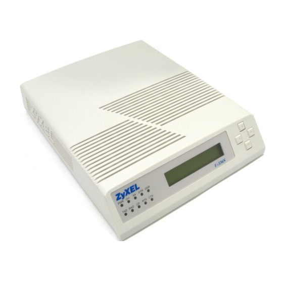
Front Panel The U-336S and the U-336SA models have 10 LED indicators, a 20 x 2 LCD display, and four key switches. The following figure shows the front panel of the U-336S. -
Page 22: Front Panel Leds
Figure 2-2 U-336SA Front Panel Front Panel LEDs PWR Power ON indicator, loghts up when your modem is turned Off-Hook indicator, lights up when your modem is in data mode or off-hook. It goes out when your modem is in talk mode or on-hook. -
Page 23: Front Panel Switches
Chapter LCD Panel Operation for details of menu key operations. Rear Panel Markings The U-336S/SA rear panels are shown below: Figure 2-3 U-336S Rear Panel Figure 2-4 U-336SA Rear Panel Explanations of the connectors and switch on the rear panel are given below. -
Page 24: Modem Connection
Pinouts. Modem Connection When you connect your U-336S modem to the power line, make sure you only use the power adapter that is supplied with this unit. Use of another adapter may not allow your modem to operate and could result in serious damage to the unit. - Page 25 Figure 2-5 U-336S Modem Connections For the U-336SA you don’t need an AC adapter. Use the supplied power cord to connect your modem to the AC power outlet. Figure 2-6 U-336SA Modem Connections If a leased line is not used, simply leave the connection open. There are no DIP switches or configuration settings that you need to worry about.
-
Page 26: Powering Up
conveniently stored in user selectable non-volatile memories and can be recalled as often as needed. Powering Up Once your modem’s power switch is turned ON, a series of diagnostic tests will be performed while a message is shown on the LCD panel. For a more detailed description of these diagnostic tests, please refer to Chapter 10 Diagnostics &... -
Page 27: Basic Modem Operation
Understanding AT Commands The U-336S/SA communicates asynchronously with computers using AT commands. AT commands are used to configure and control your modem. Commands are usually sent to the modem by way of communication software, but can also be entered manually by the user with the computer keyboard. -
Page 28: Using The Windows 95 Hyper Terminal Program
Using the Windows 95 Hyper Terminal Program In order to issue an AT command statement, you first need to run a communication program such as the Microsoft Windows “Hyper Terminal” program. This program provides a simple method to manually enter AT commands so you can do such things as “customize” the settings of your modem, or store commonly used phone numbers. -
Page 29: Dialing And Answering Techniques
You are now ready to start entering AT commands. In the terminal window, type: AT<Enter> Your modem responds This confirms that the modem and your computer are communicating correctly. To test the telephone line connection issue the manual answer command. Type: ATA<Enter>... -
Page 30: Auto-Answer And Hook Controls
Tone and Pulse Dialing: Dialing Through a PBX: IN THE DIAL STRING WILL CAUSE THE MODEM TO WAIT FOR A SECOND DIAL TONE BEFORE IT CONTINUES TO DIAL Pausing During Dialing: HE PAUSE TIME FOR EACH COMMA IS DEFINED BY SECONDS PER COMMA Dialing Without Waiting for Dial Tone: Originating a call using an Answer Tone:... -
Page 31: Quick Tips When Issuing At Commands
Quick Tips when issuing AT Commands The ENTER or RETURN key must be pressed to execute a command. Multiple AT commands can be combined into one line. For example, AT&D2 and AT&N0 can be combined into one line AT&D2&N0. Your modem processes commands from left to right. The AT command that appears to the right might over-write the command to the left if they are trying to accomplish tasks or set modes that cannot coexist. - Page 32 There are a few basic commands that do not require the “AT” command prefix. These are as follows: Command A> <any key> The U-336S/SA supports several groups of AT commands: AT Command Set/Type Basic AT (Hayes compatible) Basic AT$ (on line help) Extended AT& commands...
-
Page 33: Modem Result Codes
An OK result code means the AT command you sent was executed. If you receive an ERROR code, it means the command was invalid. The U-336S/SA also provides result codes that show: Whether or not a Dial Tone was detected when the modem originated a call. -
Page 34: Changing S Register Values
255. If n is set to 0, your modem will not answer incoming calls. Non-Volatile Memory The U-336S/SA has an amount of memory set aside for storing user information such as frequently used phone numbers and default command settings. The latter is particularly useful when using your modem to call a variety of different locations that require different settings. -
Page 35: Storing Phone Numbers
Storing Phone Numbers The AT command to store a phone number is in the format AT&Zs=n. The ‘s’ is a number from 0 to 49 that represents the location in memory that the phone number is to be stored, and the ‘n’ is the phone number itself. -
Page 36: Helpful Hints For Pc Computers
AT&Vn Views the settings in profile (n-1); n=0 to 5; n=0 views current settings. AT&Wn Stores the current settings in user profile ‘n’; n=0 to 3. ATZn Resets the current settings with the settings in profile ‘n’, n=0 to 4. Profiles 0 to 3: User profiles. -
Page 37: Default Modem Settings For Pc's
SMARTDRV execution in your AUTOEXEC batch file. Default Modem Settings for PC’s The U-336S/SA factory settings are configured for operation with PC type computers and communication software. In most cases, no additional settings will be required. The following are some of the... -
Page 38: Helpful Hints For Mac Computers
tasking systems. The serial port has a 32-byte transmission and a 32- byte receival FIFO to increase communication program efficiency. Helpful Hints for Mac Computers Special AT Command Settings for Mac For operation with Mac computers, you may use the factory default settings with one exception. -
Page 39: Helpful Hints For Unix-Based Computers
any program which runs on your Macintosh. At the same time it allows automatic fax receiving. This program includes powerful line manager software which makes sure fax software does not interfere with other programs using the serial ports. If the modem is turned off when you start your Macintosh with the line manager activated, the computer may seem to freeze for a few minutes. -
Page 40: Unix Software Tips
Unix Software Tips In order to use your ZyXEL modem from a terminal or an X-Windows application, you need a program such as Minicom or Seyon. If you wish to make use of your ZyXEL modem's special features, special gettys such as mgetty or vgetty are needed. These programs are available from several ftp-sites. - Page 41 Basic Modem Operation 27...
-
Page 42: Lcd Panel Operation
LCD Panel Operation This chapter explains how to place and receive calls using the U- 336S/SA front panel. An introduction to the panel operation of your modem is presented. Your modem comes with a menu driven 20 x 2 LCD display. All functions of the modem are displayed and selectable from this menu. -
Page 43: Panel Operation
computer/terminal or any key pad operation from the front panel. On the LCD screen, there are four on-screen buttons: The cursor is blinking above one of these on-screen buttons, a dark rectangle which may be moved using the keys next to the display. The modem also displays the current status and settings in the idle screen: Information Link Option... -
Page 44: Menu Tree
Down arrow key Menu Tree In command state, there are three main menu trees. The IDLE menu is the default, and can be accessed after the modem is powered on or reset. The second is the CONFIGURATION menu, which also includes a submenu. -
Page 45: Double Arrows On The Screen
Double Arrows on The Screen In some menu screens, you will see double left arrows (<<) or double right arrows (>>). This means there are more items on the left or right. Use the left or right arrow key to select them. If you can only see a double right arrow, this indicates that the current item is the first item of the menu. -
Page 46: Dial Memory
Dial Memory The first menu in the dialing directory is DIAL MEMORY. Pressing the ENTER key will display the following screen: z #00:12345 << >> SELECT MEMORY Equivalent AT Commands: AT&Z? ATDSn The first stored number shown on the menu is the default dial number which can be selected from the DEFAULT DIAL menu. -
Page 47: View And Store A Number
Equivalent AT Commands: AT&Z? View all stored phone numbers. AT&Zn=1234567 Store phone number in memory location n (n=0- 49). Up to 50 different numbers can be viewed and set. If you want to add a number to the memory, select an unused memory location and press ENTER. -
Page 48: Manual Dial
Equivalent AT Commands: ATD1234567 Manual Dial Use of a telephone set to make a call, in which case an answer tone comes back, is normally called Manual Dial. Once the other side answers, access O (Originate) by using the left or right arrow key so the blinking cursor settles on the O. -
Page 49: Repeat Last Dial
operation will reinitiate the modem handshaking and enable data communication. Equivalent AT Commands: Escape sequence code; causes a modem to return to command state. Enter the escape sequence while in data state and wait for the modem to respond. Go on-hook; disconnect the modem. Go on-line in Originate mode. -
Page 50: Dialing Messages
Dialing Messages Dialing will cause the following screen to be displayed on the LCD: DIALING ... 1234567 The dialed phone number will be displayed on the second line of the LCD screen. If the number exceeds 20 digits, only the first 20 digits/characters will be displayed. - Page 51 DISCONNECTING... 1234567 The modem will then return to the IDLE STATUS screen. If the first handshaking signal has been detected, the LCD screen will display: HANDSHAKING... 1234567 If a connection has been made, the LCD will display the actual connected status. These are V.34 data state screens: V.34b 33600 33600 <RIGHT>SNR= 41.5 CLC= H >>...
- Page 52 On-line Status Screen 1 Status Link Option Line Speed Error control Line Type Data Format Instant Transmission Throughput Instant Receiving Throughput On-line Status Screen 2 Status Signal to Noise Ratio Receiving Signal level Transmition Signal level Carrier lost Counts On-line Status Screen 3 Status Retrain Granted Retrain RequesTed...
- Page 53 Status Link Layer Status Block Size Blocks Retransmitted FCS (Frame Check Sum) Errors On-line Status Screen 5 Status Near End Echo Far End Echo Round Trip Delay Echo Frequency Offset On-line Status Screen 6 Status Phase Jitter Frequency Offset Echo delay On-line Status Screen 7 Status None Linear Encoder...
- Page 54 Status Transmitted Shaping Received Shaping Transmitted filter index Received filter index On-line Status Screen 9 Status Transmitted Carrirr Received Shaping Transmitted Baud rate Received Baud rate On-line Status Screen 10 Status Probing Result Pressing the left or right arrow key in any one of the ON-LINE STATUS screens will cause the LCD to scroll through the four screens.
-
Page 55: Panel Lock
However, viewing in the panel is not affected. This chapter introduces you to the use of the U-336S/SA for synchronous operation. The modem can be used as a synchronous modem when it is connected to a synchronous computer or terminal. It is of course necessary to make sure that the remote modem and system are also set to synchronous mode. -
Page 56: V.25Bis Command Set
of the non-FSK modes the modem is supplied with. Before synchronous transfers are started, some initial settings should be made. V.25bis Command Set To enable V.25bis commands use the AT*I1 command. For synchronous applications, the modem is permanently set in normal situations for use with one application. -
Page 57: Clock Options
Syntax Command with Parameters* LSN n; <number> Clock Options Synchronous data must be transmitted and received with a common timing clock. This timing clock is used to transmit data from the DTE to the modem which modulates the data according to this clock. The receiving modem recovers the clock and data from the carrier and sends the data to the receiving DTE along with the clock. -
Page 58: Rts Options
SLAVE RTS Options There are two RTS options. The choice depends on application and host/terminal requirements. In asynchronous mode RTS is used as a hardware flow control signal. IGNORED CTS TRACKS RTS Command State Options For synchronous data communication, there are two options you can choose from to define how the modem will operate in the command state. -
Page 59: Answering From Synchronous Mode
Once the modem is connected, the modem will enter synchronous operation. 2. Dial through the computer using V.25bis commands: Some communication software packages on synchronous computers can dial using V.25bis synchronous commands. In this case, set &M3 and *I1 and the modem will accept V.25bis commands and make a synchronous connection. -
Page 60: Leased Line Operation
2 -wire leased lines only. Connecting to a Leased Line The U-336S/SA default line is a dial-up type. The leased line must be connected to the jack labeled Line. Set your modem for leased-line operation by typing commands from the terminal. The leased-line phone jack pin assignments are shown in Chapter 12 Connector Pinouts. -
Page 61: Manual Connect
modem can be commanded to either answer the call immediately, or after a specified number of rings. In a leased-line connection, the communication circuit between two modems is always present. Dialing and waiting for rings does not occur in this situation. If these two modems want to establish a data link, one must be designated as the originator and the other as the answerer. -
Page 62: Terminating A Leased Line Connection
Terminating a Leased Line Connection A leased line can be terminated two ways: Going on-line manually. Turning the power OFF and ON. If you have set the leased line as the power-on default, the modem will try the leased line again. 48 Leased Line Operation... - Page 63 Leased Line Operation 49...
-
Page 64: Special Functions
Special Functions This chapter describes special features of the U-336S/SA, and offers instructions on how each is used. Security Functions Your modem provides a security function that prevents unauthorized users from making connections. Two types of security functions are provided. -
Page 65: User Passwords
With level 2 security, dial back the phone number corresponding to the dial-in password. The line simply disconnects if the password does not match. User Passwords Fifty user passwords may be defined. The corresponding 50 dial-back numbers are the modem’s 50 stored phone numbers. Any character (ASCII 0-127) can be used in the password, the maximum password length is 8 characters. - Page 66 ******** The command AT*Hn will modify the nth user password. You will be prompted to enter the supervisor password first and then be prompted to enter the nth user password. Levels of security: Command EFORE THE SECURITY TYPE OR LEVEL CAN BE CHANGED REQUIRES THE SUPERVISOR PASSWORD For type 2 security, the remote site will be prompted to enter the user password.
-
Page 67: Remote Configuration
Remote Configuration Remote configuration on the U-336S/SA is provided as a profile by profile batch mode. When on-line, the remote modem’s current configuration or one of its profiles can be read into one of the local modem’s user profiles. This profile is modified locally and the line can be disconnected during this time. -
Page 68: Caller Number Delivery (Caller Id)
The remote profile read and write commands - *Rab and *Wab - only work in the on-line condition. The connection speed and mode do not matter. The remote modem must be set to accept remote configuration by executing the AT*F1 command. The AT*F0 command will set the modem up to deny remote configuration requests. - Page 69 There are two kinds of caller information message formats sent by the phone company. One is the single message format which includes date, time, and caller ID The other is the multiple message format which also includes the caller name as registered with the phone company. The command ATS40.2=n is used to enable (n=1) or disable (n=0) the Caller ID detection function.
- Page 70 CALLER NUMBER: 7135551414 or CALLER NAME: Brent Harper RING In the multiple message format, if the caller’s number and name are available, the ring message will display both: RING TIME: MM-DD hh:mm CALLER NUMBER: <Caller_ID> CALLER NAME: <Caller_Name> RING Here is an example: RING TIME: 04-28 12:30 CALLER NUMBER: 7135551414...
-
Page 71: Distinctive Ring
Setting S48.0=1 will cause the modem to report CND information in its ASCII coded hexadecimal raw data format. The DTE software is responsible for explaining the data. LEASE REFER TO THE NWT-000030 FOR THE EXACT DATA FORMAT APPLIES TO THE DIFFERENT ALLER COUNTRY IS SUPPORTED BEFORE USING THE... - Page 72 part (cadence) of the ring. Your modem can distinguish up to four types of ring signals and can be commanded to answer or not answer any one of these four types of ring signals. Following is a list of these four types of ring signals.
-
Page 73: Extended Distinctive Ring (Edr)
Extended Distinctive Ring (EDR) Extended Distinctive Ring (EDR) is a special feature designed for single telephone line home use to receive fax or data calls without interfering with regular voice calls. When most users install a fax/modem at home, they won’t subscribe to an extra telephone line for occasional fax or data calls;... -
Page 74: Setting Up Edr
report RING to the software immediately. The software application can then issue commands to answer the call and receive the fax. If the remote caller is using a fax phone which does not send out a CNG tone and is waiting for a fax answer tone in order to press the START button, the caller can press a designated DTMF tone, which will activate the modem to report and subsequently be ordered to answer the fax call. -
Page 75: Edr Application Example
Bits Bin. EDR detection (either CNG or DTMF tones) will be disabled once detection occurs. However, a customer’s program might not answer because the setting of the software may require multiple rings to answer. S51 bits 0-1 control the number of rings that the modem will report once the CNG or DTMF tone is detected. - Page 76 2. Set S51.0=1 to enable EDR and report RING twice. The modem will not report a normal RING and ZFAX will not answer a call unless EDR RING is reported. 3. Set S51.4=1 to enable fax CNG tone detection. It is reported as RING.
- Page 77 Special Functions 63...
-
Page 78: Fax Operation
Fax Operation The U-336S/SA can be used as a fax machine. In the sections below, we will describe how the modem works as a fax machine, the ITU-T T.30 fax protocol, the Class 1,2, and 2.0 fax commands and ZyXEL extended fax AT commands. -
Page 79: Modem As Fax Machine
machine or such business, or entity, or individual. In order to program this information into the fax function of your modem, please refer to the documentation of the fax software you will be using. Modem as Fax Machine Modems can also be designed to include a fax transmitting and receiving function similar to a fax card. -
Page 80: Fax Command Sets
9600 bps and will automatically fall back to 7200, 4800, and 2400 bps if the line quality is poor. Fax Command sets The U-336S/SA supports four command sets for fax operation: Class 1 command set TIA PN-2388 Class 2 command set TIA 592 Class 2.0 command set... -
Page 81: Class 1 Command Set
Several revisions of the class 2 standard exist. Implementations conforming to different revisions may not work together. A formally approved version is the Class 2.0 command set, also called the TIA- 592 standard. Class 1 Command Set Command +FCLASS=n S57.4=0 ( DEFAULT NOT REPORT SOFTWARE PACKAGES MAY GET CONFUSED BY THIS RESPONSE... -
Page 82: Class 2 Command Set
Value Modulation Speed V.21 ch. 2 +FTH and +FRH support value 3 (V.21 ch. 2 / 300 bps) only. V.27ter V.27ter V.29 V.17 V.17 w/st V.29 V.17 V.17 w/st V.17 V.17 w/st V.17 V.17 w/st * w/st means with V.17 short training Class 2 Command Set The following Class 2 commands are supported and implemented per TIA PN2388 (8/20/90):... - Page 83 Command Value Description +FBADLIN= 0-255 Bad line threshold (number of <value> +FBOR=n +FBUF? +FCIG="string" +FCLASS=n +FCON +FCQ=n +FCR=n +FDCC=vr,br,wd ,ln,df,ec,bf,st vr=0 consecutive bad lines for a bad page parameter): Determine if Copy Quality OK on the T.30 flow chart . <value>=0 to 255; a value of 0 implies that error checking is disabled.
- Page 84 Command 70 Fax Operation Value Description vr=1 Vertical resolution: Fine; 196 lpi. br=0 Bit rate: 2400 bit/s; V.27ter. br=1 Bit rate: 4800 bit/s; V.27ter. br=2 Bit rate: 7200 bit/s; V.29 or V.17. br=3 Bit rate: 9600 bit/s; V.29 or V.17. br=4 Bit rate: 12000 bit/s;...
- Page 85 Command Value Description +FDCS=vr,br,wd ,ln,df,ec,bf,st +FDIS=vr,br,wd,l n,df,ec,bf,st +FDR +FDT=df,vr,wd, +FET=n +FLID="string" +FLO=n +FLPL=n +FMDL? Current session parameter; refer to +FDCC command. Current session negotiation parameter; refer to +FDCC command. Receive phase C data command; initiates document reception. Transmit phase C data command: release the DCE to proceed with negotiation.
- Page 86 Command +FMFR? +FMINSP=n +FPHCTO= <value> +FPTS=n +FREL=n +FREV? +FSPL=n 72 Fax Operation Value Description Request DCE manufacturer . Minimum phase C speed parameter: 2400 bps. 4800 bps. 7200 bps. 9600 bps. 12000 bps. 14400 bps. 0-255 DTE Phase C response time-out: Determine how long the DCE will wait for a command after reaching the end of data when transmitting in Phase C.
- Page 87 Command Value Description All other +F commands are not supported, but the modem will respond OK. In many cases this means "don't care." See PN 2388 for command details. Class 2 Command Responses Response Value Function and Description +FCFR +FCIG:"string" +FCON +FCSI:"string"...
-
Page 88: Class 2.0 Command Set
Response +FNSF:"HEX string" +FNSS:"HEX string" +FPOLL +FPTS:n +FTSI:"string" +FVOICE Class 2 Flow Control Flow control is necessary to match the DTE-DCE data rate to the line signaling rate while transmitting or receiving Group 3 (T.4) data. In Class 2 fax mode, both hardware (RTS/CTS) and software (XON/XOFF) flow control are enabled. - Page 89 Command Value Description mode for phase C data. +FBS? Buffer size parameter; read only. +FCC=vr,br,wd DCE capability parameter. Refer to ,ln,df,ec,bf,st +FDCC command in Class 2 for parameter settings. +FCLASS=n Service class selection. Refer to +FCLASS Class 1 command in previous section.
- Page 90 Command +FDT +FEA=n +FIE=n +FIP +FIS=vr,br,wd,l n,df,ec,bf,st +FKS +FLI="string" +FLO=n +FLP=n 76 Fax Operation Value Description document reception Transmit phase C data command: releases the DCE to proceed with negotiation Phase C received EOL alignment parameter Determine that T.4 EOL patterns are bit aligned (as received).
- Page 91 Command Value Description +FMI? Request DCE manufacturer identification. +FMM? Request DCE model identification. +FMR? Request DCE revision identification. +FMS=n Minimum phase C speed parameter. refer to +FMINSP Class 2 command in previos section for parameter settings. +FNR=rpr,tpr, Negotiation message reporting control idr, nsr parameters: rpr=0...
- Page 92 Command +FNS="string" +FPI="string" +FPR=n +FPS=n +FRQ=pgl,cbl +FSP=n 78 Fax Operation Value Description Non-standard byte string parameter. "string": string of hexadecimal coded octets. Local fax station ID string, for polling Rx. Serial port rate control parameter: Automatic DTE rate detection by the DCE.
- Page 93 Command Value Description Disable polling. Enable polling. Class 2.0 Command Responses Response Value +FCI:"CSI ID string" +FCO +FCS:vr,br,wd,ln ,df,ec,bf,st +FET:<ppm> ppm=0 Another page next, same document. ppm=1 Another document next. ppm=2 No more pages of documents. ppm=3 Another page next, same document, ppm=4 Another document next, procedure ppm=5 No more documents or pages, +FHS:<hsc>...
- Page 94 Response +FIS:vr,br,wd,ln, df,ec,bf,st +FNC: "NSC FIF string" +FNF: "NSF FIF string" +FNS: "NSS FIF string" +FPI: "CIG ID string" +FPO +FPS:ppr,lc,blc,c blc,lbc 80 Fax Operation Value Function and Description hsc= Receive phase B hang up codes. Refer 70-8F to TIA-592 for details. hsc= Receive phase C hang up codes.
-
Page 95: Extended Fax At Command Set
Response Value +FTC:vr,br,wd,ln ,df,ec,bf,st +FTI: "TSI ID string" +FVO Extended Fax AT Command Set Extended Fax AT Commands are unique to ZyXEL modems. The computer controls the modem through a set of extended fax AT commands and the modem responds with a set of status report result codes. - Page 96 Mode Setting Command Parameter Setting Command 82 Fax Operation Function Set the modem into V17G3 FAX mode same function as the extended AT command AT&N32. Set fax receiving mode. The connection parameters and received fax data are sent to DTE continuously following the connect message.
- Page 97 Command Function Set to two dimensional coding scheme. Set recording width: 1728 picture elements along a scan line length of 215 mm. Set recording width: 2048 picture elements along a scan line length of 255 mm. Set recording width: 2432 picture elements along a scan line length of 303 mm.
- Page 98 Status Report Result Codes When the U-336S/SA is in fax mode, each ATD or ATA command will make the modem try to establish a fax connection. Your modem will send a status report result code back to the DTE (computer).
-
Page 99: Flow Control
CONNECT and DISCONNECT status report result codes. The modem will always return the same status format as above. Flow Control In extended fax AT command mode, the U-336S/SA always uses hardware (CTS/RTS) flow control. The flow control signaling used sending a fax is: CTS is used by your modem for DTE flow control. -
Page 100: Fax Reception From A Bbs
DTE. Fax Reception from a BBS The U-336S/SA can automatically detect data and fax calls and allow BBS software to receive faxes on the same phone line. To allow your BBS to receive incoming faxes, make the following set-up changes in your BBS: 1. - Page 101 Add these commands to the init string: X7#B1+FCLASS=6 Change the connection message to: CONNECT 1200 CONNECT 1200 9600 1275 CONNECT FAX 19200 2400 CONNECT 2400 38400 Set external mail as: String Error Level 1 ZyXEL The following is a sample setting in the BINKLEY.CFG file for a Binkley system.
-
Page 102: At Command Set Summaries
AT Command Set Summaries Basic AT Command Set Command Options Function & Description A> <any key> All the Following Commands Require a “AT” Prefix: Command Options Function & Description B0 * 88 AT Command Set Summaries Re-execute the last command once. Re-execute the last command once or repeat the last call up to 9 times. - Page 103 Command Options Function & Description 0-9, #, * Digits for dialing Pulse dialing Ton dialing Pause for a time specified in S8. Remaining digits will be dialed as in- band DTMF. Return to command state after dialing Hook flash Wait for a 5 second silence before proceeding Reverse handshake (go on-line in Answer mode)
- Page 104 Command Options Function & Description n=0-7 M1 * n=0-7 Q0 * Modem returns result code Sr.b=n Sr.b? Sr=n 90 AT Command Set Summaries Display product information and ROM checksum Display modem link status report Display physical layer status Speaker volume control. The higher the value, the higher the volume Speaker control Speaker always OFF...
-
Page 105: Description Of Ati2 Output
Command Options Function & Description Ton dial Download firmware to the Flash EPROM by using Xmodem protocol Sets display type for Result Codes Display result code in numeric form. (See also S35.7 and the result code table of 'ATXn') V1 * Display result code in verbose form. - Page 106 Blocks Resent Max Block Size Link Duration FRN Requested FCS Errors Xmitter Underrun 0 Receiver Overrun Last Speed/Protocol 33600 Disconnect Reason Data Type Chars Octets Block Output Parameter Chars Sent Chars Received Octets Sent Octets Received Blocks Sent Blocks Received 92 AT Command Set Summaries 0 Max Outstanding 0 Retrains Requested...
- Page 107 Output Output Value Description Parameter Blocks Resent Number of blocks resent due to remote modem request. (If there were many blocks resent, you may have experienced line trouble or protocol incompatibility.) Max Outstanding Maximum blocks received without acknowledgment by remote modem. Max Block Size Maximum octets contain in a block Retrains...
-
Page 108: Extended At& Command Set
Output Parameter Extended AT& Command Set Command Options Function & Description &Bn &B0 &B1 * DTE/DCE rate fixed at DTE setting &Cn &C0 &C1 * CD tracks presence of carrier (See &Dn &D0 &D1 &D2 * 108.2, Data Terminal Ready, DTR 94 AT Command Set Summaries Output Value Description Break Time-out... - Page 109 Command Options Function & Description &D3 Same as &D2 but DTR OFF causes the modem to hang up and reset from profile 0. &F Load factory settings to RAM as active configuration. &Gn Guard tone options &G0 * No guard tone (within USA, Canada).
- Page 110 Command Options Function & Description &M0 * Asynchronous mode with data &M1 &M2 &M3 &Nn &N0 * Multi-Auto, auto negotiate highest &N1 &N2 &N3 &N4 &N5 &N6 &N7 &N8 96 AT Command Set Summaries selection buffering Asynchronous command, synchronous data Direct asynchronous mode, no data buffering Synchronous mode...
- Page 111 Command Options Function & Description leased lines only) &N9 V.27bis 4800 (models with 4-wire leased lines only) &N10 V.27bis 2400 (models with 4-wire leased lines only) &N11 V.26bis 2400 (models with 4-wire leased lines only) &N12 V.23 1200/75 (See also S48b3, S52b7) &N13 V.23 600/75 (See also S52b7)
- Page 112 Command Options Function & Description &N44 &N45 &N46 &N60 &N61 &N62 &N63 &N64 &N65 &N66 &N67 &N68 &N69 &N70 &N71 &N72 &N73 &Pn &P0 * make / break, 39% / 61% &P1 &Rn &R0 &R1 * Ignore RTS, assumes RTS always &Sn &S0 * DSR overridden, DSR always ON.
- Page 113 Command Options Function & Description TSS). (See also S41.5, S44.4) &Tn Modem testing. &T0 Terminate test in progress. &T1 Initiate Analog Loop-back (ALB) test. &T3 Initiate Local Digital Loop-back (LDL) test &T4 Grant Remote Digital Loop-back request from remote modem &T5 Deny Remote Digital Loop-back request from remote modem...
-
Page 114: Extended At* Command Set
Command Options Function & Description &X1 &X2 &Yn &Y0 &Y1 * Nondestructive, expedited. &Y2 &Z? &Zn=s n=0-49 Write phone number/s to NVRAM at Extended AT* Command Set Command Options Function & Description *C0 * n=0-49 Set default dial pointer at telephone 100 AT Command Set Summaries Terminal provides synchronous transmit clock signal (External clock... - Page 115 Command Options Function & Description directory location n. *D0 * (See also S35.4 and S38.0) Modem error control negotiation. *E0 * if error control negotiation fails, keep the non-error control connection. If error control negotiation fails, disconnect the call (hang-up). Remote configuration enable *F0 * Deny remote configuration Accept remote configuration (Remote...
- Page 116 Command Options Function & Description *I0 * n=0-15 *P9 * *Q2 * Adaptive rate, automatic fall-back or *Rab a=0-3 b=0-3 *S0 * Secondary channel disabled 102 AT Command Set Summaries Command set selection AT command set V.25bis command set Dumb mode Leased line auto-handshake mode selection Set to Originate mode...
- Page 117 Command Options Function & Description View the Password table *Wab Write local configuration profile “a” to remote user profile “b” and reset remote modem from profile “b” a=0-3 Local user profile number “a” Local active configuration Local factory default configuration b=0-3 Remote user profile number “b”...
- Page 118 104 AT Command Set Summaries...
-
Page 119: Status Registers & Result Codes
Status Registers & Result Codes S-Register Descriptions In most bit-mapped S-registers, the default bit value is 0. Non-0 default values are followed by an asterisk. In some cases, default values are shown in the reference column preceded by +. Some bits are reserved for factory use and should not be changed. -
Page 120: Extended S-Registers "Atsn=X
Command Function & Description register also sets the time-out interval for the “W” dial modifier to wait for the dial tone. (See also S41b4) Set duration, in number of seconds modem waits for a carrier Set duration, in seconds, for pause (,) option in Dial command and pause between command re-executions for Repeat (>) command Set duration, in tenths of a second of remote... - Page 121 Command bit dec hex Function and description 3,2 0 5,4 0 7,6 0 128 80 192 C0 S15= bit dec hex Bit-mapped register 0,1 0 2 * No parity 0 * 1 stop bit 4,3 0 0 * 10 bit character length 7-5 0 Grant Remote Digital Loop-back test request...
- Page 122 Command bit dec hex Function and description S16= S17= bit dec hex Bit-mapped register 4-1 0-30 0-1E Set leased line transmit power 7,6 0 108 Status Registers & Result Codes power on Profile 2 as active settings after power on Profile 3 as active settings after power on 128 80 * Factory default as active settings...
- Page 123 Command bit dec hex Function and description S18= dec hex Force modem to fix baud rate 0 * 0 1-46 1-2E Enable baud rate to be fixed S19= dec hex Modem connection mode, same +000/ 0-73 0-49 setting value as 'AT&Nn' S20= dec hex DTE speed (bps).
- Page 124 Command bit dec hex Function and description Note: Only the speeds up to S20=15 are supported by auto speed detection. S21= bit dec hex Bit mapped register 1-2 0 110 Status Registers & Result Codes 153600 bps 102400 bps 61440 bps 51200 bps 624000 bps 124800 bps...
- Page 125 Command bit dec hex Function and description 6-7 0 128 80 192 C0 S23= bit dec hex Bit mapped register 3-5 0 CD tracks presence of data carrier (see also S38.3) CTS Follows RTS in synchronous mode. Response delay set in S26 Ignore RTS (CTS always ON) in synchronous mode.
- Page 126 Command bit dec hex Function and description S24= bit dec hex Bit mapped register 2-0 0-7 0-7 Ring Volume control, increment 6-4 16- S25= S26= 112 Status Registers & Result Codes ATX3 ATX4 ATX5, error control result code enabled (Default) ATX6, error control result code enabled ATX7, error control result code...
- Page 127 Command bit dec hex Function and description S27= bit dec hex Bit mapped register 3-5 0 128 80 192 C0 S28= bit dec hex Bit mapped register command) Modem error control No error control MNP4 + MNP3 (see also S41.0) MNP4 + MNP5 (see also S38.5, S41.0) V.42+MNP4...
- Page 128 Command bit dec hex Function and description 2-3 0 4-5 0 S29= S31= S32= S35= bit dec hex Bit mapped register 114 Status Registers & Result Codes Multiple phone/modem line, RJ12/RJ13 phone jack Panel key is normal (default) Panel key is locked Destructive, expedited break Non-destructive, expedited break (default)
- Page 129 Command bit dec hex Function and description 128 80 S36= bit dec hex Bit-mapped register Use CELL 4800T trells coded 4800 for V.32 4800 (available with cellular mode only) Disable aborting from terminal during modem handshaking V.26 alternative A. (see also ‘&N11’) Add 12 dBm attenuation to the leased line transmission power...
- Page 130 Command bit dec hex Function and description S37= bit dec hex Bit-mapped register for remote 3-0 0-5 0-5 Remote profile number 7-4 0-80 0-50 Local profile number S38= bit dec hex Bit mapped register 116 Status Registers & Result Codes Grant remote request for configuration Write from local profile a to...
- Page 131 Command bit dec hex Function and description S39= bit dec hex Bit mapped register S40= bit dec hex Bit mapped register number DCD ON/OFF sequence follows UNIX standard, DCD high before connect message is sent, DCD off after last DCE response is sent Auto-mode fax receiving disabled...
- Page 132 Command bit dec hex Function and description S41= bit dec hex Bit mapped register S42= bit dec hex Bit mapped register 118 Status Registers & Result Codes Enables type 4 ring detection Special MNP compatibility (see also S27.0, S38.5) Disable retrain abort, up to 5 min.
- Page 133 Command bit dec hex Function and description S43= bit dec hex Bit mapped register 128 80 S44= bit dec hex Bit mapped register 0.5 seconds at carrier loss Disable ZyXEL 16800 in Multi- Auto mode Disable ZyXEL 19200 in Multi- Auto mode Disable cellular mode automatic transmit power adjustment (see...
- Page 134 Command bit dec hex Function and description S45= S46= S48= bit dec hex Bit-mapped register 120 Status Registers & Result Codes speed fixed at 9600 if link speed is 7200, DTE speed follows link speed. When selected with &B1, DTE speed fixed at current rate when an ARQ connection is made, when a non-ARQ connection is made, DTE speed...
- Page 135 Command bit dec hex Function and description S49= bit dec hex Bit-mapped register 3-0 0-15 0-F Set cellular mode transmit power 128 80 S50= dec hex Inactively timer, in 10 second 0-FF The modem counts when there is times out. Enable data calling tone (CNG) sending Reverse the V.23 channel speed.
- Page 136 Command bit dec hex Function and description S51= bit dec hex Bit-mapped register 1-0 0 3-2 0 5-4 0 7-6 0 S52= bit dec hex Bit-mapped register 4-3 0-24 0-18 Receive level adjustment 122 Status Registers & Result Codes reaches the preset value. Set value ‘0’...
- Page 137 Command bit dec hex Function and description 128 80 S56= dec hex 0-FF Hook flash detect time, in units S57= bit dec hex Bit-mapped register S62= bit dec hex Bit mapped register -43 dBm (Default) -33 dBm -26 dBm -26 dBm Select ‘Mark’...
-
Page 138: Result Code Options
S-register bit number, 'b', used in 'ATSr.b=n' and 'ATSr.b=?' Decimal value, 'x', used in 'ATSn=x' Equivalent Hexadecimal value. +nnn Factory default when listed in 'Reference' column. Note: 'AT' is omitted when an AT command is referred to in the 'Reference' column.. Result Code Options "ATXn"... - Page 139 ATV0 ATV1 CONNECT 12000 CONNECT 14400 CONNECT 16800 CONNECT 38400 CONNECT 57600 CONNECT 76800 CONNECT 115200 CONNECT 230400 CONNECT 460800 CONNECT 921600 CONNECT 307200 CONNECT 153600 CONNECT 102400 CONNECT 61440 CONNECT 51200 CONNECT 624000 CONNECT 124800 CONNECT 62400 CONNECT 41600 CONNECT 31200 CONNECT 24960 CONNECT 20800...
-
Page 140: Result Code Field Descriptions
** When more than one type of Distinctive Ring is turned on (S40b3-6) ‘RING n’ will be reported, n=Ring Type # (1-4) Result Code Chart Symbol Reference: Supported Reports the DTE Speed as: <cr><lf>CONNECT DTE_Speed<cr><lf> CONNECT DTE_Speed/Protocol DCE_Speed/Error_Control † Example: CONNECT 38400/V.32bis 14400/V.42bis <cr><lf>CONNECT DCE_Speed[/Error_Code]<cr><lf>... -
Page 141: Connect Strings For Error Corrected Connections
Connect Strings for Error Corrected Connections To enable the following numerical (ATV0) and verbose (ATV1) result codes when an error corrected connection is made, set S35 bit 7 to 1.(ATS35.7=1) Numerical V0 Verbose V1 CONNECT CONNECT 1200 CONNECT 2400 CONNECT 4800 CONNECT 7200... -
Page 142: Diagnostics & Troubleshooting
Diagnostics & Troubleshooting Diagnostics The U-336S/SA is equipped with several diagnostic capabilities: Power-on Self Test. Analog Loop-back Test. Analog Loop-back with Self-Test. Local Digital Loop-back Test. Remote Digital Loop-back Test. Remote Digital Loop-back with Self-Test. The diagnostic tests listed above apply to several modes of operation: asynchronous or synchronous, error controlled or non-error controlled, data compression enabled or disabled data mode. -
Page 143: Resetting The Modem
code checksum, DSP RAM memory, EEPROM, digital circuits, and the analog circuit calibrations. Results of the power-on self-test displayed on your terminal: 0 SYSTEM TESTING 1 ROM TEST FIAL... 2 RAM TEST FAIL... 3 LOADING DEFAULTS. 4 DSP RAM FIAL... 5 DSP RAM FIAL... -
Page 144: Loopback Tests
temporary power-on reset problem and will not affect modem operation. Loopback Tests The Analog Loopback Test, Local Digital Loopback Test, Remote Digital Loopback Test can all be initiated with AT commands from the terminal. Use the AT&T0 command to terminate the test. Analog Loopback (AT&T1) This test can check almost every part of the modem and the RS-232 cable except the telephone line outgoing interface. - Page 145 Local Digital Loopback Test (AT&T3) This test will loopback the digital form data demodulated from the receiver to the input of the transmitter. During testing, all data received from the remote modem will be returned to the remote modem. This test is applicable when the remote modem does not provide V.54 Remote Digital Loopback capability.
-
Page 146: Indicator Lights
Indicator Lights Retransmission Indicator In the error control mode, an error occurring in the link will cause the data to be re-transmitted. At the same time, the AA LED will flash. This also indicates the quality of the line. Dialing Indicator The V34 LED will flash on and off for 1/2 second each to indicate that the modem is dialing. - Page 147 measuring the distance between the demodulated signal point and the ideal signal point. For V.32/V.32bis, the modem-measured S/N ratio is generally about 2 dB higher than what is actually on the line because the modem rejects some of the out-of-band noise. For V.22/22bis, the difference can be as high as 8 dB because the modem only uses part of the 3 KHz bandwidth and rejects more than half of the voice band noise.
- Page 148 Retrain Granted (RTG) The count of the granting of the remote modem's retrain requests. Each request is an indicator of bad receiving conditions. Retrain Requested (RTR) The count of the local modem's requests for the remote modem to retrain when the signal quality is poor. Round Trip Echo Delay (RTD) Measured in T (1/2400 sec.).
-
Page 149: Trouble Shooting
Trouble Shooting Your modem is designed to provide years of ultra high speed satisfaction. In the unlikely event you encounter problems using your modem, the tips in this section will help you to identify and resolve them. Most modem problems are a result of incorrect cabling or settings within your communications or fax software. -
Page 150: Command Echo Problems
3. You may have typed the commands when your modem was in data state instead of the command state. To switch from data state to command state, type the escape sequence code +++. To return to the data state, type ATO and press Enter. Problem You typed an AT command, but did not receive an OK or 0 result code. -
Page 151: Answer Problems
Solutions 1. Make sure the DTR LED is ON. If it is OFF, make sure your communications software is using the same COM port as your modem. 2. Neither your modem nor your communications software is configured to echo characters. Use the E1 command to enable modem echo, or turn on your software program’s Echo (or duplex) feature. -
Page 152: Dialing Problems
3. Check that the DTR LED is ON, and that the AA LED flickers with each incoming ring. If the LEDs do not respond in this way, refer to your ZyXEL Modem Reference Manual. 4. Set &D and auto answer, if your modem is not connected to RS232 or DTR is not ready. -
Page 153: Connection Problems
Solutions 1. Your modem and communications software may be configured for different flow control methods. Be sure your modem and software are both using hardware (RTS/CTS) flow control or software (XON/XOFF) flow control. 2. To verify that your modem and communications software are using the same flow control method, type AT&T8 and press the Enter key with your modem in the command state. -
Page 154: Upgrading Your Modem
Upgrading Your Modem Upgrading by Flash EPROM 1. Obtain the new firmware by downloading from the ZyXEL BBS, WWW or FTP site. See Contacting ZyXEL on page vi for the FTP address. 2. Turn on your computer. 3. Turn on your modem. 4. -
Page 155: Kernel Recovery Mode
Kernel Recovery Mode Your modem is equipped with ZyXEL’s exclusive Kernel Recovery Mode. This unique feature enables quick recovery from failed flash uploads. With other modems, a failed flash upload usually results in the user having to return the modem to the factory for repair. In the unlikely event that your modem fails to respond to AT commands after upgrading the flash EPROM: 1. -
Page 156: Connector Pinouts
Connector Pinouts Phone Jack Pinouts The ZyXEL U-336S/SA modem features two RJ-11 phone jacks, one for 2-wire dial-up and 2-wire leased line connection (LINE) and one for an optional connection to a telephone set (PHONE). The signals on these pins are:... - Page 157 Signal ITU-TSS Signal Signal Name Name 108/2 108/1 Pin/Signal Direction Description DTE-DCE (CTS). Data Set Ready (DSR). Signal Ground (GND). Data Carrier Detected (DCD). Transmit Clock Signal (source: DCE). Synchronous Receive Clock. Local Analog Loopback Test. Data Terminal Ready (DTR). Connect DCE to line Remote Digital Loop Test.
-
Page 158: Macintosh Serial Port Pinouts
Macintosh Serial Port Pinouts The following table shows the wiring of a modem Macintosh hardware handshaking cable: Modem Din 8 DB 25 4 & 20 144 Connector Pinouts Description DTR to RTS and DTR, Hardware Handshaking Out CTS to CTS, Hardware Handshaking In TX- to TXD, Data sent GND, Ground RX- to RXD, Data received... - Page 159 Connector Pinouts 145...
-
Page 160: Index
Index AT commands, 4, 13, 14, 15, 16, 18, 20, 27, 43, 50, 63, 80, 84, 127, 131, 132, 138 Combining, 16 Quick Tips, 16 ATI2 Output, 90 Auto-Answer, 8, 16, 34, 44 Caller ID, 3, 53, 54, 56, 60, 101 Command Characters, 15, 23 Command State Options, 43 Contacting ZyXEL, vi... - Page 161 Panel Lock, 40 PC Serial Port Pinouts, 139 Phone Jack Pinouts, 139 Phone Numbers, 20, 21 Dialing stored, 21 Storage, 20 power adapter, 10 Power Level Setting, 45 Powering Up, 12 Rear Panel Markings, 9 Redial operation, 34 Remote Configuration, 52 Required Equipment, 1 Resetting The Modem, 126 Result Code Options...