Nortel BCM50 Installation And Maintenance Manual
Hide thumbs
Also See for BCM50:
- Configuration manual (568 pages) ,
- Installation and maintenance manual (335 pages) ,
- Administration manual (191 pages)

Related Manuals for Nortel BCM50


Summary of Contents for Nortel BCM50
- Page 1 Return to Menu Part No. N0027152 January 14, 2005 BCM50 Installation and Maintenance Guide...
- Page 2 N0027152...
-
Page 3: Table Of Contents
BCM50 overview........ - Page 4 Chapter 2 Introduction to the BCM50 hardware ......45 BCM50 Main Units ........... . 45 BCM50 Main Unit .
- Page 5 Install the BCM50 unit in an equipment rack ....... .
- Page 6 Install the BCM50 unit on a table or shelf ......106...
- Page 7 BCM50 Main Unit (no integrated router) ........
- Page 8 Test the BCM50 Expansion Unit ........178 Troubleshoot the BCM50 Expansion Unit ....... . . 178...
- Page 9 Replace the BCM50 Main Unit........185...
- Page 10 Return the BCM50 system to operation ........
- Page 11 Index ............263 BCM50 Installation and Maintenance Guide...
- Page 12 Contents BCM50 Installation and Maintenance Guide...
-
Page 13: Figures
BCM50 wiring field card connectors ........53... - Page 14 Telephony connector on a BCM50 ........223...
- Page 15 ASM RJ-21 connector ......... . . 247 BCM50 Installation and Maintenance Guide...
- Page 16 Figures BCM50 Installation and Maintenance Guide...
-
Page 17: Tables
BCM50 field-replaceable units ........ - Page 18 CallPilot feature default anomalies ........261 BCM50 Installation and Maintenance Guide...
-
Page 19: Preface
BCM50 system. This guide assumes the following: • There is an existing plan outlining the telephony and data requirements for your BCM50 system. • That all operators have a working knowledge of the Windows operating system and graphical user interfaces. -
Page 20: Symbols Used In This Guide
Warning: Alerts you to ground yourself with an antistatic grounding strap before performing the maintenance procedure. Warning: Alerts you to remove the BCM50 Main Unit and BCM50 Expansion Unit power cords from the ac outlet before performing any maintenance procedure. -
Page 21: Text Conventions
Indicates that you press the button with the coordinating icon on HOLD whichever set you are using. RELEASE Related publications In addition to the BCM50 Installation and Maintenance Guide (N027152), the BCM50 documentation suite contains the following documents: • Management User Guide •... -
Page 22: Acronyms Used In This Guide
• Interactive Voice Response Installation and Configuration Guide (IVR) From the BCM50 Documentation CD, you can also access a number of telephone and accessory quick reference cards. If you operate a multi-site BCM network, you can use the Network Configuration Manager to provide centralized configuration and management operations. - Page 23 Acronyms used in this guide Backup and Restore Utility Centralized Auto Attendant Equal Access Identifier Code (carrier code) Central Answering Position (T7316E+KIM or M7324+CAP modules) Coordinated Dialing Plan CHAP Challenge-Handshake Authentication Protocol Carrier Identification Code Committed Information Rate CLID Calling Line Identification COPS Common Open Policy Service Class of Service...
- Page 24 Acronyms used in this guide Data Terminal Equipment Digital Trunk Module DTMF Dual Tone Multifrequency. Egress Border Node Expedited Forwarding eKIM enhanced Key Indicator Module Edge Node End Station Encapsulated Security Payload FQDN Fully Qualified Domain Name File Transfer Protocol GATM Global Analog Trunk Module HDLC...
- Page 25 Acronyms used in this guide Key Indicator Module Local Area Network Liquid Crystal Display Link Control Protocol LAN Manager Link Quality Rate Media Access Control Media Access Unit MCDN Meridian Client Defined Network (PRI SL-1) Message Digest algorithm MLPPP Multi-Link Point-to-Point Protocol MPPC Microsoft Point to Point Compression Message Waiting Indicator...
- Page 26 Acronyms used in this guide Permanent Virtual Circuit Quality of Service QOTD Quote of the day server QSIG Q reference point signalling Remote access service Routing Information Protocol Receive Loudness Rating Remote Procedure Call Realtime Transport Protocol Service Advertising Protocol SAPS Station Auxiliary Power Supply Secure Hash Algorithm...
- Page 27 Acronyms used in this guide VoIP Voice over IP Virtual Private Networks Wide Area Network Weighted Fair Queuing WINS Windows Internet Name Service Preface...
- Page 28 Acronyms used in this guide Preface...
-
Page 29: How To Get Help
How to get help If you do not see an appropriate number in this list, go to: www.Nortelnetworks.com/support. USA and Canada Authorized Distributors - ITAS Technical Support Telephone: 1-800-4NORTEL (1-800-466-7835) If you already have a PIN Code, you can enter Express Routing Code (ERC) 196#. If you do not yet have a PIN Code, or for general questions and first line support, you can enter ERC 338#. - Page 30 How to get help In-country toll free numbers Australia 1800NORTEL (1800-667-835) China 010-6510-7770 India 011-5154-2210 Indonesia 0018-036-1004 Japan 0120-332-533 Malaysia 1800-805-380 New Zealand 0800-449-716 Philippines 1800-1611-0063 Singapore 800-616-2004 South Korea 0079-8611-2001 Taiwan 0800-810-500 Thailand 001-800-611-3007 How to get help...
-
Page 31: Regulatory Information
Danger: Risk of shock. Read and follow installation instructions carefully. Ensure the BCM50 modules are unplugged from the power socket and that any telephone or network cables are unplugged before opening the BCM50 modules. If installation of additional hardware and /or servicing is required, disconnect all telephone cable connections prior to unplugging the BCM50 modules. -
Page 32: Enhanced 911 Configuration
Telecommunication registration BCM50 equipment meets all applicable requirements of both Industry Canada CS-03 and US Federal Communications Commission (FCC) Part 68 and has been registered under files Industry Canada 332D-5980A and FCC US: AB6KF15B20705 (key system), US: AB6MF15B20706 (hybrid system), and US: AB6PF15B23740 (PBX system). -
Page 33: Network Connection
BCM50 equipment meets all FCC Part 15, Class A radiated and conducted emissions requirements. BCM50 does not exceed the Class A limits for radiated and conducted emissions from digital apparatus as set out in the Radio Interference Regulations of Industry Canada. -
Page 34: Use Of A Music Source
Music On Hold or Background Music features of this telecommunication system. Nortel Networks hereby disclaims any liability arising out of the failure to obtain such a license. Rights of the telecommunications company If the BCM50 system or adjunct systems is causing harm to the telephone network, the telecommunications company may discontinue service temporarily. -
Page 35: Notice
Do not attempt to repair this equipment. If you experience trouble, write for warranty and repair information: Nortel Networks 30 Norelco Drive, Weston, Ontario M9L 2X6 Canada US regulations - please read carefully... - Page 36 • Do not attempt to repair this equipment. If you experience trouble, write for warranty and repair information: Nortel Networks 640 Massman Drive, Nashville, TN, 37210, USA Ringer equivalence number The FCC Registration label (on bottom of phone), includes a Ringer Equivalence Number (REN), which is used to determine the number of devices you may connect to your phone line.
-
Page 37: Emi/Emc (Fcc Part 15)
North American regulatory information EMI/EMC (FCC Part 15) Note: This equipment has been tested and found to comply with the limits for a Class A digital device, pursuant to Part 15 of the FCC Rules. These limits are designed to provide reasonable protection against harmful interference in a residential installation. - Page 38 North American regulatory information This symbol on the product is used to identify the following important information: Use only with a CSA or UL certified CLASS 2 level C power supply, as specified in the user guide. When using your telephone equipment, basic safety precautions should always be followed to reduce risk of fire, electric shock and injury to persons, including the following: Read and understand all instructions.
-
Page 39: International Regulatory Information
This is a class A product. In a domestic environment this product may cause radio interference in which case the user may be required to take adequate measures. Hereby, Nortel Networks declares that BCM50 Model No. NT7B10xxxx, is in compliance with the essential requirements and other relevant provisions of Directive 1999/5/EC. -
Page 40: Additional Safety Information
International regulatory information Warning: Risk of shock. Ensure the BCM50 is unplugged from the power socket and that any telephone or network cables are unplugged before opening the BCM50. Read and follow installation instructions carefully Warning: Only qualified persons should service the system. - Page 41 International regulatory information • auxiliary ringer (AUX) • paging system relay (PAGE) • LAN interface The following interfaces are classified as Telecommunication Network Voltage (TNV) circuits, and shall NOT be connected to exposed plant: • ATA II Regulatory information...
- Page 42 International regulatory information Regulatory information...
-
Page 43: Bcm50 Overview
The BCM50 integrates voice and data capabilities, IP Telephony gateway functions, and data-routing features into a single telephony system. The BCM50 is a compact system that allows you to create and provide telephony applications for use in a business environment. -
Page 44: Bcm50 Features
Small system wallmount bracket: A bracket designed for mounting the BCM50 Main Unit or BCM50 Expansion Unit to a wall. An optional wiring field card (WFC) is available with the wallmount bracket, which provides RJ-45 connectors for all BCM50 Main Unit trunk and station interfaces. -
Page 45: Introduction To The Bcm50 Hardware
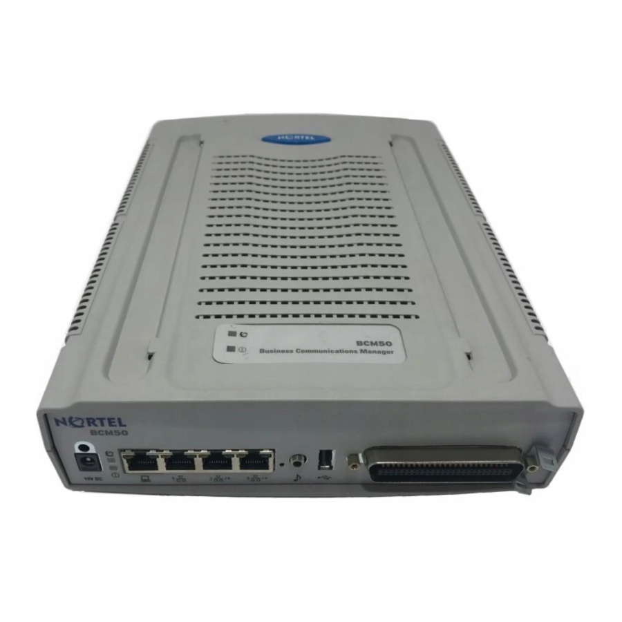
“Telephones and adapters” on page 67 • “Uninterruptable power supply” on page 69 BCM50 Main Units The main hardware component in the BCM50 system is the Main Unit. The three types of Main Units are: • “BCM50 Main Unit” on page 45 •... - Page 46 • Expansion/LAN ports (ports 2 and 3) Two RJ-45 jacks used to connect the BCM50 Expansion Unit to the BCM50 Main Unit. The expansion ports can also provide connections to the ethernet switch internal to the BCM50 Main Unit. If the BCM50 system does not have BCM50 Expansion Units connected to these ports, you can use them to connect additional devices to the LAN.
-
Page 47: Bcm50E Main Unit
Figure 2 on page 48): • Power connector A barrel connector jack used to connect the BCM50 power supply to the BCM50e Main Unit. • OA&M port (port 0) An RJ-45 jack used to connect a computer running administration software, such as Element Manager, to the BCM50e Main Unit. -
Page 48: Bcm50A Main Unit
(UPS) to the BCM50e Main Unit. The data interface for the UPS allows the BCM50 to monitor and control the UPS functions. To connect both a USB storage device and UPS data interface, a USB hub is required. - Page 49 (UPS) to the BCM50a Main Unit. The data interface for the UPS allows the BCM50 to monitor and control the UPS functions. To connect both a USB storage device and UPS data interface, a USB hub is required.
-
Page 50: Bcm50 Expansion Unit
(port 2, port 3) BCM50 Expansion Unit If you want to increase the number of devices that you can connect to the BCM50 system, you can add up to two BCM50 Expansion Units. The BCM50 Expansion Unit provides a single bay into which you can install a media bay module (MBM). -
Page 51: Bcm50 Hardware
BCM50 hardware To connect an MBM to the BCM50 system, you must install the MBM in the BCM50 Expansion Unit, then connect the BCM50 Expansion Unit to the BCM50 Main Unit. See “Install a BCM50 Expansion Unit” on page 109 for more information on installing a BCM50 Expansion Unit. -
Page 52: Rackmount Shelf
These tabs prevent the unit from sliding around or falling off the shelf. If the BCM50 system includes additional units, another unit can be clipped to a second set of tabs on the rackmount shelf. Any additional units can be clipped to tabs on the top of the other units... -
Page 53: Bcm50 Wiring Field Card
Figure 7 Rackmount shelf installed in equipment rack BCM50 wiring field card The BCM50 wiring field card (WFC) simplifies the connections of lines and extensions to the BCM50 Main Unit. The BCM50 WFC installs into the cable management tray of the wallmount bracket and connects to the telephony connector through a 50-pin header. -
Page 54: Bcm50 Patch Panel
BCM50 patch panel The BCM50 patch panel simplifies the connections of lines and extensions to the BCM50 Main Unit. The BCM50 patch panel installs into the rackmount shelf in a standard equipment rack and connects to the telephony connector (see... -
Page 55: Bcm50 Components
The power supply adapter cord is for international (non-North American) BCM50 users. It connects to the BCM50 power supply on one end and to the (C-14) BCM50 power bar on the other end. You require one power supply adapter cord for each power supply you want to connect to the power bar. -
Page 56: Hard Disk
The BCM50e has a router card that uses an ethernet interface to connect to a WAN edge device (for example, an external ADSL modem or cable modem). The BCM50a has a router card that uses an ADSL interface to connect the BCM50 system to the Internet Service Provider. -
Page 57: Telephony Connector
When you use the page output to connect an external paging amplifier, you also use the page relay. The page relay connects to a floating relay contact pair. The BCM50 uses the page relay to control the external paging amplifier. -
Page 58: Bcm50 Field-Replaceable Units
North American telephony interface standards only. If your BCM50 system is in a country that uses a different telephony standard, you must use media bay modules for your analog trunks and media bay modules or ATAs for your analog telephony devices. -
Page 59: Telephony Components
• Telephones and adapters: Business telephones and adapters connect to the telephony connector on the Main Unit and to the MBMs installed in the BCM50 Expansion Units. The BCM50 supports Business Series Terminal sets, IP Telephony-based Nortel sets, and analog telephony devices. -
Page 60: Media Bay Modules
The back of the media bay modules (MBM) have a single connector that provides signaling channels, media channels, and power to the MBM. This connector plugs into the MBM backplane in the BCM50 Expansion Unit. Some MBMs also have a cooling fan that runs off the MBM power source. -
Page 61: Digital Trunk Media Bay Module
MCDN over ISDN. • On North American BCM50 systems, the DTM connects to a T1 or PRI line. With a T1 line, you can add a maximum of 24 digital telephone lines. With a PRI line, you can add a maximum of 23 digital telephone lines. -
Page 62: Basic Rate Interface Media Bay Module
Each BRI ISDN loop you connect adds two telephone lines to the BCM50 system. Therefore, each BRIM adds a maximum of eight lines to the BCM50 system through the four RJ-48C jacks on the faceplate. The LEDs beside each RJ-48C jack are on when the ISDN line is active. -
Page 63: Digital Drop And Insert Multiplexor
Digital drop and insert multiplexor (North American systems only) The digital drop and insert multiplexor (DDIM) module enables a BCM50 system to share its connection to a universal T1 network with the data network to provide a combination of voice and... -
Page 64: Digital Station Media Bay Module
This module also allows you to download new firmware. Digital station media bay module The digital station media bay modules (DSM) support digital telephones on the BCM50 system. This section describes the DSM16+ and DSM32+ media bay modules (see Figure 18). -
Page 65: 4X16 Media Bay Module
Firmware downloading capability: allows the core to upgrade the GASM8 firmware at customer sites • Enhanced ringing capability • Supports off-premises extensions (OPX) Both the ASM8 and the GASM8 have one RJ-21 connector on the faceplate. Figure 20 on page 66 shows the ASM8. Introduction to the BCM50 hardware... -
Page 66: Figure 20 Asm8 Faceplate Leds And Connectors
-48 V dc -29 V dc FIC code OL13ABC OL13B Ringer equivalency number ATA 2 to BCM50 loop 135 ohms (800 m of resistance (cable only) 0.5-mm wire or 2 600 ft of 24 AWG wire) Analog loop resistance on... -
Page 67: Telephones And Adapters
0.5 dB 1.0 dB Telephones and adapters The following telephones and devices can be used with the BCM50 system. Digital Phone 7100 — one-line display, one memory button without indicator. Digital Phone 7000 (not shown) (International only) — four memory buttons, without display or indicators. - Page 68 Has 6-line text display with a row of display keys on the eighth display line. Also has six memory keys with indicators. The 2004 can be used to call through any type of BCM50 line. IP Phone 2001 (not shown) — connects through an IP link to the BCM50.
-
Page 69: Uninterruptable Power Supply
The UPS control software enables the configuration of various operational settings. The USB port on the UPS uses a different communication speed than the USB port on the BCM50. Due to this difference, you must use a USB hub to connect the UPS data connection to the BCM50. - Page 70 Uninterruptable power supply The BCM50 requires major user interaction in the case of a planned system shutdown. You must manually power down the UPS and the BCM50 Main Unit when performing a system shutdown. The UPS feature is supported in all markets (110~120V and 220~240V power standards).
-
Page 71: Bcm50 Led Information
“Media bay module LEDs (BCM50 Expansion Units only)” on page 76 System status LEDs There are two system status LEDs on the BCM50, BCM50a, and BCM50e Main Units, that show the current state of the BCM50 system. You can view the system status LEDs on the faceplate of the Main Unit and on top of the Main... -
Page 72: Lan Port Leds
All BCM50 functions are functioning and the BCM50 is ready for normal use. LAN port LEDs Each LAN port on the BCM50, BCM50a, and BCM50e Main Units and BCM50 Expansion Unit has two LEDs. These LEDs indicate the status of the connection for that LAN port. Figure 22 on page 73 shows the location of these LEDs on the BCM50 units. -
Page 73: Figure 22 Lan Port Led Locations
The LAN port is operating at 10 Mb/s. Green The LAN port is operating at 100 Mb/s. Both LEDs No connection. Any LED Flashing The LAN port is sending or receiving network data. The frequency of the flashes increases with increased traffic. BCM50 LED information... -
Page 74: Adsl Router Leds (Bcm50A Only)
The router card is not sending/receiving data through the WAN port. The router card is linked successfully to a digital subscriber line access multiplexer (DSLAM). The DSL link is down. Flashing The router card is initializing the DSL line. BCM50 LED information... -
Page 75: Ethernet Router Leds (Bcm50E Only)
WAN port green The WAN port is operating at 100 Mb/s. Any WAN port The WAN port is sending or receiving network data. The frequency of the Flashing flashes increases with increased traffic. Both WAN port No connection. LEDs BCM50 LED information... -
Page 76: Media Bay Module Leds (Bcm50 Expansion Units Only)
Media bay module LEDs (BCM50 Expansion Units only) Media bay module LEDs (BCM50 Expansion Units only) There are two media bay module (MBM) LEDs on a BCM50 Expansion Unit that show the power and status of the MBM. Figure 25... -
Page 77: Dtm Leds
Media bay module LEDs (BCM50 Expansion Units only) DTM LEDs The DTM media bay module (MBM) has additional LEDs that are not on most other MBMs. Figure 26 on page 77 shows the location of the DTM LEDs. Figure 26 DTM LEDs... -
Page 78: Ddim Leds
Media bay module LEDs (BCM50 Expansion Units only) DDIM LEDs The DDIM media bay module (MBM) has additional LEDs that are not on most other MBMs. Figure 27 on page 78 shows the location of the DDIM LEDs. Figure 27 DDIM LEDs... -
Page 79: Brim Leds
Media bay module LEDs (BCM50 Expansion Units only) Table 14 DDIM LED functions (Sheet 2 of 2) Status Description Power Refer to “Media bay module LEDs (BCM50 Expansion Units only)” for details. Status Refer to “Media bay module LEDs (BCM50 Expansion Units only)”... - Page 80 Media bay module LEDs (BCM50 Expansion Units only) BCM50 LED information...
-
Page 81: Install The Bcm50
Chapter 4 Install the BCM50 To install a BCM50 system, you must install the BCM50 Main Unit, any BCM50 Expansion Units required, and the telephony components. Figure 29 provides an overview of the installation process. Figure 29 BCM50 installation overview... - Page 82 Refer to the following sections for information on installing a BCM50 system: • “Check the installation prerequisites” on page 83 • “Determine which BCM50 units you need” on page 87 • “Install the BCM50 Main Unit” on page 93 •...
-
Page 83: Check The Installation Prerequisites
Environment checklist Chapter 5 Check the installation prerequisites Before you install the BCM50 Main Unit or BCM50 Expansion Unit, do the following: • Determine the location for the BCM50 units, telephones, and other equipment based on spacing and electrical requirements. -
Page 84: Electrical Requirements
Do not try to make the connections yourself. You can connect the BCM50 power supply to a power bar. The total length of the power cables from the power supply to the electrical outlet (including power bar) must not exceed 2 m (6.5 ft.). -
Page 85: Analog Loop
• cabling for connections between hardware units You can connect a maximum of two BCM50 Expansion Units to a BCM50 Main Unit. Each BCM50 Expansion Unit can contain one MBM. Optional equipment You can add the following equipment to the system to support specific requirements beyond the BCM50 basic hardware: •... -
Page 86: Installation Equipment For The Bcm50 Unit
System equipment and supplies • analog emergency telephone Installation equipment for the BCM50 unit You need the following equipment to install a BCM50 unit: • mounting hardware (either a rackmount shelf, a wallmount bracket per unit or four rubber feet per unit) •... -
Page 87: Determine Which Bcm50 Units You Need
BCM50 The BCM50 Main Unit does not have an integrated router. Choose the BCM50 if your network already has a router or if you do not require a router. BCM50a The BCM50a Main Unit has an integrated router and an ADSL modem. -
Page 88: Determine If You Require A Bcm50 Expansion Unit
249 for more information. If you require more lines or extensions, you can add up to two BCM50 Expansion Units to the BCM50 system. In each of the BCM50 Expansion Units, you can insert one media bay module (MBM). -
Page 89: Table 16 Determining Trunk Media Bay Module Requirements
BCM50 Main Unit from the total number of lines needed. Note: These four analog lines are available only on BCM50 systems that are installed in countries that use the North American telephony interface standards. Refer to the Appendix, “System region attributes”... -
Page 90: Add More Extensions
Although digital extensions include digital and IP telephones, do not include IP telephones when calculating the number of required DSM modules. For a list of the telephones that can be used with the BCM50 system, refer to “Telephones and adapters” on page Analog extensions include single line telephones, fax machines, and modems. -
Page 91: Next Step
Main Unit, you can use an ATA 2 to connect these devices to the digital extensions on the Main Unit or to a DSM16, DSM32, or 4X16 media bay module (MBM). Each analog extension that connects to the BCM50 using a digital extension line requires one ATA 2. - Page 92 Next step Determine which BCM50 units you need...
-
Page 93: Install The Bcm50 Main Unit
Chapter 7 Install the BCM50 Main Unit The BCM50 Main Unit is the main hardware component in the BCM50 system. It provides the call processing and telephony applications for the system. On a BCM50 Main Unit with a router card, the Main Unit also provides the data routing features for the system. -
Page 94: Unpack The Bcm50 Main Unit
If you find any damage, contact your Nortel Networks sales representative. Mount the BCM50 Main Unit Before you mount the BCM50 Main Unit, you need to decide how you want to mount the unit. Nortel Networks provides the following methods for mounting the BCM50 Main Unit: •... -
Page 95: Wallmount
Desktop mount To desktop mount a BCM50 unit, attach the supplied rubber feet to the bottom of the unit. If the BCM50 system includes additional units, you can set the additional units beside, or stack them on top of the first unit. If you are mounting the additional units beside the first unit, attach the supplied rubber feet to the bottom of each unit. - Page 96 Next step Install the BCM50 Main Unit...
-
Page 97: Install The Bcm50 Units
Chapter 8 Install the BCM50 units This section describes how to install the BCM50 units. You can install the BCM50 units in an equipment rack, on a wall, or on a desktop. For a description of the mounting types, refer to “Mount the BCM50 Main Unit”... -
Page 98: Install The Rackmount Shelf In An Equipment Rack
Install the BCM50 unit on the rackmount shelf The rackmount shelf has tabs molded into its surface that allow you to attach the BCM50 units to the shelf. By attaching the BCM50 units to these tabs you can prevent them from accidently being knocked off the rackmount shelf. -
Page 99: Figure 32 Attach The Bcm50 To The Rackmount Shelf
Insert the power supply retention clip into the BCM50 unit. Place the BCM50 unit on top of the other unit. Make sure the unit’s feet are in the slots on the top of the unit and in front of the tabs (see Figure 33 on page 100). -
Page 100: Install The Power Supply On The Rackmount Shelf
To install the power supply on the rackmount shelf Place the power supply behind the BCM50 units on the back of the rackmount shelf. Make sure the power supply is on its side with the label facing the back of the shelf. -
Page 101: Install The Bcm50 Unit On The Wall
BCM50. Caution: BCM50 units must be mounted side-by-side on the wall. DO NOT attempt to mount units on top of each other when using the wallmount option. Caution: To keep the BCM50 operating at the optimal internal temperature, keep the top, sides, and rear clear of obstructions and away from the exhaust of other equipment. -
Page 102: Figure 34 Wallmount Bracket
Prepare the wallmount bracket by removing the alignment tabs: • If this is the only unit in the BCM50 system, remove the alignment tabs on the right side of the wallmount bracket. • If this is the last unit on BCM50 system with multiple units, remove the alignment tabs on the left side of the wallmount bracket.. -
Page 103: Install The Bcm50 Unit On The Wallmount Bracket
103. If the BCM50 system has more than one unit, continue with the following steps. 13 Prepare the additional wallmount bracket using the descriptions in step 5. 14 Place the additional wallmount bracket on the backboard on the right side of the existing wallmount bracket. -
Page 104: Figure 36 Attach The Bcm50 Unit To The Wallmount Bracket
Install the BCM50 unit on the wall Align the feet on the BCM50 unit with the four holes in the wallmount bracket (see Figure 36). Figure 36 Attach the BCM50 unit to the wallmount bracket Press the unit against the wallmount bracket and slide the unit down until it clicks in place. -
Page 105: Install The Wiring Field Card (Optional)
Install the BCM50 power supply using a method appropriate for your environment. The power supply must be within 1.5 m (5 feet) of the BCM50 unit and within 1.5 m (5 feet) of the ac power outlet (wall outlet or UPS). -
Page 106: Install The Bcm50 Unit On A Flat Surface
“Connect the cables to the wiring field card (optional)” on page 129. Install the BCM50 unit on a flat surface Use this procedure to install a BCM50 unit on any flat surface that can safely support the weight of the units. Caution: Refer to “Check the installation prerequisites”... - Page 107 Install the BCM50 unit on a flat surface If the BCM50 system has additional units, you can install the other units on top of, or beside, the existing BCM50 unit. • To install the additional units beside the existing unit, repeat steps 1 to 3 for each unit.
- Page 108 Install the BCM50 unit on a flat surface Install the BCM50 units...
-
Page 109: Install A Bcm50 Expansion Unit
Chapter 9 Install a BCM50 Expansion Unit Adding a BCM50 Expansion Unit increases the capacity of your BCM50 system by providing a method of adding a media bay module (MBM). Each MBM you add, increases the number of public switched telephone network (PSTN) trunks or extensions that you can connect to the BCM50 system. -
Page 110: Unpack The Bcm50 Expansion Unit
“Mount the BCM50 Expansion Unit” on page 113 • “Next step” on page 113 Unpack the BCM50 Expansion Unit Open the BCM50 Expansion Unit box and remove all of the components. Check that you have all of the components listed below: • one BCM50 Expansion Unit •... -
Page 111: Figure 42 Switches On The Media Bay Module
This is the default setting for the MBM switches. After you have set the switches, proceed to “Install a media bay module in a BCM50 Expansion Unit” on page 112. If you are installing a GATM4 or GATM8, check that the switches on both the right and left sets of dip switches are all on. -
Page 112: Install A Media Bay Module In A Bcm50 Expansion Unit
Attach one end of a grounding strap to your wrist and the other end to a grounded metal surface. With the face of the MBM facing toward you, insert the MBM into the BCM50 Expansion Unit. Push the MBM completely into the BCM50 Expansion Unit. You hear a click when the MBM is firmly seated in the BCM50 Expansion Unit. -
Page 113: Mount The Bcm50 Expansion Unit
BCM50 Expansion Unit and BCM50 Main Unit. The BCM50 Expansion Unit can be mounted in a rack, on a wall, or on a desktop. Typically, the BCM50 Expansion Unit is mounted in the same way that the Main Unit was mounted. - Page 114 Next step Install a BCM50 Expansion Unit...
-
Page 115: Connect The Cables To The Bcm50 System
This section describes how to connect the telephone lines, telephony devices, and power to the BCM50 system. Figure 43 shows the steps required to connect the cables to the BCM50 system. Figure 43 Overview of connecting cables to the BCM50 system Connect the cables to the BCM50 system... -
Page 116: Connecting The Bcm50 Expansion Unit
• “Next step” on page 130 Connecting the BCM50 Expansion Unit The BCM50 Expansion Unit connects to the BCM50 Main Unit using the expansion ports on the front of the units. Figure 44 shows the location of the expansion ports on the BCM50 Main Unit and the BCM50 Expansion Unit. -
Page 117: Connect The Power Supply Using A Ups (Optional)
Connect the power supply using a UPS (optional) Plug one end of the expansion cable into the expansion port on the BCM50 Expansion Unit. Plug the other end of the expansion cable into one of the expansion ports on the BCM50 Main Unit (see Figure 45). -
Page 118: Figure 46 Connect A Ups
Plug one end of the second USB cable into the USB hub. Plug the other end of the second USB cable into the USB port on the BCM50 Main Unit. Plug the UPS power cord into the ac power source (wall outlet). -
Page 119: Connect The Power Supply Without A Ups
Note: If you are using the Startup Profile for initial configuration of the BCM50 system, make sure that the Startup Profile is saved on your USB storage device and that the USB storage device is inserted in the USB port of the BCM50 Main Unit before connecting the power. See “Use the Startup Profile to set the basic... -
Page 120: Test The Power Supply
To test the power supply, check the power LED on the BCM50 unit to which you connected the new power supply. • On the BCM50 Main Unit, you can view the power LED from the front bezel or the top of the unit. •... -
Page 121: Wiring Warnings
The BCM50 media bay modules (MBM) have been safety approved for installation into the BCM50 Expansion Unit. It is the responsibility of the installer and user to ensure that installation of the BCM50 hardware does not compromise existing safety approvals. -
Page 122: Connecting Lines And Extensions To The Telephony Connector
• If this is the center unit on a BCM50 system with more than two units, remove the side breakout from both sides of the cable management door. Plug the RJ-21 connector into the telephony connector on the BCM50 Main Unit. -
Page 123: Connect Telephone Lines To The Bcm50 Expansion Units
Connect telephone lines to the BCM50 Expansion Units Telephone lines connect to the BCM50 Expansion Unit through the connectors on the media bay module (MBM) installed in the BCM50 Expansion Unit. DTM, DDIM, BRIM, and 4X16... -
Page 124: Gatm4 And Gatm8
Units” on page 125 for instruction about wiring the extensions for this MBM. • If your BCM50 system has another BCM50 Expansion Unit, repeat this procedure if you are adding more telephone lines or proceed to “Connect extensions to the BCM50 Expansion Units”... -
Page 125: Connect Extensions To The Bcm50 Expansion Units
“ASM wiring chart” on page 247 Connecting the auxiliary equipment The BCM50 Main Unit has connections for an auxiliary ringer, an external paging system, and a music source. This auxiliary equipment can also be connected through the auxiliary terminal block on the wiring field card (WFC). -
Page 126: Connect An Auxiliary Ringer
You can connect a customer-supplied external paging system to provide paging over external loudspeakers. Ensure the paging system follows these guidelines: The paging output from the BCM50 is 100 mV rms across an input impedance of 600 Ω. • •... -
Page 127: Connect An External Music Source
130. Connect an external music source Use this procedure to connect an external music source to the BCM50 system. You can use any customer-supplied, approved, low power device as a music source. A music source includes equipment such as a radio with a high impedance earphone jack. -
Page 128: Connect The Music Source Using The Music Source Jack
Connect the music source using the music source jack The music source jack is located on the front of the BCM50 Main Unit. If you use the music source jack to connect the music source, do not connect a music source to the music source pair on the telephony connector. -
Page 129: Connect The Cables To The Wiring Field Card (Optional)
Connect the remaining wires (digital telephones, analog telephones, and analog trunks) to the WFC. The 8-pin modular jacks on the WFC accept RJ45 or RJ11 modular plugs. Connect cables to the BCM50 as required. Connect the cables to the BCM50 system... -
Page 130: Connect The Cables To The Patch Panel (Optional)
Connect the wires (digital telephones, analog telephones, and analog trunks) to the patch panel. Connect cables to the BCM50 as required. Next step After you have connected the cables to the BCM50 system, you can configure the initial parameters for the BCM50. Refer to “Configure the basic BCM50 parameters” on page 147 for information about configuring these parameters. -
Page 131: Install Telephones And Peripherals
The BCM50 system creates default settings for the telephone DN records when it is first initialized. The settings are based on which telephony profile you chose. To change these settings, use Element Manager application. -
Page 132: Analog Terminal Adapter
CAP, refer to the installation documents that came with the CAP. Telephone port and DN cross-reference The DNs and port numbers for the analog and digital telephones is determined by the BCM50 unit to which the telephone is connected. Use... -
Page 133: Table 20 Cross Referencing Ports And Dns
Telephone port and DN cross-reference Table 20 Cross referencing ports and DNs (Sheet 1 of 2) DS 30 DS 30 DS 30 DS 30 DS 30 DS 30 bus 02 bus 03 bus 04 bus 05 bus 06 bus 07 Pins Port* 26/1... -
Page 134: Emergency Telephone Installation
DNs are not available. Emergency telephone installation You can use the emergency telephone to make calls when there is no power to the BCM50 system. To install an emergency telephone on the BCM50 system, connect a single line analog telephone to the auxiliary port on the CTM. -
Page 135: Install T7406 Cordless Systems
The T7406 cordless system consists of a base station that connects to three digital station ports on the BCM50 system, providing a radio interface for three cordless handsets. The cordless handsets register to the base station, which transfers the call over the telephone lines connected to the system. - Page 136 Install T7406 cordless systems Install telephones and peripherals...
-
Page 137: Install Analog Terminal Adapters
This section provides installation instructions for the analog terminal adapter 2 (ATA 2). The ATA 2 connects a standard analog voice device or data communication device to the BCM50 system through a digital station module. Examples of analog voice devices are analog telephones and answering machines. -
Page 138: Understanding Pre-Installation Requirements
Temperature 0 – 50°C (32 – 122°F) Relative humidity 5% – 95% non-condensing Bridge taps Not allowed between the BCM50 system loading coils and ATA 2 Operating requirements Ringing signal (North America): 20 Hz ± 1 Hz Frequency Voltage: 80 V rms ± 10% Ringing signal (Europe): 25 Hz ±... -
Page 139: Connecting An Analog Telephone
Data device transmission requirements using an ATA 2 The ATA 2 is compatible with all commercial FAX and modem protocols. When connected to an ATA 2, the BCM50 system supports data transmission rates a maximum of and including 28.8 kbit/s. -
Page 140: Connecting A Data Device
Connecting a data device Connecting a data device The ATA 2 connects a standard analog data device, such as a fax or modem, to the BCM50 system. This section shows the additional steps required to install ATA 2 for data communication. -
Page 141: Mounting The Ata 2
After the ATA 2 is correctly connected, you can mount the unit on a wall, as described in this section. When using 0.5 mm wire (24 AWG), select a location within 800 m (2,600 ft.) of the BCM50. Allow 12.5 cm (5 in.) clearance for the line jack, terminal jack, and power supply connector. -
Page 142: Testing Insertion Loss Measurement
Figure 53 Insertion loss from the CO to the analog telephone ATA 2 BCM50 Analog telephone Central Office cable loss Cable loss BCM50 to ATA 2 ATA 2 to BCM50 10 dB Max Longitudinal balance to ground 50 dB 60 to 4,000 Hz With IEEE 455-1976 test... -
Page 143: Configuring The Ata 2
Note: The difference in levels is the transmit loss and must be less than 10 dB (for example, 9 dB is acceptable). Configuring the ATA 2 Configure the ATA 2 using the BCM50 Element Manager. For detailed configuration information refer to the BCM50 Administration Guide (N0xxxxxxx). - Page 144 Configuring the ATA 2 Install analog terminal adapters...
-
Page 145: Determine Dhcp Server Configuration And Ip Address
If the BCM50 does not have an integrated router, then the DHCP server can be configured using Element Manager. If there is an integrated router, then the DHCP server on the BCM50 is disabled and the DHCP server is configured using the Router Configuration page. -
Page 146: If An External Dhcp Server Is Present
DHCP server to supply configuration settings to the IP Phones. The DHCP server on the BCM50 has to configure a range of IP addresses to supply to the IP Phones. It uses the top 20 percent of a subnet. -
Page 147: Configure The Basic Bcm50 Parameters
Chapter 14 Configure the basic BCM50 parameters This section provides information on configuring the basic BCM50 parameters. You can configure more advanced parameters using Element Manager or Telset Administration after the BCM50 system is operational. Figure 54 shows an overview of configuring the basic BCM50 parameters. -
Page 148: Configure The Initial Parameters
Configure the initial parameters For simplicity, the task of configuring the basic BCM50 parameters is divided into two parts: • “Configure the initial parameters” on page 148 • “Configure the startup parameters” on page 149 Configure the initial parameters The initial parameters are the required parameters that can be configured using Telset Administration, Element Manager, or the Startup Profile. -
Page 149: Configure The Startup Parameters
Source Permission Year NTPServer IPAddress SNMPManager Server Name DHCPServer Group DFLTGTWY Domain Group GroupPrivilege DNS1 Privilege DNS2 UserID UserAccount Registration Passwd IPTelephones UseGlobalPasswd Description GlobalPasswd CallBack AutoAssigns CBNumber Advertisement Group GroupMember Agent UserID SNMP MinSecurity Configure the basic BCM50 parameters... - Page 150 Configure the startup parameters Configure the basic BCM50 parameters...
-
Page 151: Use The Startup Profile To Set The Basic Parameters
Use the Startup Profile to set the basic parameters The Startup Profile is a tool that allows you to quickly set several common BCM50 configuration parameters. You create the Startup Profile using Microsoft Excel. You then use a USB storage device to transfer the data to the BCM50. -
Page 152: Check The Prerequisites
Insert the USB storage device into the USB port of the computer. Save the Startup Profile as a tab delimited text file onto the USB storage device. The filename for the Startup Profile consists of the BCM50 system ID followed by the .sps (Startup Profile script) extension. -
Page 153: Load The Startup Profile Onto The Bcm50
Disconnect the BCM50 power supply from the BCM50 Main Unit. Insert the USB storage device into the USB port on the BCM50 Main Unit. If the BCM50 system has a UPS, insert the USB storage device into the USB hub. Connect the power supply to the BCM50. - Page 154 Next step Use the Startup Profile to set the basic parameters...
-
Page 155: Use Telset Administration To Set The Basic Parameters
Use Telset Administration to set the basic parameters Telset Administration allows you to use a digital telephone or IP Phone with a two-line display to set the BCM50 configuration parameters. The 7316E digital phone and the IP Phone 2004 can both be used for this purpose. -
Page 156: Configure The Initial Parameters
Press SHOW to view the keycodes. • Use the softkeys to modify existing keycodes for your system. Refer to BCM50 Keycodes Guide (N0027153) for details on how to retrieve and enter the keycodes for your system. To configure the IP subsystem Feature 9*8 Enter Login. -
Page 157: To Configure The Modem
Configure the initial parameters Press CHNGE to modify the IP settings. The display screen shows if DHCP is enabled or disabled. Do one of the following: If DHCP is currently enabled: • Press DIS to disable DHCP. You will have the option to modify the IP Address, Subnet Mask, and Default Gateway. -
Page 158: To Select The Template And Startdn
Configure the initial parameters To select the template and startDN You set the Template and Start DN using Feature **STARTUP. Please refer to your Norstar documentation for information on using Telset Administration to set these parameters. Other telephony startup parameters are configured using Feature **CONFIG. Refer to the documentation for this feature for more information. -
Page 159: Next Step
Configure the initial parameters Next step After you configure the initial parameters using Telset Administration, you must configure the startup parameters using Element Manager. Refer to “Configure the startup parameters” on page for more information. Use Telset Administration to set the basic parameters... - Page 160 Configure the initial parameters Use Telset Administration to set the basic parameters...
-
Page 161: Use Element Manager To Set The Basic Parameters
“Configure the initial parameters” on page 162 • “Configure the startup parameters” on page 164 Refer to the BCM50 Administration Guide (N0xxxxxxx) for more information on how to use Element Manager. Figure 57 shows an overview of using Element Manager to set the basic parameters. -
Page 162: Configure The Initial Parameters
Select Keycodes from the System folder. The Keycodes screen displays. You can enter the keycodes for you system on this screen. Refer to BCM50 Keycodes Guide (N0027153) for details on how to retrieve and enter the keycodes for your system. -
Page 163: To Configure The Modem
From the Configuration tab, double-click the Administrator Access folder to expand it. Select Dial-out (or Dial-in) from the Administrator Access folder. Select or deselect the Enable modem checkbox depending on your system requirements. For more information on modem configuration refer to BCM50 Administration Guide (N0xxxxxxx). To configure telephony services From the Administration tab, double-click the Utilities folder to expand it. -
Page 164: Configure The Startup Parameters
Configure the startup parameters Configure the startup parameters Use the following procedures to configure the startup parameters for the BCM50 using Element Manager: • “To configure name, date, and time settings” on page 164 • “To configure DHCP server settings” on page 164 •... -
Page 165: To Configure Ip Phones
Configure the startup parameters Enter the domain name for your system in the IP domain name field. Enter the primary DNS in the Primary DNS IP address field. Enter the secondary DNS in the Secondary DNS IP address field. Enter the IP address of the default gateway in the Default gateway field. To configure IP Phones From the Configuration tab, double-click the Resources folder to expand it. -
Page 166: To Configure The Snmp Manager List
Configure the startup parameters To configure the SNMP manager list Use the SNMP manager list to specify IP addresses that are allowed to connect to the SNMP agent. From the Configuration tab, double-click the Administrator Access folder to expand it. Select SNMP from the Administrator Access folder. -
Page 167: To Create User Accounts
Configure the startup parameters To create user accounts From the Configuration tab, double-click the Administrator Access folder to expand it. Select Accounts and Privileges from the Administrator Access folder. Select the View by Accounts tab. Click Add... to add a user account. The Add Account dialog box displays. Enter values for all the fields in the Add Account dialog box. - Page 168 Configure the startup parameters Use Element Manager to set the basic parameters...
-
Page 169: Complete The Initial Installation
Chapter 18 Complete the initial installation This section provides information on completing the initial installation of your BCM50 system. Figure 58 shows an overview of completing the initial installation. Figure 58 Overview of completing the initial installation Once the basic configuration is completed, you can further customize your system by using the following configuration options: •... -
Page 170: Customize Security Policies
If you need to perform further configuration tasks, refer to the documentation for your voicemail system. Perform a backup You can perform a backup of your BCM50 system at regular intervals, including after initial installation. This ensures that you have a copy of your system data available to restore the system, if needed. -
Page 171: Connect The Bcm50 System To The Lan And Wan
Chapter 19 Connect the BCM50 system to the LAN and WAN This section describes how to connect the LAN and WAN cables to the BCM50 system. Figure 59 shows the steps required to connect the data networking cables to the BCM50 system. -
Page 172: Connect The Bcm50 To The Lan
Using this connection, you can access management tools, such as Element Manager, without affecting the main LAN. This port is not connected to the network switch built into the BCM50 and cannot be used to connect other network devices. LAN port The LAN port is used to connect the BCM50 to the LAN. -
Page 173: To Connect The Bcm50 To The Lan
BCM50 LAN ports, use a Ethernet crossover cable. Repeat step 3 for each IP device you want to connect to the LAN using the BCM50 switch. If you are installing a BCM50a or BCM50e, proceed to “Connect the BCM50 to the WAN”... -
Page 174: Connect The Bcm50 To The Wan
Connect the BCM50 to the WAN There are two types of BCM50 Main Units that have a router card, the BCM50a and the BCM50e. On the BCM50e, the WAN port is an RJ-45 port. On the BCM50a, the WAN port is an RJ-11 port. -
Page 175: To Connect The Bcm50E To The Wan
BCM50a Integrated Router Configuration Guide (N0xxxxxxx) for information about how to configure the router. Make sure the BCM50 power supply is connected to the BCM50a and to the ac power source (wall outlet). Warning: Do not plug the WAN cable into the system unless the BCM50 power supply is connected to the BCM50 Main Unit and an ac power source with a third wire ground. - Page 176 Next step Connect the BCM50 system to the LAN and WAN...
-
Page 177: Test And Troubleshoot The Bcm50 System
Make a call using the line or line pool. If this system has a BCM50 Expansion Unit with a media bay module that supports lines, repeat steps 6 to 8 with an extension that has access to one of the lines connected to the BCM50 Expansion Unit. -
Page 178: Test The Bcm50 Expansion Unit
Use the following test to ensure the BCM50 Expansion Unit is operating properly: Check the Power and Status LEDs on the media bay module that is inserted in the BCM50 Expansion Unit. Both LEDs should be lit solid and green. If either LED is not lit solid and green, there is a problem with the media bay module or the BCM50 Expansion Unit. -
Page 179: Replacing Bcm50 Components
Chapter 21 Replacing BCM50 components This section provides an overview of how to replace the BCM50 components. Figure 62 shows the steps required to replace BCM50 components. Figure 62 Overview of replacing BCM50 components Refer to the following sections for information on replacing the BCM50 components: •... - Page 180 Replacing BCM50 components...
-
Page 181: Replace A Power Supply
Chapter 22 Replace a power supply This section describes the procedure for replacing the BCM50 power supply. Figure 63 shows an overview of replacing the power supply. Figure 63 Overview of replacing the BCM50 power supply Refer to the following sections for information on replacing a power supply: •... -
Page 182: Prepare The System For Maintenance
Prepare the system for maintenance Prepare the system for maintenance In most cases, if the power supply for the BCM50 Main Unit is faulty, the system will already be shut down. If this is the case, proceed to “Remove the power supply” on page 182. -
Page 183: Connect The New Power Supply
To return the system to operation: Check if the system programming is still intact. If not, use Element Manager to restore the system programming. For information about restoring system data, refer to BCM50 Administration Guide (N0xxxxxxx). Replace a power supply... - Page 184 Return the system to operation Replace a power supply...
-
Page 185: Replace The Bcm50 Main Unit
Chapter 23 Replace the BCM50 Main Unit There are three types of BCM50 Main Unit available: the BCM50, the BCM50a, and the BCM50e. This section describes the procedure for replacing the BCM50 Main Unit. Figure 64 shows an overview of replacing the Main Unit. -
Page 186: Prepare The System For Maintenance
“Test and troubleshoot the BCM50 system” on page 177 Prepare the system for maintenance In most cases, if the BCM50 Main Unit is faulty, the system will already be shut down. If this is the case, proceed to “Disconnect the cables” on page 186. -
Page 187: Remove The Bcm50 Main Unit
Remove the BCM50 Main Unit Remove the power supply cord from the BCM50 unit. Warning: Leakage currents You must disconnect the telephony and data networking cables from the system before disconnecting the power cord from a grounded outlet. Continue to the next step, “Remove the BCM50 Main Unit”... -
Page 188: Remove A Table Mounted Main Unit
“Install the BCM50 unit on a table or shelf” on page 106. Install the new BCM50 Main Unit Use one of the following procedures to install the new BCM50 Main Unit: • “Install the BCM50 unit on the rackmount shelf” on page 98 •... -
Page 189: Return The System To Operation
LED states. If this system has a BCM50 Expansion Unit, check the Power and Status LEDs on the media bay module (MBM) in the BCM50 Expansion Unit. Both LEDs should be solid green. If either LED is not solid green, there is a problem with the MBM or the BCM50 Expansion Unit. - Page 190 Next step Replace the BCM50 Main Unit...
-
Page 191: Replace A Media Bay Module
Chapter 24 Replace a media bay module This section describes the procedure for replacing a BCM50 media bay module (MBM). Figure 65 shows an overview of replacing the MBM. Figure 65 Overview of replacing a media bay module Refer to the following sections for information on replacing a media bay module: •... -
Page 192: Remove The Media Bay Module
Remove the media bay module To remove the media bay module (MBM): Check for a recent backup of the BCM50 programming. If there is no recent backup, use Element Manager to back up of all the system data. For information about backing up the system data, refer to BCM50 Administration Guide (N0xxxxxxx). -
Page 193: Insert The New Media Bay Module
If the new MBM is a different type of module (for example, you replaced a DSM16 with a 4X16), use Element Manager to configure the new MBM before continuing. Refer to BCM50 Administration Guide (N0xxxxxxx) for more information on configuring the MBM. -
Page 194: Test A Station Media Bay Module
To return the system to operation: Check if the system programming is still intact. If not, use Element Manager to restore the system programming. For information about restoring system programming, refer to BCM50 Administration Guide (N0xxxxxxx). Replace a media bay module... -
Page 195: Replace A Bcm50 Expansion Unit
Chapter 25 Replace a BCM50 Expansion Unit This section describes the procedure for replacing a BCM50 Expansion Unit. Figure 67 shows an overview of replacing a BCM50 Expansion Unit. Figure 67 Overview of replacing a BCM50 Expansion Unit Replace a BCM50 Expansion Unit... -
Page 196: Disconnect The Bcm50 Expansion Unit Cables
“Test and troubleshoot the BCM50 system” on page 177 Disconnect the BCM50 Expansion Unit cables Check for a recent backup of the BCM50 programming. If there is no recent backup, use Element Manager to back up of all the system data. For information about backing up the system data, refer to BCM50 Administration Guide (N0xxxxxxx). -
Page 197: Remove The Bcm50 Expansion Unit
“Disconnect the BCM50 Expansion Unit cables” on page 196. If there is a unit mounted to the top of the BCM50 Expansion Unit, slide that unit forward until it disengages from the clips on the BCM50 Expansion Unit. Lift the unit off the top of the BCM50 Expansion Unit. -
Page 198: Remove A Table Mounted Bcm50 Expansion Unit
“Disconnect the BCM50 Expansion Unit cables” on page 196. If there is a unit mounted to the top of the BCM50 Expansion Unit, slide that unit forward until it disengages from the clips on the BCM50 Expansion Unit. Lift the unit off the top of the BCM50 Expansion Unit and set it on a flat, clean, static-free surface. -
Page 199: Insert The Media Bay Module In The New Bcm50 Expansion Unit
Rotate the power supply retention clip to lock the power supply cord in place. Connect the expansion cable to the Expansion port on the front of the BCM50 Expansion Unit. Connect the LAN cable to the LAN port on the front of the BCM50 Expansion Unit. -
Page 200: Next Step
You must connect the power cord to a grounded outlet before connecting the telephony and data networking cables to the system. Use Element Manager to enable the MBM. Refer to BCM50 Administration Guide (N0xxxxxxx) for more information on enabling a MBM. -
Page 201: Replace An Internal Component
Chapter 26 Replace an internal component There are three components inside the BCM50 Main Unit that you can replace: the hard disk, the fan, and the router card. Figure 69 shows an overview of replacing an internal component. Figure 69 Overview of replacing an internal component... -
Page 202: Prepare The System For Maintenance
“Disconnect the cables” on page 203. Check for a recent backup of the BCM50 programming. If there is no recent backup, use Element Manager to back up of all the system data. For information about backing up the system data, refer to BCM50 Administration Guide (N0xxxxxxx). -
Page 203: Disconnect The Cables
Disconnect the cables Disconnect the cables Remove the 25-pair cable from the telephony connector on the front of the BCM50 Main Unit. Remove the Ethernet cable from the LAN port. If the Main Unit is a BCM50a or BCM50e, remove the Ethernet cable or ADSL line from the WAN port and the Ethernet cables from the Router card LAN ports. -
Page 204: Remove A Wallmounted Main Unit
Open the BCM50 case This procedure assumes that you intend to perform maintenance activities. Do not operate the BCM50 with the cover removed. Do not leave the cover removed for extended periods of time. To open the BCM50 case: Danger: Electrical shock warning. -
Page 205: Figure 70 Bcm50 Case Screws
Turn the BCM50 unit over so that the top of the unit is facing up. While holding the bottom of the BCM50 case, slide the top of the case back to disengage the locking clips (see Figure 71 on page 206). -
Page 206: Remove An Internal Component
Remove an internal component Figure 71 Remove the top of the case Lift the top of the case off of the BCM50 unit. Continue with the next step, “Remove an internal component” on page 206. Remove an internal component Use one of the following procedures to remove the component: •... -
Page 207: Remove The Hard Disk
Serial ATA cable cable Lift the hard disk and hard disk bracket out of the BCM50 and place is on a flat, clean, static-free surface. Remove the four screws that secure the hard disk to the hard disk bracket. Replace an internal component... -
Page 208: Remove The Fan
To remove the BCM50 fan: Attach one end of a grounding strap to your wrist and the other end to a grounded metal surface. Ensure the BCM50 case is open. If it is not, refer to “Open the BCM50 case” on page 204. -
Page 209: Insert The New Component
Gently lift the back of the Router card to disengage it from the card connector on the Compact Services Card (CSC). Slide the Router card back so the modular connectors clear the BCM50 bezel. Lift the Router card over the top of the LED pipes and place it on a flat, clean, static-free surface. -
Page 210: Figure 74 Mounting Slots For The Hard Disk Bracket
Insert the new component Align the feet on the hard disk bracket with the mounting slots in the bottom of the BCM50 case. Set the hard disk and bracket in Main Unit. Figure 74 Mounting slots for the hard disk bracket... -
Page 211: Insert The New Fan
Insert the new fan into the fan slot in the bottom of the BCM50 case. Note: Ensure the label of the new fan faces the back of the BCM50 unit. Airflow is out of the chassis as indicated by the arrows imprinted on the fan. -
Page 212: Insert The New Router Card
With the back of the Router card raised enough to clear the LED pipes, align the modular connectors on the Router card with the corresponding holes in the BCM50 bezel. Move the Router card forward until the front edge of the card touches the bezel. -
Page 213: Close The Bcm50 Case
Attach one end of a grounding strap to your wrist and the other end to a grounded metal surface. Place the top of the case on top of the BCM50 case. Make sure the side edges of the case are aligned and the front of the top is back about 1 cm (3/8 in.). -
Page 214: Install The Bcm50 Main Unit
If you are using a right-angle RJ-21 connector, use the screw on the left side of the connector to secure the left side of the connector. To secure the right side of the connector, use a cable tie to fasten the 25-pair cable to the anchor on the BCM50 Main Unit. 11 Continue to the next step, “Return the BCM50 system to operation”... -
Page 215: Return The Bcm50 System To Operation
LED states. If this system has a BCM50 Expansion Unit, check the Power and Status LEDs on the media bay module that is inserted in the BCM50 Expansion Unit. Both LEDs should be lit solid and green. - Page 216 Next step Replace an internal component...
-
Page 217: Troubleshooting
“ATA 2 does not function” on page 220 Reset to factory settings This section describes how to reset the BCM50 system to the factory settings or a stable working condition. Once the BCM50 is in this condition, further modifications can be made. -
Page 218: Activate The Reset Feature
PC or serial dongle. There is no Ethernet connectivity to the system during this operation. If the BCM50 is not reachable through the Ethernet port then the level 3 reset provides a stable system to start debugging. -
Page 219: Initiate A Level 3 Reset
If the Power LED is off, check that the power supply cable is properly seated in the BCM50 Expansion Unit and the power supply is connected to a working power outlet. Also check that the media bay module is properly seated in the BCM50 Expansion Unit. •... -
Page 220: Emergency Telephone Does Not Function
To check the media bay module switches, you must remove the media bay module from the BCM50 Expansion Unit. Refer to “Replace a media bay module” on page 191 for instructions. Emergency telephone does not function If the emergency telephone is connected to the system, use the following procedure: Check the power LED on the ASM 8 to check that the ASM 8 is receiving power. -
Page 221: Checking For Dial Tone At The Ata 2
• External line to the BCM50 system. Ensure the external line is correctly connected to the BCM50 and make sure there is dial tone. Checking for dial tone at the ATA 2 Check to ensure there is dial tone from the set and from the ATA 2 module. - Page 222 ATA 2 does not function Troubleshooting...
-
Page 223: Telephony Connector Wiring Chart
Telephony connector wiring chart You can connect four analog telephone lines, four analog telephony devices, and 12 digital telephones to the telephony connector. Figure 78 shows the telephony connector on a BCM50. Figure 78 Telephony connector on a BCM50 Main Unit Telephony connector... - Page 224 Table 24 Telephony connector wiring (Sheet 2 of 2) Default line Device Connection Wire color Type of device Default DN number No connection Red-Brown No connection — — No connection Brown-Red Red-Slate Auxiliary Ringer — — Ring Slate-Red Black-Blue Page Relay —...
-
Page 225: Lan Ports Wiring Chart
Appendix B LAN ports wiring chart There are LAN ports on all of the BCM50 units: • The BCM50 has two LAN ports. • The BCM50a has five LAN ports. • The BCM50e has five LAN ports. • The BCM50 Expansion Unit has one LAN port. -
Page 226: Table 25 Lan Port Wiring
Table 25 lists the wiring details for the LAN ports. Table 25 LAN port wiring Signal + Receive Data (Rx+) – Receive Data (Rx–) + Transmit Data (Tx+) No connection No connection – Transmit Data (Tx–) No connection No connection LAN ports wiring chart... -
Page 227: Wan Ports Wiring Chart
Appendix C WAN ports wiring chart There are two BCM50 Main Units that have a Router card, the BCM50a and the BCM50e. On the BCM50a, the WAN port is an RJ-11 port. On BCM50e, the WAN port is an RJ-45 port. -
Page 228: Table 27 Rj-45 Wan Port Wiring
Table 26 RJ-11 WAN port wiring Signal No connection No connection Table 27 RJ-45 WAN port wiring Signal + Receive Data (Rx+) – Receive Data (Rx–) + Transmit Data (Tx+) No connection No connection – Transmit Data (Tx–) No connection No connection WAN ports wiring chart... -
Page 229: Expansion Ports Wiring Chart
Appendix D Expansion ports wiring chart Two of the four RJ-45 connectors on the BCM50, the BCM50a, and the BCM50e are designated as Expansion ports (see Figure 81). These ports are used to connect to a BCM50 Expansion Unit or to connect network devices to the LAN. - Page 230 Table 28 Expansion port wiring (Sheet 2 of 2) Signal – FS256 Receive Data + FS256 Receive Data Expansion ports wiring chart...
-
Page 231: Dtm Wiring Chart
Appendix E DTM wiring chart The digital telephone line is connected to the Digital Trunk Module (DTM) through the RJ-48c jack on the front of the media bay module (see Figure Figure 82 DTM RJ-48C port 1 2 3 4 5 6 7 8 RJ-48C jack RJ-48C pin out Table 29... - Page 232 DTM wiring chart...
-
Page 233: Ddim Wiring Chart
Appendix F DDIM wiring chart The digital telephone line is connected to the Digital Drop and Insert Multiplexor (DDIM) through the RJ-48c jack on the front of the media bay module (see Figure 83). The DDIM is connected to an external router through the V.35 port on front of the media bay module. Figure 83 DTM RJ-48C port DDIM 10101... -
Page 234: Table 33 Ddim V.35 Port Wiring
Table 33 lists the wiring details for the V.35 port. Table 33 DDIM V.35 port wiring DDI MUX Port V.35 Interface Signal Signal Shield GND Frame Ground DTE Signal GND (102a) Signal Ground DCE Signal GND (102b) Signal Ground TxD+ (103) Transmit Data A TxD- (103) Transmit Data B... -
Page 235: Brim Wiring Chart
Appendix G BRIM wiring chart The digital BRI ISDN lines are connected to the BRIM through the RJ-45 jacks on the front of the media bay module (see Figure 84). You can connect up to four BRI ISDN lines to the BRIM. Figure Table 34, and... -
Page 236: Table 35 Brim Line Numbering
Table 35 BRIM line numbering Default line numbers on Default line numbers on Port number Expansion port 1 Expansion port 2 101 – 102 201 – 202 103 – 104 203 – 204 105 – 106 205 – 206 107 – 108 207 –... -
Page 237: Gatm Wiring Chart
Appendix H GATM wiring chart Analog telephone lines are connected to the GATM4 or GATM8 through the RJ-21 connector on the front of the media bay module (see Figure 85). Figure 85 GATM RJ-21 connector GATM RJ-21 connector RJ-21 pin out Table 36 lists the wiring details for the RJ-21 connector on the GATM4. -
Page 238: Table 37 Gatm8 Rj-21 Connector Wiring
Table 36 GATM4 RJ-21 connector wiring (Sheet 2 of 2) Default line numbers on Default line numbers on Line Connection Wire color Expansion port 1 Expansion port 2 Violet-Slate — — Ring Slate-Violet Table 37 lists the wiring details for the RJ-21 connector on the GATM8. Table 37 GATM8 RJ-21 connector wiring (Sheet 1 of 2) Default line numbers on Default line numbers on... - Page 239 Table 37 GATM8 RJ-21 connector wiring (Sheet 2 of 2) Default line numbers on Default line numbers on Line Connection Wire color Expansion port 1 Expansion port 2 No connection Violet-Brown — — — No connection Brown-Violet Violet-Slate — — Ring Slate-Violet GATM wiring chart...
- Page 240 GATM wiring chart...
-
Page 241: 4X16 Wiring Charts
Appendix I 4x16 wiring charts You can connect up to four analog telephone lines and up to 16 digital telephones to the 4x16 media bay module. The analog telephones lines are connected to the 4x16 through the RJ-11 jacks (labeled 1 to 4) on the front of the media bay module. -
Page 242: Table 39 4X16 Default Line Numbering
Table 39 4X16 default line numbering Default line number on Default line number on Port number Expansion port 1 Expansion port 2 Table 40 lists the wiring details for the RJ-21 connector on the 4x16. Table 40 4x16 RJ-21 connector wiring (Sheet 1 of 2) Default DN on Default DN on Connection... - Page 243 Table 40 4x16 RJ-21 connector wiring (Sheet 2 of 2) Default DN on Default DN on Connection Wire color Expansion port 1 Expansion port 2 Black-Brown Ring Brown-Black Black-Slate Slate-Black Ring Yellow-Blue Blue-Yellow Ring No connection Yellow-Orange — — — No connection Orange-Yellow No connection...
- Page 244 4x16 wiring charts...
-
Page 245: Dsm16 And Dsm32 Wiring Charts
Appendix J DSM16 and DSM32 wiring charts Digital telephones, such as the Business Series Telephones, are connected to the Digital Station Module (DSM16 or DSM32) through the RJ-21 connectors on the front of the media bay module. The DSM16 has a single RJ-21 connector and the DSM32 has two RJ-21 connectors (see Figure 87). - Page 246 Table 41 DSM16 and DSM32 RJ-21 connector wiring (Sheet 2 of 2) Default DN on Expansion port 1 Default DN on Expansion port 2 DSM16 or DSM16 or Lower DSM32 Upper DSM32 Lower DSM32 Upper DSM32 Connection Wire color RJ-21 RJ-21 RJ-21 RJ-21...
-
Page 247: Asm Wiring Chart
Appendix K ASM wiring chart Analog telephony devices, such as single line telephones, modems and Fax machines, are connected to the Analog Station Module (ASM) through the RJ-21 connector on the front of the media bay module (see Figure 88). Figure 88 ASM RJ-21 connector RJ-21 pin out RJ-21 connector... - Page 248 Table 42 DSM 16 and DSM 32 RJ-21 connector wiring (Sheet 2 of 2) Default DN on Default DN on Connection Wire color Expansion port 1 Expansion port 2 No connection Violet-Slate — — — No connection Slate-Violet Warning: Ensure that you have Tip (T) and Ring (R) connected to the appropriate pins. ASM wiring chart...
-
Page 249: System Region Attributes
Appendix L System region attributes This section provides describes some of the differences in the system defaults. These defaults are set based on the region or telphony or CallPilot template that you select in the Quick Start wizard when the system is first configured. Each region is designed using a set of system defaults that provide specific functionality for the geographical area in which the system is deployed.. -
Page 250: Regional Language Default Values
Regional Default System Values Regional language default values Table 43 lists the languages available for each region and the order in which the languages are set as default. Table 43 Default languages by region Region Language priority • Australia • United 1. -
Page 251: Regional Caller Id Display Formats
Regional Default System Values Regional caller ID display formats The Caller ID function is supported on telephones that provide a display window. Caller ID format can consist of the name and DN of the calling party. For further information on compatible telephones and auxillary equipment, refer to “Install telephones and peripherals”... -
Page 252: Regional Pri Line Protocol Support
Regional Default System Values Table 46 Module availability, by profile (Sheet 2 of 2) Region DSM 16+/ ASM/ 4X16 DDIM GATM 4/ DSM 32+ ASM 8+ GATM 8 Denmark France Germany Global Holland Hong Kong Italy North America Norway Spain Sweden Switzerland Taiwan... -
Page 253: Isdn Line Services
ISDN Line Services Table 47 PRI line protocol supported, by region (Sheet 2 of 2) Region BRI T side BRI S side • Hong • Taiwan • ITU-T • ITU-T • ITU-T • Loop Kong • E&M • • Ground •... -
Page 254: Define Time Zones By Country And Language
Define Time Zones by Country and Language Time zones are based on the actual time zone where the BCM50 is located. The Time Zone dropdown list on the initialization screen, allows you to choose a compatible time zone. If your exact location is not on the list, choose the one with the time zone closest to you. -
Page 255: System Defaults
System Defaults System Defaults Table 51 compares the system defaults for the North American, Global and UK regions. In addition, the following functionality applies: • Regions for Denmark, Holland and Sweden are the same as the Global region except for the default to local languages and local tones and cadences. - Page 256 System Defaults Table 51 Region defaults (Sheet 2 of 3) Functionality Attribute North American Global United Kingdom Service 5 start 00:00 start 00:00 start 00:00 end 00:00 end 00:00 end 00:00 Service 6 start 00:00 start 00:00 start 00:00 end 00:00 end 00:00 end 00:00 Call Forward Delay...
-
Page 257: Dialing Plan Defaults
System Defaults Table 51 Region defaults (Sheet 3 of 3) Functionality Attribute North American Global United Kingdom VSC for BRI VSC for PRI State for BRI/PRI n/a send feature code Default CO lines UTAM enabled disabled disabled Portable credits defined in the application (max) Release reason Release text... -
Page 258: Bri And Pri Line Types
This is a type of T1 trunk line that allows an outside caller to dial directly into a line on the BCM50. Loop This is a type of T1 line. This type of line is used on systems where the service provider supports disconnect supervision for the digital loop start trunks. -
Page 259: Callpilot Regions
E1 lines. For example, corporate offices separated geographically can be linked over DPNSS lines to other BCM50 systems, bypassing the restrictions of the PSTNs to which they may be connected. This allows connected BCM50 systems to function like a private network. -
Page 260: Table 54 Callpilot Region Default Languages By Country
CallPilot regions The following table lists the default prime language for the countries (regions) where the voice mail application is supported. Table 54 CallPilot region default languages by country Default voice mail Default voice mail Country language Country language North America NA English Germany German... -
Page 261: Table 55 Callpilot Feature Default Anomalies
CallPilot regions Table 55 lists the feature default settings that differ among the CallPilot regions. Table 55 CallPilot feature default anomalies Mail box Alternate QZ Max local National Number login mapping number length Length Maximum CLID display Regions False True Australia CALA Caribbean... - Page 262 CallPilot regions System region attributes...
-
Page 263: Index
235 Analog Terminal Adapter 2, see ATA2 Business Communications Manager Overview 43 analog transmission 138 default DN 247 hardware description 65 Caller ID wiring chart 247 by region 251 ATA2 internal lines 64 BCM50 Installation and Maintenance Guide... - Page 264 4x16 242 external equipment, safety warning 46, 48, 49, 58 default on ASM 247 external line isolation units (LIU), MSC jacks 46, 48, default on DSM16 245 49, 58 default on DSM32 245 BCM50 Installation and Maintenance Guide...
- Page 265 134 default on BRIM 236 i2004 default on DDIM 233 installing 134 default on DTM 231 i2050 default on GATM4 237 installing 134 default on GATM8 238 Industry Canada default on Main Unit 223 BCM50 Installation and Maintenance Guide...
- Page 266 ISDN line services support 253 equipment registration 32 languages 250 regulatory 34 line protocol 252 standards 33 modules 251 networking system defaults 255 WAN card 56 voice mail feature defaults 261 Nortel Networks address BCM50 Installation and Maintenance Guide...
- Page 267 234 system defaults, by region 255 voice applications 138 voice mail feature defaults, by region 261 VoIP DTM module 61 IP telephone 68, 134 network interface card 56 T7316E CAP 132 technical requirements documents 34 BCM50 Installation and Maintenance Guide...
- Page 268 ASM 247 BRIM 235 DDIM 233 DSM16 245 DSM32 245 DTM 231 Expansion port 229 Expansion Unit 229 GATM4 237 GATM8 237 LAN port 225 Main Unit 227, 229 V.35 port 234 WAN port 227 BCM50 Installation and Maintenance Guide...