Siemens SINAMICS G110D Operating Instructions Manual
Distributed converter
Hide thumbs
Also See for SINAMICS G110D:
- Operating instructions manual (190 pages) ,
- Getting started (64 pages) ,
- Operating instructions manual (100 pages)
Table of Contents
Advertisement
Quick Links
Advertisement
Table of Contents

Related Manuals for Siemens SINAMICS G110D


Summary of Contents for Siemens SINAMICS G110D
- Page 3 Fundamental safety ___________________ SINAMICS G110D instructions ___________________ Introduction ___________________ SINAMICS Description ___________________ Connection SINAMICS G110D Distributed Converter SINAMICS ___________________ G110D Commissioning ___________________ Functions Operating Instructions ___________________ Service and maintenance ___________________ Messages and fault codes ___________________ Technical data ___________________ Appendix A Edition 07/2016, Firmware version 3.63...
- Page 4 Note the following: WARNING Siemens products may only be used for the applications described in the catalog and in the relevant technical documentation. If products and components from other manufacturers are used, these must be recommended or approved by Siemens. Proper transport, storage, installation, assembly, commissioning, operation and maintenance are required to ensure that the products operate safely and without any problems.
-
Page 5: Table Of Contents
Procedure for installing the Inverter ..................35 General layout of SINAMICS G110D ..................36 Removal of CU area cover and braking resistor connection hatch ........37 Drill pattern for the SINAMICS G110D ................... 38 Mounting orientation ....................... 39 Ambient operating conditions ....................40 SINAMICS G110D Specifications ................... - Page 6 Protective functions of the frequency inverter ..............122 6.8.2 Overtemperature protection for the Inverter ................ 123 6.8.3 Overcurrent protection ......................126 6.8.4 Limiting the maximum DC link voltage ................. 127 6.8.5 Load torque monitoring (system protection) ................ 128 SINAMICS G110D Operating Instructions, 07/2016, FW V3.63, A5E36768472B AB...
- Page 7 Messages and fault codes ........................205 Fault codes ........................... 205 LED States ..........................206 Technical data ............................ 209 Technical data of the SINAMICS G110D................209 Pulse frequency and current reduction ................. 211 Appendix A ............................213 Electromagnetic compatibility ....................213 A.1.1...
- Page 8 Table of contents SINAMICS G110D Operating Instructions, 07/2016, FW V3.63, A5E36768472B AB...
-
Page 9: Fundamental Safety Instructions
Touching live components can result in death or severe injury. • Only use power supplies that provide SELV (Safety Extra Low Voltage) or PELV- (Protective Extra Low Voltage) output voltages for all connections and terminals of the electronics modules. SINAMICS G110D Operating Instructions, 07/2016, FW V3.63, A5E36768472B AB... - Page 10 • Tighten all power connections with the specified tightening torques, e.g. line supply connection, motor connection, DC link connections. • Check all power connections at regular intervals. This applies in particular after transport. SINAMICS G110D Operating Instructions, 07/2016, FW V3.63, A5E36768472B AB...
- Page 11 This can cause severe injury or even death. This can also result in increased downtime and reduced service lives for devices/systems. • Ensure compliance with the specified minimum clearance as ventilation clearance for the respective component. SINAMICS G110D Operating Instructions, 07/2016, FW V3.63, A5E36768472B AB...
- Page 12 Note Important safety notices for Safety Integrated functions If you want to use Safety Integrated functions, you must observe the safety notices in the Safety Integrated manuals. SINAMICS G110D Operating Instructions, 07/2016, FW V3.63, A5E36768472B AB...
-
Page 13: Safety Instructions For Electromagnetic Fields (Emf)
– Wearing ESD shoes or ESD grounding straps in ESD areas with conductive flooring • Only place electronic components, modules or devices on conductive surfaces (table with ESD surface, conductive ESD foam, ESD packaging, ESD transport container). SINAMICS G110D Operating Instructions, 07/2016, FW V3.63, A5E36768472B AB... -
Page 14: Industrial Security
Siemens recommends strongly that you regularly check for product updates. For the secure operation of Siemens products and solutions, it is necessary to take suitable preventive action (e.g. cell protection concept) and integrate each component into a holistic, state-of-the-art industrial security concept. -
Page 15: Residual Risks Of Power Drive Systems
For more information about the residual risks of the drive system components, see the relevant sections in the technical user documentation. SINAMICS G110D Operating Instructions, 07/2016, FW V3.63, A5E36768472B AB... - Page 16 Fundamental safety instructions 1.5 Residual risks of power drive systems SINAMICS G110D Operating Instructions, 07/2016, FW V3.63, A5E36768472B AB...
-
Page 17: Introduction
– Function diagrams of all of the inverter functions – A list of the fault messages and alarms ● As download: All of the operating instructions, manuals on SINAMICS G110D http://support.automation.siemens.com/WW/view/de/22339653/133300 ● On DVD: SD Manual Collection - all manuals on low-voltage motors, geared motors and low-voltage inverters, 5 languages. - Page 18 Introduction 2.1 About this manual http://sd.nes.siemens.de/sales_2003/support/info/catalogues/html_00/index.html#Catalogs_I nverters ● The catalog includes ordering data as well as engineering and selection data. SINAMICS G110D Operating Instructions, 07/2016, FW V3.63, A5E36768472B AB...
-
Page 19: Adapting The Inverter To The Application
For basic applications, commissioning can be carried out using just the factory settings. Use quick commissioning (for simple, standard applications) In the majority of standard applications, commissioning can be carried out by entering or changing just a few parameters during quick commissioning. SINAMICS G110D Operating Instructions, 07/2016, FW V3.63, A5E36768472B AB... -
Page 20: Parameter
3. Parameter protection via P0927 has been activated. Example: P0927 = 1101 prevents parameters from being changed from the BOP. For each parameter, the List Manual specifies whether and which conditions apply for changing the values. SINAMICS G110D Operating Instructions, 07/2016, FW V3.63, A5E36768472B AB... -
Page 21: Parameters With Follow-On Parameterization
1: Perform quick commissioning 30: Factory setting - initiate restore factory settings Table 2- 3 How to determine the firmware version of the Control Unit Parameter Description r0018 The firmware version is displayed: SINAMICS G110D Operating Instructions, 07/2016, FW V3.63, A5E36768472B AB... - Page 22 The voltage boost is effective from standstill up to the rated speed. The voltage boost is independent of the speed. The voltage boost in V is: V_AccBoost,100 = sqrt(3) * P0305 * P0350 * (P1311/100) SINAMICS G110D Operating Instructions, 07/2016, FW V3.63, A5E36768472B AB...
-
Page 23: Extended Adaptation Of Parameters
BICO technology describes the type of parameterization that can be used to disconnect all the internal signal interconnections between the functions or establish new connections. This is realized using Binectors and Connectors. Hence the name BICO technology. ( Binector Connector Technology) SINAMICS G110D Operating Instructions, 07/2016, FW V3.63, A5E36768472B AB... - Page 24 BICO symbols, representation, and description Table 2- 9 Binector symbols Abbreviation and symbol Description Function Binector input Binector output Table 2- 10 Connector symbols Abbreviation and symbol Description Function Connector input Connector output SINAMICS G110D Operating Instructions, 07/2016, FW V3.63, A5E36768472B AB...
- Page 25 ● The parameter list in the List Manual is sufficient for signal interconnections that go beyond just simple ones. ● You can also refer to the function diagrams in the List Manual for complex signal interconnections. SINAMICS G110D Operating Instructions, 07/2016, FW V3.63, A5E36768472B AB...
-
Page 26: Bico Technology: Example
Connect the AND output to the control command ON/OFF1 Explanations of the example Open the default signal interconnection for BICO parameterization The default setting P0701 = 1 indicates the following internal signal interconnection: Image 2-4 Default parameterization SINAMICS G110D Operating Instructions, 07/2016, FW V3.63, A5E36768472B AB... - Page 27 The assignment is always made by entering the number of the connector/binector from which the required input signals are read in a BICO parameter. SINAMICS G110D Operating Instructions, 07/2016, FW V3.63, A5E36768472B AB...
- Page 28 Introduction 2.3 Extended adaptation of parameters SINAMICS G110D Operating Instructions, 07/2016, FW V3.63, A5E36768472B AB...
-
Page 29: Description
The SINAMICS G110D has been designed to provide an adaptable solution to conveyor technology applications. Each SINAMICS G110D Inverter is a complete Power Module and Control Unit in one unique housing which is IP65 rated. The power output range extends from 0.75 kW to 7.5 The optional STARTER software allows commissioning of the Inverter using a PC with the optional optical cables. -
Page 30: Components Of The Inverter System
6SL3511-1PE21-5AM0 - 1.5 kW with repair switch 6SL3511-0PE23-0AM0 - 3.0 kW 6SL3511-1PE23-0AM0 - 3.0 kW with repair switch Image 3-1 SINAMICS G110D FSA Frame size B (FSB) 6SL3511-0PE24-0AM0 - 4.0 kW 6SL3511-1PE24-0AM0 - 4.0 kW with repair switch Image 3-2... - Page 31 6SL3511-1PE27-5AM0 - 7.5 kW with repair switch Image 3-3 SINAMICS G110D FSC The inverter is capable of controlling and monitoring the connected motor in a variety of control modes (which can be selected as required). It supports communication with a local or central controller as well as with monitoring devices.
- Page 32 Inverters. To connect the IOP Hand-held Kit to all decentralized SINAMICS Inverters, the RS232 optical cable is required - order number: 3RK1922-2BP00. Order number: 6SL3255-0AA00-4HA0 SINAMICS G110D Operating Instructions, 07/2016, FW V3.63, A5E36768472B AB...
- Page 33 The memory card holder allows a memory card to be fitted to the control unit of the Inverter. The memory card holder is located underneath the control unit cover. The memory card holder is capable of reading and writing to SD type memory cards. Order number: 6SL3555-0PM00-0AA0. SINAMICS G110D Operating Instructions, 07/2016, FW V3.63, A5E36768472B AB...
- Page 34 ● RS232 optical cable - order number: 3RK1922-2BP00. Adapter Plate The adapter plate allows the conversion of the M200D motor-starter mounting centres to a SINAMICS G110D configuration and vice versa. Order number: 6SL3263-1GA20-0GA0. Braking resistors There are three different classes of braking resistors available for use with the Inverter.
-
Page 35: Connection
● For commissioning, connect either the IOP Hand-held Kit or a PC utilizing the STARTER software and the optical cables. The installation is now completed and the commissioning of the Inverter can now commence. SINAMICS G110D Operating Instructions, 07/2016, FW V3.63, A5E36768472B AB... -
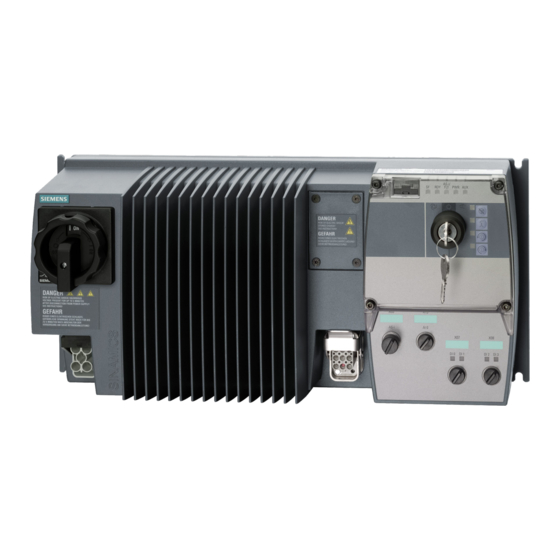
Page 36: General Layout Of Sinamics G110D
Connection 4.2 General layout of SINAMICS G110D General layout of SINAMICS G110D General layout of SINAMICS G110D Image 4-1 Layout of the SINAMICS G110D SINAMICS G110D Operating Instructions, 07/2016, FW V3.63, A5E36768472B AB... -
Page 37: Removal Of Cu Area Cover And Braking Resistor Connection Hatch
Inverter, it is important to ensure that the seals around these areas are fitted properly when reassembling the Inverter to ensure the IP65 rating. TN and TT mains supplies The SINAMICS G110D Inverter with the Class A integrated mains filter is only suitable for operation on TN and TT mains supplies. Image 4-2... -
Page 38: Drill Pattern For The Sinamics G110D
Connection 4.4 Drill pattern for the SINAMICS G110D Drill pattern for the SINAMICS G110D Drill pattern for the SINAMICS G110D Inverter The Inverter has an identical drill pattern for all frame sizes. The drill pattern, depth and tightening torques are shown in the diagram below. -
Page 39: Mounting Orientation
Connection 4.5 Mounting orientation Mounting orientation Correct mounting orientation of the Inverter In the figure below the correct mounting orientation of the Inverter is shown. Image 4-4 Correct Inverter orientation SINAMICS G110D Operating Instructions, 07/2016, FW V3.63, A5E36768472B AB... -
Page 40: Ambient Operating Conditions
If the Inverter is to be installed at an altitude > 1000 m (> 3280 ft) derating will be required. The figures below show the derating required according to altitude. Image 4-6 Derating for altitiude SINAMICS G110D Operating Instructions, 07/2016, FW V3.63, A5E36768472B AB... - Page 41 When fully assembled the inverter has an IP65 rating. This means that the inverter is totally protected against dust and low pressure jets of water. Any unused connections should be covered with the correct sealing caps to ensure the IP65 rating. SINAMICS G110D Operating Instructions, 07/2016, FW V3.63, A5E36768472B AB...
-
Page 42: Sinamics G110D Specifications
Connection 4.7 SINAMICS G110D Specifications SINAMICS G110D Specifications SINAMICS G110D specifications Table 4- 1 Rated Output, Input and Fuses Product Frame Rated output Fuse Circuit breakers size Rated output Rated input 3NA3… current current 6SL3511-… Type Order Number 0PE17-5AM0 0.75... - Page 43 3NA3810 3RV2021…, 3RV1031…, 3RV2031… 3RV1742… Siemens 3NA38 series fuses and 3RV series motor starter protectors of a lower current rating than shown may also be used. Calculation of the feeder protection according to IEC and UL standards Calculation of the feeder protection: ●...
- Page 44 Connection 4.7 SINAMICS G110D Specifications The inverter is suitable for use on a circuit capable of delivering the short circuit current shown in the tables below when protected by the branch circuit protection indicated. Table 4- 5 Non-semiconductor fuses better than RK5 (JDDZ) SINAMICS G110D model no.
- Page 45 Connection 4.7 SINAMICS G110D Specifications Table 4- 7 Branch circuit protection with Type E combination motor controllers (NKJH) SINAMICS G110D CMC model no.* Max. rated current Rated hp at 460 V SINAMICS G110D SCCR model no. with CMC 6SL3511-.PE17-5AM. 3RV20_1-1JA..
- Page 46 *Where “_” in the CMC model no. can be replaced by “1” or “2”. Listed (NKJH) Siemens CMCs of the same type with a current rating lower than that specified in the table, corresponding to SINAMICS G110D drive model number and with a voltage rating of at least 480 V AC may also be used.
-
Page 47: Cables And Connections
24V power supply on the AS-i + / AS-i - pins is provided by the AS-i network itself. In this case additionally a separate independent 24V power supply must be provided on the AUX 24V / 0V pins. SINAMICS G110D Operating Instructions, 07/2016, FW V3.63, A5E36768472B AB... - Page 48 AS-i + / AS-i - pins. This can be the same power supply as connected to the AUX 24V / 0V pins as shown in the block diagram below. Block diagram Image 4-7 SINAMICS G110D block diagram SINAMICS G110D Operating Instructions, 07/2016, FW V3.63, A5E36768472B AB...
- Page 49 4.8 Cables and connections Cable, connectors and tools specifications The detailed specifications for the cables, connectors and tools required to manufacture the necessary cables for the SINAMICS G110D are listed in the following tables. Note NFPA compatibility These devices are intended only for installation on industrial machines in accordance with the "Electrical Standard for Industrial Machinery"...
- Page 50 • Keep the motor terminal box closed whenever the mains is applied to the converter. • Insulate the cables that are not used. • Use appropriate insulation on the cables. SINAMICS G110D Operating Instructions, 07/2016, FW V3.63, A5E36768472B AB...
- Page 51 DI1 or DI3 DI0 or DI2 Functional Earth Shield Functional Earth Type M12 - 5 pole (Female) Spec PNP, SIMATIC-compatible, low < 5 V, high > 10 V, max. input voltage 30V SINAMICS G110D Operating Instructions, 07/2016, FW V3.63, A5E36768472B AB...
- Page 52 AS-i connector specifications ASI connections Function Description AS-i system cable colour ASi+ AS-i positive Yellow AUX- Auxilary 0 V Black ASi- AS-i negative Yellow AUX+ Auxilary 24 V Black Function earth Earth connection SINAMICS G110D Operating Instructions, 07/2016, FW V3.63, A5E36768472B AB...
-
Page 53: Configuring The As-I Slave
The address of a AS-i slave can be assigned using the following methods: ● Addressing off-line using the Siemens Addressing Programmer ● Addressing on-line using the controlling system, such as a PLC via the AS-i Master (it should be noted that only one slave with address 0 may be present on the bus if this method is to be implemented). - Page 54 The equipment shown in the table below will be necessary for the successful integration of more than one Inverter onto the AS-i bus network. Table 4- 20 Equipment for installation of SINAMICS G110D (AS-i) Item Order Number...
- Page 55 4.9 Configuring the AS-i slave Typical AS-i network structure In the diagram below a typical AS-i network is shown to help visualise the structure and arrangement of an AS-i network. Image 4-8 Example AS-i configuration SINAMICS G110D Operating Instructions, 07/2016, FW V3.63, A5E36768472B AB...
- Page 56 Address Programmer. 6. Refit the Control Unit cover, ensure that the seals are correctly in place to preserve the Inverter IP65 rating. SINAMICS G110D Operating Instructions, 07/2016, FW V3.63, A5E36768472B AB...
- Page 57 Connection 4.9 Configuring the AS-i slave Image 4-9 Addressing the ASi slave SINAMICS G110D Operating Instructions, 07/2016, FW V3.63, A5E36768472B AB...
-
Page 58: Using The As-I Programmer
Press the button to confirm the selected address. ProG is momentarily displayed, followed by AddrES. The number allocated to slave 1 is now shown at the bottom of the display. SINAMICS G110D Operating Instructions, 07/2016, FW V3.63, A5E36768472B AB... - Page 59 Press the button to accept this number. ProG is displayed briefly. Both of the numbers allocated to the slaves are now displayed in the lower part of the screen. SINAMICS G110D Operating Instructions, 07/2016, FW V3.63, A5E36768472B AB...
- Page 60 The selected number will begin to flash. Press the buttons to select the new slave address number. Press the button to confirm the new address. ProG is displayed briefly followed by confirmation of the address change. SINAMICS G110D Operating Instructions, 07/2016, FW V3.63, A5E36768472B AB...
-
Page 61: Commissioning
The commissioning scenarios listed below are described in the following sections: ● Commissioning, using the factory settings ● Commissioning with the STARTER software ● Commissioning using the Operator Panel ● Data backup with the SD memory card SINAMICS G110D Operating Instructions, 07/2016, FW V3.63, A5E36768472B AB... - Page 62 Commissioning 5.1 Typical commissioning scenarios Users can access the inverter parameters via the following interfaces Image 5-1 Communication interfaces SINAMICS G110D Operating Instructions, 07/2016, FW V3.63, A5E36768472B AB...
-
Page 63: Restoring The Factory Settings
The following parameters remain unchanged even after the factory settings have been restored: • P0014 Storage mode • P0100 Europe / North America • P0201 Power stack code number • Communication parameters • Power-Module-specific data SINAMICS G110D Operating Instructions, 07/2016, FW V3.63, A5E36768472B AB... -
Page 64: Preparing For Commissioning
Motor data / data on the motor rating plate If you use the STARTER software and a SIEMENS motor, you only have to specify the Order No of the motor. In all other cases, you must read-off the data from the motor rating plate and enter the data into the appropriate parameters. - Page 65 ● Possible setpoint sources [P1000] – Motorized potentiometer – Analog setpoint – Fixed frequency (default setting for the SINAMICS G110D Inverters) – Fieldbus Minimum/maximum frequency of the motor The minimum and maximum frequency with which the motor operates or is limited regardless of the frequency setpoint.
-
Page 66: Prerequisites Of Using The Factory Settings
– where it gets its speed setpoint (setpoint source) - from an analog input (analog setpoint) - as fixed frequency from a digital input (default setting of the SINAMICS G110D) - from the fieldbus interface frequency setpoint source... -
Page 67: Factory Settings For The Inverter
%) when P0100 = 0, then P0309 is irrelevant P0310 [Hz] Rated motor frequency (in accordance with rating plate in Hz) P0311 1395 [rpm] Rated motor speed (in accordance with rating plate in rpm) SINAMICS G110D Operating Instructions, 07/2016, FW V3.63, A5E36768472B AB... - Page 68 (setpoint input) P1080 [Hz] Minimum frequency P1082 [Hz] Maximum frequency P1120 Ramp-up time P1121 Ramp-down time P1300 V/f control with linear characteristic Control mode P3900 No quick commissioning Completes the quick commissioning. SINAMICS G110D Operating Instructions, 07/2016, FW V3.63, A5E36768472B AB...
-
Page 69: Commissioning With Starter
STARTER should be version 4.1 Service Pack 3 or higher. Note PC connection cable 3RK1922-2BP00 Version E02 or higher of the PC connection cable should be used with the SINAMICS G110D/G120D Inverter. SINAMICS G110D Operating Instructions, 07/2016, FW V3.63, A5E36768472B AB... - Page 70 Click OK and the dialog disappears and the normal STARTER screen appears with the project name appears in the project tree on the right-hand side of the screen. Image 5-4 Insert drive Double-click the "Insert single drive unit"; the select drive dialog appears. SINAMICS G110D Operating Instructions, 07/2016, FW V3.63, A5E36768472B AB...
- Page 71 Select the appropriate Inverter and click OK. The inserted drive will appear in the project tree. Image 5-6 Configure drive unit Double-click "configure drive unit"; the select Inverter dialog will appear. SINAMICS G110D Operating Instructions, 07/2016, FW V3.63, A5E36768472B AB...
- Page 72 Summary dialog The summary screen displays the configuration settings that have been completed up to this point of the process. The details of the configuration can be copied to the clipboard and SINAMICS G110D Operating Instructions, 07/2016, FW V3.63, A5E36768472B AB...
- Page 73 Ensure that "Then start commissioning wizard" is selected and click "Finish". The "Control Method" dialog is displayed. Image 5-9 Select control method dialog Select the required control method and click "Next". The command and setpoints source dialog is displayed. SINAMICS G110D Operating Instructions, 07/2016, FW V3.63, A5E36768472B AB...
- Page 74 Click "Next". The drive setting characteristics dialog is displayed. Image 5-11 Select drive settings dialog Select the appropriate settings for your region and supply characteristics. Click "Next". The Motor dialog is displayed. SINAMICS G110D Operating Instructions, 07/2016, FW V3.63, A5E36768472B AB...
- Page 75 Select the type of motor to which the Inverter is connected. Click "Next"; the motor data dialog is displayed. Image 5-13 Motor data dialog Enter the motor data, which can be found on the motor rating plate. Click "Next"; the Motor identification dialog is displayed. SINAMICS G110D Operating Instructions, 07/2016, FW V3.63, A5E36768472B AB...
- Page 76 Click "Next"; the Important parameters dialog is displayed. Image 5-15 Important parameters dialog Enter the values for the listed parameters. Click "Next"; the motor calculation dialog is displayed. SINAMICS G110D Operating Instructions, 07/2016, FW V3.63, A5E36768472B AB...
- Page 77 Select "complete calculation" and click "Next"; the summary screen will be displayed. Image 5-17 Configuration summary The summary information can be copied to the clipboard for pasting into another application, such as, Notepad as a permanent record of the configuration. Click "Finish". SINAMICS G110D Operating Instructions, 07/2016, FW V3.63, A5E36768472B AB...
- Page 78 Press the Start [I] button and the motor calculation will be performed. When this has been completed, the basic commissioning of the Inverter and motor has been completed. Image 5-19 STARTER control panel SINAMICS G110D Operating Instructions, 07/2016, FW V3.63, A5E36768472B AB...
- Page 79 While the STARTER is online and connected to Inverter it is possible to save all the parameter data and configuration data to the Inverter by uploading the data to the Inverter memory. To upload the data to the Inverter, simply press SINAMICS G110D Operating Instructions, 07/2016, FW V3.63, A5E36768472B AB...
-
Page 80: Basic Commissioning With Iop
Select Application Class Select Motor Data Select Enter Motor Data Select Motor Type Select Characteristic Select Continue Input Motor Frequency Input Motor Voltage Input Motor Current Input Power Rating Input Motor Speed SINAMICS G110D Operating Instructions, 07/2016, FW V3.63, A5E36768472B AB... - Page 81 Input Maximum Frequency Input Ramp-up time Input Ramp-down time Summary of Settings - Select Save Settings Continue Settings saved Status Screen displayed On first ON command - Motor ID is performed SINAMICS G110D Operating Instructions, 07/2016, FW V3.63, A5E36768472B AB...
-
Page 82: Example Application
● C: This sensor detects the load leaving the conveyor section. The sensors are directly connected to the Inverter to allow their individual status to be sent to the controlling PLC. SINAMICS G110D Operating Instructions, 07/2016, FW V3.63, A5E36768472B AB... - Page 83 Commissioning 5.8 Example application Image 5-21 Example conveyor application SINAMICS G110D Operating Instructions, 07/2016, FW V3.63, A5E36768472B AB...
- Page 84 Transfers parameter values from RAM to EEPROM Example S7 script and ladder logic The following is an example S7 script which the PLC will use to communicate with the Inverter. Image 5-22 Example S7 script SINAMICS G110D Operating Instructions, 07/2016, FW V3.63, A5E36768472B AB...
- Page 85 Commissioning 5.8 Example application The following is an example ladder logic diagram. Image 5-23 Example S7 ladder logic SINAMICS G110D Operating Instructions, 07/2016, FW V3.63, A5E36768472B AB...
-
Page 86: Backup Data And Storage
Prerequisites for transferring data sets from the IOP to a different Inverter The Inverter to which the parameter set is transferred must be of the same type and have the same firmware release as the source Inverter. SINAMICS G110D Operating Instructions, 07/2016, FW V3.63, A5E36768472B AB... - Page 87 7. When the download or upload has completed, a screen will be displayed stating that the download or upload has been succesful or not. 8. The IOP display will return to the "Up/Download" screen. SINAMICS G110D Operating Instructions, 07/2016, FW V3.63, A5E36768472B AB...
-
Page 88: Saving And Transferring Data Using The Sd Memory Card
Note Location of memory card holder The memory card holder on the SINAMICS G110D is located under the top cover of the Control Unit housing. The memory card must be installed prior to the electrical installation of the Inverter. When re-assembling the housing, it is important to ensure that the seals are replaced correctly because if the seal are not fitted incorrectly it will adversely affect the IP rating of the Inverter. - Page 89 LED lights up. If the download procedure is unsuccessful, F0061 or F0062 is displayed and the • LED "SF" (red) lights up. In this case, make another attempt to transfer data. SINAMICS G110D Operating Instructions, 07/2016, FW V3.63, A5E36768472B AB...
- Page 90 Commissioning 5.9 Backup data and storage SINAMICS G110D Operating Instructions, 07/2016, FW V3.63, A5E36768472B AB...
-
Page 91: Functions
Functions Overview of Inverter functions Image 6-1 Overview of Inverter functions SINAMICS G110D Operating Instructions, 07/2016, FW V3.63, A5E36768472B AB... - Page 92 The motor temperature monitoring is, e.g. set here. The technological functions allow you to activate a motor holding brake or implement a higher-level pressure or temperature control using the technology controller, for example. SINAMICS G110D Operating Instructions, 07/2016, FW V3.63, A5E36768472B AB...
- Page 93 Functions 6.1 Overview of Inverter functions Connection to a fieldbus The SINAMICS G110D Inverter has been designed to operate on an AS-i network, therefore you must connect the following inverter functions with the fieldbus: ● Command sources ● Setpoint sources ●...
-
Page 94: Inverter Control
Just the same as method 3 of the two-wire control, the first three-wire control method is especially suitable for drives where the direction of rotation is manually reversed. SINAMICS G110D Operating Instructions, 07/2016, FW V3.63, A5E36768472B AB... - Page 95 When CW and CCW are simultaneously selected, the motor is stopped. Reversing is possible at any time. 1. Control command: Switch on or switch off the motor CW rotation 2. Control command: Switch on or switch off the motor CCW rotation SINAMICS G110D Operating Instructions, 07/2016, FW V3.63, A5E36768472B AB...
- Page 96 3. Control command: Enter CW or CCW rotation of the motor A detailed description of all of the methods to control a motor can be found in the following sections. SINAMICS G110D Operating Instructions, 07/2016, FW V3.63, A5E36768472B AB...
-
Page 97: Two-Wire Control, Method 1
P0702 = 12 The motor is reversed with digital input 1 Further options: The motor can be reversed with any other digital input, e.g. with digital input 3 via P0704 = 12 SINAMICS G110D Operating Instructions, 07/2016, FW V3.63, A5E36768472B AB... -
Page 98: Two-Wire Control, Method 2
P0702 = 2 CCW rotation is activated with digital input 1 Further options: CCW rotation can be activated with any other digital input, e.g. with digital input 3 via P0704 = 2 SINAMICS G110D Operating Instructions, 07/2016, FW V3.63, A5E36768472B AB... -
Page 99: Two-Wire Control, Method 3
P0702 = 2 CCW rotation is activated with digital input 1 Further options: CCW rotation can be activated with any other digital input, e.g. with digital input 3 via P0704 = 2 SINAMICS G110D Operating Instructions, 07/2016, FW V3.63, A5E36768472B AB... -
Page 100: Three-Wire Control, Method 1
P0703 = 12 CCW rotation is activated with digital input 2 Further options: CCW rotation can be activated with any other digital input, e.g. with digital input 3 via P0704 = 12 SINAMICS G110D Operating Instructions, 07/2016, FW V3.63, A5E36768472B AB... -
Page 101: Three-Wire Control, Method 2
The direction of the motor is reversed with digital input 2 Further options: The direction of the motor can be reversed with any other digital input, e.g. with digital input 3 via P0704 = 12 SINAMICS G110D Operating Instructions, 07/2016, FW V3.63, A5E36768472B AB... -
Page 102: Command Sources
Parameters, to select the source for the inverter control commands Parameters Description P0700 = ... 0: Factory default setting 2: Digital inputs (P0701 … P0705) 4: USS at RS 232 6: Fieldbus (P2050 … P02091) default setting. SINAMICS G110D Operating Instructions, 07/2016, FW V3.63, A5E36768472B AB... -
Page 103: Assigning Functions To Digital Inputs
99), then you must interconnect this digital input to the required control command. If value 99 is assigned to the digital input to define its function, this can only be reversed by restoring the factory setting. SINAMICS G110D Operating Instructions, 07/2016, FW V3.63, A5E36768472B AB... -
Page 104: Controlling The Motor Using The Fieldbus
Control commands using the fieldbus To control the motor using the fieldbus, the inverter must be connected to a higher-level control using the STARTER software tool. For more information, see Chapter "Operation in fieldbus systems". SINAMICS G110D Operating Instructions, 07/2016, FW V3.63, A5E36768472B AB... -
Page 105: Setpoint Sources
Adding setpoints from different sources You can add several setpoints using frequency setpoint source P1000. For more information, see the List Manual (P1000 in the parameter list and function diagram 5000). SINAMICS G110D Operating Instructions, 07/2016, FW V3.63, A5E36768472B AB... -
Page 106: Frequency Setpoint Using Analog Input [P1000=2]
P0758 = 0.0 Value y1 of AI-scaling This parameter shows the amount of x1 as a % of P2000 (refer- ence frequency) P0761 = 0 Width of the AI dead zone SINAMICS G110D Operating Instructions, 07/2016, FW V3.63, A5E36768472B AB... -
Page 107: Using A Motorized Potentiometer As A Setpoint Source
Reference frequency (Hz); An output value of the MOP of 100 % corresponds to the frequency setpoint from P2000. P2000 should be changed, if a maximum frequency greater than 50 Hz is required. SINAMICS G110D Operating Instructions, 07/2016, FW V3.63, A5E36768472B AB... -
Page 108: Using Fixed Frequencies As A Setpoint Source
2091.0 = Parameter, which displays the status of digital input 2. P1021 = 2091.1 Connect fixed frequency 2(FF2) with the status of DI3. 2091.1 = Parameter, which displays the status of digital input 3. SINAMICS G110D Operating Instructions, 07/2016, FW V3.63, A5E36768472B AB... -
Page 109: Running The Motor In Jog Mode (Jog Function)
JOG mode is limited by P1058 or P1059. P1061 = 10 JOG ramp-down time 0 s ... 650 s / 10 s (factory setting) The ramp-down time in seconds from the highest frequency (P1082) to 0. SINAMICS G110D Operating Instructions, 07/2016, FW V3.63, A5E36768472B AB... -
Page 110: Specifying The Motor Speed Via The Fieldbus
To specify the speed of the motor via the fieldbus, the inverter must be connected to a higher-level control via the STARTER software tool. For more information, see "Operation in fieldbus systems". SINAMICS G110D Operating Instructions, 07/2016, FW V3.63, A5E36768472B AB... -
Page 111: Changing Over The Command Data Sets (Manual, Automatic)
This means that as described in the example above, the master control of the inverter can be switched over. All of the switchable parameters for command sources, setpoint sources and status messages with the same index is known as a "command data set". SINAMICS G110D Operating Instructions, 07/2016, FW V3.63, A5E36768472B AB... - Page 112 Functions 6.5 Changing over the command data sets (manual, automatic) Image 6-7 CDS switchover in the inverter SINAMICS G110D Operating Instructions, 07/2016, FW V3.63, A5E36768472B AB...
- Page 113 Number of the command data set to which the data is to be copied (target) P0809.2 = 1 Start copying For an overview of all the parameters that belong to the drive data sets and can be switched, see the List Manual. SINAMICS G110D Operating Instructions, 07/2016, FW V3.63, A5E36768472B AB...
-
Page 114: Setpoint Preparation
The setpoint calculation modifies the speed setpoint, e.g. it limits the setpoint to a maximum and minimum value and using the ramp-function generator prevents the motor from executing speed steps. Image 6-8 Setpoint calculation in the inverter SINAMICS G110D Operating Instructions, 07/2016, FW V3.63, A5E36768472B AB... -
Page 115: Minimum Frequency And Maximum Frequency
The maximum frequency also acts as an important reference value for various inverter functions (e.g. the ramp-function generator). Table 6- 26 Parameters for minimum and maximum frequency Parameter Description P1080 = ... Minimum frequency P1082 = ... Maximum frequency SINAMICS G110D Operating Instructions, 07/2016, FW V3.63, A5E36768472B AB... -
Page 116: Parameterizing The Ramp-Function Generator
The quick-stop function (OFF3) has a separate ramp-down time, which is set with P1135. Note If the ramp-up/down times are too short, the motor accelerates/decelerates with the maximum possible torque and the set times will be exceeded. SINAMICS G110D Operating Instructions, 07/2016, FW V3.63, A5E36768472B AB... - Page 117 P1133 = … Final rounding time for ramp down (in seconds) P1134 = … Rounding type For more information about this function, see the List Manual (function diagram 5300 and the parameter list). SINAMICS G110D Operating Instructions, 07/2016, FW V3.63, A5E36768472B AB...
-
Page 118: Motor Control
Only increase the voltage boost in small steps until satisfactory motor behavior is reached. Excessively high values in P1310 and P1311 can cause the motor to overhead and switch off (trip) the inverter due to overcurrent . SINAMICS G110D Operating Instructions, 07/2016, FW V3.63, A5E36768472B AB... - Page 119 V_StartBoost,100 = sqrt(3) * P0305 * P0350 * (P1312/100) Additional information about this function is provided in the parameter list and in the function diagram 6100 in the List Manual. SINAMICS G110D Operating Instructions, 07/2016, FW V3.63, A5E36768472B AB...
-
Page 120: V/F Control With Parabolic Characteristic
If the load is driving the motor (i.e. the motor is operating as a generator), the motor speed is above the speed setpoint. SINAMICS G110D Operating Instructions, 07/2016, FW V3.63, A5E36768472B AB... -
Page 121: Additional Characteristics Of The V/F Control
P1330 defines the interface via which the voltage setpoint is entered (e.g. analog input → P1330 = 755). For more information about this function, see function diagram 6100 in the List Manual. SINAMICS G110D Operating Instructions, 07/2016, FW V3.63, A5E36768472B AB... -
Page 122: Protection Functions
Further, the frequency inverter protects itself against an excessively high DC link voltage when the motor is regenerating. The load torque monitoring functions provide effective plant and system protection. SINAMICS G110D Operating Instructions, 07/2016, FW V3.63, A5E36768472B AB... -
Page 123: Overtemperature Protection For The Inverter
IGBT Junction temperature (r0037[1]); causes F0004 or F0006. • Delta temperature between heat sink and junction temperature; causes A0504 • and F0006. Inverter I t (r0036); causes A0505 and F0005. • SINAMICS G110D Operating Instructions, 07/2016, FW V3.63, A5E36768472B AB... - Page 124 Temperature monitoring for the motor The implementation of thermal protection for the motor is accomplished using the following types of thermal sensors: ● PTC sensor ● KTY 84 sensor ● ThermoClick sensor ● PT1000 sensor SINAMICS G110D Operating Instructions, 07/2016, FW V3.63, A5E36768472B AB...
- Page 125 2: Fault and shutdown (F0011) (factory setting) P0640 Motor overload factor (entered in % referred to P0305: rated motor current) *You will find detailed information on classifying the cooling technique in EN 60034-6 SINAMICS G110D Operating Instructions, 07/2016, FW V3.63, A5E36768472B AB...
-
Page 126: Overcurrent Protection
Voltage output of I controller Shows the amount by which the I-max controller reduces the inverter output voltage. For more information about this function, see function diagram 6100 in the List Manual. SINAMICS G110D Operating Instructions, 07/2016, FW V3.63, A5E36768472B AB... -
Page 127: Limiting The Maximum Dc Link Voltage
P1254 = … Activates or deactivates automatic detection of the switch-on levels of the V DCmax controller For more information about this function, see function diagram 4600 in the List Manual. SINAMICS G110D Operating Instructions, 07/2016, FW V3.63, A5E36768472B AB... -
Page 128: Load Torque Monitoring (System Protection)
Delay time for the "no load" message Lock protection P2177 = … Delay time for the "motor locked" message Stall protection P2178 = … Delay time for the "motor stalled" message SINAMICS G110D Operating Instructions, 07/2016, FW V3.63, A5E36768472B AB... - Page 129 Delay time for the message "Leave torque monitoring tolerance band" For more information about these functions, see the List Manual (function diagrams 4110, 4130, and 4140 as well as the parameter list). SINAMICS G110D Operating Instructions, 07/2016, FW V3.63, A5E36768472B AB...
-
Page 130: Technological Functions
In this case, the motor converts kinetic energy into electrical energy. ● Regenerative braking is not available on the SINAMICS G110D Inverter. Inverter braking methods Depending on the particular application and the inverter type, there are different technologies to handle regenerative energy. - Page 131 Disadvantages: – A braking resistor is required; braking energy is lost as heat; the permissible load of the braking resistor must be taken into account. SINAMICS G110D Operating Instructions, 07/2016, FW V3.63, A5E36768472B AB...
-
Page 132: Dc Braking
For DC braking, the kinetic energy of the motor and motor load is partially converted into thermal energy. The motor can overheat if braking lasts too long or the drive must be braked too frequently. SINAMICS G110D Operating Instructions, 07/2016, FW V3.63, A5E36768472B AB... - Page 133 ON command is necessary. 6. If the DC brake is enabled again, the braking current P1232 is impressed as long as P1230=1. SINAMICS G110D Operating Instructions, 07/2016, FW V3.63, A5E36768472B AB...
- Page 134 Functions 6.9 Technological functions Image 6-10 DC braking using external selection SINAMICS G110D Operating Instructions, 07/2016, FW V3.63, A5E36768472B AB...
-
Page 135: Dynamic Braking
The temperature of braking resistors increases during operation. For this reason, avoid coming into direct contact with braking resistors. Make sure that the devices are located at sufficient distances from each other and that proper ventilation is provided. SINAMICS G110D Operating Instructions, 07/2016, FW V3.63, A5E36768472B AB... - Page 136 The ON period set here is only effective if the braking resistor has reached its operating temperature. When required, a cold braking resistor is switched-in independent of this parameter **) SIEMENS resistors are designed for 5% ON period SINAMICS G110D Operating Instructions, 07/2016, FW V3.63, A5E36768472B AB...
-
Page 137: Parameterizing A Motor Holding Brake
● Horizontal and vertical conveyors Operating characteristics of the motor holding brake control after an OFF1 and OFF3 command Image 6-12 Function diagram of the motor holding brake control after an OFF1 or OFF3 command SINAMICS G110D Operating Instructions, 07/2016, FW V3.63, A5E36768472B AB... - Page 138 After these control commands, the signal to close the motor holding brake is immediately output independent of the motor speed. Image 6-13 Function diagram, motor holding brake after an OFF2 command SINAMICS G110D Operating Instructions, 07/2016, FW V3.63, A5E36768472B AB...
- Page 139 – To activate the motor holding brake, parameter P1215 must be set to 1. When a motor with a built-in holding brake is commissioned, a "clicking" sound in the motor indicates that the brake has been properly released. SINAMICS G110D Operating Instructions, 07/2016, FW V3.63, A5E36768472B AB...
- Page 140 Table 6- 41 Parameter to force open a motor holding brake Parameter Description P0003 = 3 Enable expert access to parameters P1218 = 1 Forcibly open the motor holding brake SINAMICS G110D Operating Instructions, 07/2016, FW V3.63, A5E36768472B AB...
-
Page 141: Automatic Restart And Flying Restart
Line undervoltage or power failure The power supply for the Control Unit (electronics) of the SINAMICS G110D Inverter is provided by the 24 V supply of the AS-i network. The term "line undervoltage" describes a situation in which the line voltage fails momentarily and is then restored. - Page 142 3. If, for an automatic restart, the inverter is to be connected to an already rotating motor, then the 'flying restart' function should also be activated using P1200. 4. Make sure that this functions properly. SINAMICS G110D Operating Instructions, 07/2016, FW V3.63, A5E36768472B AB...
- Page 143 Otherwise, overcurrent trips will occur. Useful for motors with high inertia loads. Settings 1 to 3 search in both directions. Set- tings 4 to 6 search only in direction of setpoint. SINAMICS G110D Operating Instructions, 07/2016, FW V3.63, A5E36768472B AB...
- Page 144 This behavior is independent of the power failure or line supply undervoltage. • If the ON command is switched-on during the power failure, then an automatic start is always • formed. Possible faults are first automatically acknowledged. SINAMICS G110D Operating Instructions, 07/2016, FW V3.63, A5E36768472B AB...
- Page 145 Fault acknowl- Fault acknowl- Fault acknowl- Fault acknowl- Fault acknowl- Restart edgement + edgement + restart edgement + edgement + edgement + restart restart restart restart *) -- = no action SINAMICS G110D Operating Instructions, 07/2016, FW V3.63, A5E36768472B AB...
-
Page 146: Flying Restart
When this function is enabled (P1200 > 0), all those working with the system must be informed of the following: • The drive starts automatically. • Although the drive is at a standstill, it can be started by the search current. SINAMICS G110D Operating Instructions, 07/2016, FW V3.63, A5E36768472B AB... - Page 147 (entered in %): 10 % ... 200 %, factory setting 100 % Sets the factor by which the output frequency changes during the flying restart to syn- chronize itself with the running motor. SINAMICS G110D Operating Instructions, 07/2016, FW V3.63, A5E36768472B AB...
- Page 148 The "flying restart" function decelerates the motor slightly. The smaller the drive torque, the more the drive is decelerated. The "flying restart" function should not be activated for motors in group drives due to the different coasting characteristics of the individual motors. SINAMICS G110D Operating Instructions, 07/2016, FW V3.63, A5E36768472B AB...
-
Page 149: Pid Technology Controller
P2231 … P2248 Motorized potentiometer P2251 … r2294 Technology controller parameters You will find more information about this function in the parameter list and in (function diagram 5100 of the List manual). SINAMICS G110D Operating Instructions, 07/2016, FW V3.63, A5E36768472B AB... -
Page 150: Logical Functions Using Function Blocks
An example of an AND logic operation, explained in detail, is provided in the Section "BICO technology". For more information about this function, see function diagrams 4800, 4810, 4820, and 4830 in the List Manual. SINAMICS G110D Operating Instructions, 07/2016, FW V3.63, A5E36768472B AB... -
Page 151: Changing Over Drive Data Sets
This means, that as described in the example above, you can switch over all of the settings of the inverter matching the particular motor. All of the switchable parameters of the five functions mentioned above with the same index is known as a "command data set". SINAMICS G110D Operating Instructions, 07/2016, FW V3.63, A5E36768472B AB... - Page 152 Drive data sets can only be changed over in the "ready for operation" state. The switchover time is approx. 50 ms. Exceptions: The ramp-function generator parameters, the ramp-down time for OFF3, and the speed controller gain can be switched during operation. SINAMICS G110D Operating Instructions, 07/2016, FW V3.63, A5E36768472B AB...
- Page 153 Number of the drive data to which the data is to be copied (target) P0819.2 = 1 Start copying For an overview of all the parameters that belong to the drive data sets and can be switched, see the List Manual. SINAMICS G110D Operating Instructions, 07/2016, FW V3.63, A5E36768472B AB...
-
Page 154: Quick Stop Function
The front edge of the load is detected by the sensor, which initiates the Quick Stop function. Image 6-17 Conveyor example 2 The load is then slowed down and stopped. Image 6-18 Conveyor example 3 SINAMICS G110D Operating Instructions, 07/2016, FW V3.63, A5E36768472B AB... - Page 155 There are basically two trigger methods, edge triggered signals or level triggered signals. Each type of triggering method produces a different reaction to the OFF1 command and the restarting of the motor. These reactions are shown in the figures below: SINAMICS G110D Operating Instructions, 07/2016, FW V3.63, A5E36768472B AB...
- Page 156 'Quick Stop override'. The keypad is switched into local mode and by pressing the 'Quick Stop override' button, the motor will be started by the Inverter. See figure below. Image 6-21 Keypad Quick Stop override SINAMICS G110D Operating Instructions, 07/2016, FW V3.63, A5E36768472B AB...
-
Page 157: Operation In Fieldbus Systems
The basic data exchanged is four bits in each direction each time a slave is polled. A second cable is used for an auxiliary 24 V SINAMICS G110D Operating Instructions, 07/2016, FW V3.63, A5E36768472B AB... - Page 158 To address this requirement version 3.0 of the AS-i standard introduced ‘combined transactions’ in which some of the data bits from the basic communications are used to implement a serial interface capable of transferring both cyclic and acyclic data. SINAMICS G110D Operating Instructions, 07/2016, FW V3.63, A5E36768472B AB...
-
Page 159: Connecting The Inverter To As-I Network
Assignment of the M12 connector to connect to the AS-i network The SINAMICS G110D Inverter has one M12 AS-i connection to allow connection the the AS-i network. The pin assigment of the M12 connector is shown in the table below. -
Page 160: Example: Configuring The Inverter On The As-I Network
1LA7060-4AB10 Notes: 1. Cable length depends on the user requirements and cannot be specified. 2. Although the SINAMICS G110D FSA Inverter is specified, all the SINAMICS G110D Inverters are configured in the same manner SINAMICS G110D Operating Instructions, 07/2016, FW V3.63, A5E36768472B AB... - Page 161 Drive ES Basic is the basic software of the engineering system, which combines the drive technology and Siemens controllers. The STEP 7 Manager user interface acts as a basis with which Drive ES Basic is used to integrate drives in the automation environment with respect to communication, configuration and data storage.
- Page 162 This step assumes that the Inverter has been installed and commissioned as previously described in this manual. The SINAMICS G110D Inverter has the equivalent of two slave nodes to be identified to the AS-i network. The simplest way to set the slave addresses is to allow the AS-i master to poll the network, once the Inverter has been installed correctly, and it will automatically assign an address to any slave devices with an address of '0'.
- Page 163 Press the return button (on the far right) to confirm and enter the address into the slaves memory. Repeat this process for the second slave address required by the Inverter. Image 6-26 Setting the address on the Inverter SINAMICS G110D Operating Instructions, 07/2016, FW V3.63, A5E36768472B AB...
- Page 164 CP343-2 in STEP 7. Image 6-27 Properties dialog CP343-2 - addresses The start addresses for both the inputs and outputs must be identical. The default setting for the reserved data length is 16 bytes. SINAMICS G110D Operating Instructions, 07/2016, FW V3.63, A5E36768472B AB...
- Page 165 To configure a specific slave configuration, select the "Slave Configuration" tab. Double-click on the row in the displayed table in which you want to enter an AS-i slave with the corresponding address; this opens the properties dialog for AS-i slaves. SINAMICS G110D Operating Instructions, 07/2016, FW V3.63, A5E36768472B AB...
- Page 166 AS-i A/B slave at the same address in the B address area. ● Siemens slaves - with this option you can configure the AS-i slave by simply selecting the relevant order number from the drop-down list.
- Page 167 As an option, at start-up parameters can be permitted - whether this parameter can be used depends on the slave type. If the AS-i slave does not support the ID1/ID2 codes, the values F (hex) must be entered. SINAMICS G110D Operating Instructions, 07/2016, FW V3.63, A5E36768472B AB...
-
Page 168: As-I Profile
Dual slave mode with extended addressing. Note: After this parameter is changed, the Inverter will perform an AS-i reset in order to load the new profile information. The slave address will be reset to 0. SINAMICS G110D Operating Instructions, 07/2016, FW V3.63, A5E36768472B AB... - Page 169 The second slave (Slave 2) transfers further process data and allows access to basic diagnostic information through the reply to a parameter request. SINAMICS G110D Operating Instructions, 07/2016, FW V3.63, A5E36768472B AB...
- Page 170 ID code ID2 code Description Combi field device Free profile A/B slave The structure and flow of data is given in the diagram below. Image 6-33 Dual slave internal data flow SINAMICS G110D Operating Instructions, 07/2016, FW V3.63, A5E36768472B AB...
- Page 171 Setting the slave addresses to 0 If the addresses are set to 0 on the Inverter it is necessary to power-cycle of the AS-i bus (or by physically disconnecting and reconnecting the slave). SINAMICS G110D Operating Instructions, 07/2016, FW V3.63, A5E36768472B AB...
- Page 172 ID1 Code modification (P2023) Slave mode Parameter.index Default value Permissible range Single slave without extended addressing P2023.1 0…15 Dual slave 1 with extended addressing P2023.0 0…7 Dual slave 2 with extended addressing P2023.1 0…7 SINAMICS G110D Operating Instructions, 07/2016, FW V3.63, A5E36768472B AB...
- Page 173 0: Input 4 is inactive 1: Input 4 is active Serial clock in Clock signal for CTT2 data transfer to AS-i master Serial data in Data signal for CTT2 data transfer to AS-i master SINAMICS G110D Operating Instructions, 07/2016, FW V3.63, A5E36768472B AB...
- Page 174 1: Inverter motor outputs are active Digital input 1 0: Input 1 is inactive 1: Input 1 is active Digital input 2 0: Input 2 is inactive 1: Input 2 is active SINAMICS G110D Operating Instructions, 07/2016, FW V3.63, A5E36768472B AB...
- Page 175 As required by AS-i, all transfers are initiated by the AS-i master and where appropriate, responded to by the slave. Image 6-34 PKW component structure SINAMICS G110D Operating Instructions, 07/2016, FW V3.63, A5E36768472B AB...
- Page 176 PWE in the response contains an error code. SINAMICS G110D Operating Instructions, 07/2016, FW V3.63, A5E36768472B AB...
- Page 177 Change request for a value which is between the lower an the upper limit, but there are other reasons why the change request is not allowed; it is a parameter with defined single values. SINAMICS G110D Operating Instructions, 07/2016, FW V3.63, A5E36768472B AB...
- Page 178 Parameter 3900:3900 = 1 x 2000 + 1900PP = binary 100000 = 1 PNU = 1900 Parameter 4100:4100 = 2 x 2000 + 100PP = binary 010000 = 2 PNU = 100 Image 6-36 IND component structure SINAMICS G110D Operating Instructions, 07/2016, FW V3.63, A5E36768472B AB...
- Page 179 Data of length shorter than that available is packed in the PKE as shown in the figure below. When a complete array is transferred the format below is repeated as many times as required. Image 6-37 PWE component structure SINAMICS G110D Operating Instructions, 07/2016, FW V3.63, A5E36768472B AB...
- Page 180 Inverters will not use the optional extra data and so will transmit an error object of only one byte in length. SINAMICS G110D Operating Instructions, 07/2016, FW V3.63, A5E36768472B AB...
- Page 181 Pyyyy to the number of any other parameter which is a valid BiCo data source will make the value of that parameter appear in the AS-i cyclic data to the master. Image 6-40 Cyclic data input SINAMICS G110D Operating Instructions, 07/2016, FW V3.63, A5E36768472B AB...
- Page 182 PKW read command had been issued for the parameter last accessed. If no previous write or transfer request has been made the SINAMICS G110D Operating Instructions, 07/2016, FW V3.63, A5E36768472B AB...
- Page 183 Note that unlike other inverter communication bus implementations, the parameter data is not cached and so repeated read requests will always result in the most current available data being transferred. Image 6-44 Parameter read request and response SINAMICS G110D Operating Instructions, 07/2016, FW V3.63, A5E36768472B AB...
- Page 184 ‘no error’ and a further word value containing the error code. This request only makes sense for a PKW write command. Image 6-45 Parameter write request and response SINAMICS G110D Operating Instructions, 07/2016, FW V3.63, A5E36768472B AB...
- Page 185 AS-i standard, it will instead respond with error code 4, ‘busy’. Since one second is allowed between the request and response it is extremely unlikely that this code will ever be used. SINAMICS G110D Operating Instructions, 07/2016, FW V3.63, A5E36768472B AB...
-
Page 186: Step 7 Example Conveyor Program
6.11.1.5 Step 7 example conveyor program Overview of example This example, although not specific to the functionality of the SINAMICS G110D Inverter gives an overview of the type of scripting that can be used to generally control a conveyor system. - Page 187 Functions 6.11 Operation in fieldbus systems Image 6-47 Example conveyor application script - main program SINAMICS G110D Operating Instructions, 07/2016, FW V3.63, A5E36768472B AB...
- Page 188 On completion of a belt cycle, the number of items of the belt is recorded. Image 6-48 Example conveyor application script - control of several conveyor belts SINAMICS G110D Operating Instructions, 07/2016, FW V3.63, A5E36768472B AB...
- Page 189 If a fault condition occurs, the belt will be stop until the fault is rectified. The progam utilized block parameters of an elementary data type. Image 6-49 Example conveyor application script - controlling a conveyor belt SINAMICS G110D Operating Instructions, 07/2016, FW V3.63, A5E36768472B AB...
- Page 190 In the figure below, a method of accomplishing the control of a conveyor belt without the use of block parameters is shown. Image 6-50 Example conveyor script - control a conveyor belt without block parameters SINAMICS G110D Operating Instructions, 07/2016, FW V3.63, A5E36768472B AB...
- Page 191 1. A pre-assigned count value needs to be entered prior to the running of the conveyor system. When the count reaches '0', the conveyor belt is stopped. Image 6-51 Example conveyor application script - parts counter with monitor SINAMICS G110D Operating Instructions, 07/2016, FW V3.63, A5E36768472B AB...
- Page 192 In the figure below, a method of accomplishing the counting of items on the conveyor and monitoring the belt without the use of block parameters is shown. Image 6-52 Example conveyor script - parts counter and monitoring without block parameters SINAMICS G110D Operating Instructions, 07/2016, FW V3.63, A5E36768472B AB...
-
Page 193: Example Application
● C: This sensor detects the load leaving the conveyor section. The sensors are directly connected to the Inverter to allow their individual status to be sent to the controlling PLC. SINAMICS G110D Operating Instructions, 07/2016, FW V3.63, A5E36768472B AB... - Page 194 Functions 6.11 Operation in fieldbus systems Image 6-53 Example conveyor application SINAMICS G110D Operating Instructions, 07/2016, FW V3.63, A5E36768472B AB...
- Page 195 Transfers parameter values from RAM to EEPROM Example S7 script and ladder logic The following is an example S7 script which the PLC will use to communicate with the Inverter. Image 6-54 Example S7 script SINAMICS G110D Operating Instructions, 07/2016, FW V3.63, A5E36768472B AB...
- Page 196 Functions 6.11 Operation in fieldbus systems The following is an example ladder logic diagram. Image 6-55 Example S7 ladder logic SINAMICS G110D Operating Instructions, 07/2016, FW V3.63, A5E36768472B AB...
-
Page 197: Service And Maintenance
- Lower power rating If you replace an Inverter by one with the same type and with a lower power rating, then the Inverter must be re-commissioned. SINAMICS G110D Operating Instructions, 07/2016, FW V3.63, A5E36768472B AB... - Page 198 ● How do I load a valid parameter set into my frequency inverter? From the memory card when the frequency inverter is powered-up or by manually downloading a parameters set either from the memory card or from the PC. SINAMICS G110D Operating Instructions, 07/2016, FW V3.63, A5E36768472B AB...
-
Page 199: Replacing The Inverter
When the first node is assigned an address, the second node becomes visible to the network. The second node is then assigned an appropriate address. 10.If required, manually download a valid parameter set. SINAMICS G110D Operating Instructions, 07/2016, FW V3.63, A5E36768472B AB... -
Page 200: Local/Remote Switch Cover
The switch cover is an optional extra and can be ordered using the following order number: 6SL3555-0PL00-2AA0 The layout of the switch cover is shown in the figure below. SINAMICS G110D Operating Instructions, 07/2016, FW V3.63, A5E36768472B AB... - Page 201 Service and maintenance 7.3 Local/remote switch cover Image 7-1 Local/remote switch cover layout SINAMICS G110D Operating Instructions, 07/2016, FW V3.63, A5E36768472B AB...
- Page 202 Jog left Pressing the Jog left button will move the conveyor belt to the left. Jog right Pressing the Jog right button will move the conveyor belt to the right. SINAMICS G110D Operating Instructions, 07/2016, FW V3.63, A5E36768472B AB...
-
Page 203: Repair Switch
(e.g. EN50178) as well as relevant regulations regarding the correct use of tools and personal equipment ( PPE ) still apply. The location of the Repair switch is shown in the figure below. Image 7-2 Repair switch SINAMICS G110D Operating Instructions, 07/2016, FW V3.63, A5E36768472B AB... - Page 204 Inverter or the controlling PLC. It should be noted that although the motor is isolated, communications and commands can be passed between the controlling PLC and the Inverter, for example, parameters can be changed. SINAMICS G110D Operating Instructions, 07/2016, FW V3.63, A5E36768472B AB...
-
Page 205: Messages And Fault Codes
Control Panel setpont fault - no setpoint values from Control Panel during telegram off time. Remedy Check and improve - if necessary - the value in P3984 • Acknowledge fault • If fault persists, contact Service Department or change Inverter. • SINAMICS G110D Operating Instructions, 07/2016, FW V3.63, A5E36768472B AB... -
Page 206: Led States
The Inverter has five main LEDs which are used to indicate the state of the Inverter. Each digital input has its own status LED. These are shown in the figure below. Image 8-1 SINAMICS G110D LEDs In the table below is shown all the possible states of the LEDs and their meaning. SINAMICS G110D... - Page 207 Messages and fault codes 8.2 LED States Table 8- 2 SINAMICS G110D LED states AS-i/FLT Description Flashing Commissioning Flashing Flashing Update from memory card or parameter download General fault Inverter ready or running Flashing No communications between processors within the...
- Page 208 Messages and fault codes 8.2 LED States SINAMICS G110D Operating Instructions, 07/2016, FW V3.63, A5E36768472B AB...
-
Page 209: Technical Data
0.7 ... 0.85 Overload capability The SINAMICS G110D can either be operated with high overload (HO). In order to avoid overtemperature of the Power Module, after the overload, as a minimum its load must decrease back to the base load (HO base load or LO base load). - Page 210 Technical data 9.1 Technical data of the SINAMICS G110D Feature Data Standards UL, CE, C-tick In order that the system is UL-compliant, UL-certified fuses, overload circuit-breakers or branch circuit protection devices must be used Note 1. Under nominal conditions Table 9- 1...
-
Page 211: Pulse Frequency And Current Reduction
Output current at pulse frequency of rating at size current 400 V rating at 4 kHz 6 kHz 8 kHz 10 kHz 12 kHz 14 kHz 16 kHz 0.75 10.2 13.2 11.2 16.2 13.3 11.4 SINAMICS G110D Operating Instructions, 07/2016, FW V3.63, A5E36768472B AB... - Page 212 Technical data 9.2 Pulse frequency and current reduction SINAMICS G110D Operating Instructions, 07/2016, FW V3.63, A5E36768472B AB...
-
Page 213: Electromagnetic Compatibility
European government organization. This approach allows the use of standards that are still in preparation. EMC Standards The SINAMICS G110D Inverters have been tested in accordance with the EMC Product Standard EN 61800-3:2004. SINAMICS G110D Operating Instructions, 07/2016, FW V3.63, A5E36768472B AB... -
Page 214: Classification Of Emc Categories
● Category C3 Power Drive System (PDS) of rated voltage less than 1000 V intended for use in the Second (Industrial) Environment and not intended for use within the First (Domestic) Environment. SINAMICS G110D Operating Instructions, 07/2016, FW V3.63, A5E36768472B AB... - Page 215 Compliance Table Model Remarks Category C1 - First Environment The SINAMICS G110D inverters are not intended for use within the Cate- gory C1 Environment. Category C2 - First Environment - Professional Use Filtered Variants Drives FSA … FSB (400 V, 0.75 kW … 7.5 kW)
-
Page 216: Emc Performance
Appendix A A.1 Electromagnetic compatibility A.1.3 EMC performance EMC Emissions The SINAMICS G110D inverters have been tested in accordance with the emission requirements of the category C2 (domestic) environment. Table A- 2 Conducted & Radiated Emissions EMC Phenomenon Standard Level... - Page 217 Frequency Variation EN 61000-2-4 Nominal 50 Hz or 60 Hz (± 4 %) Class 3 Commutation Notches EN 60146-1-1 Depth = 40 % Class B Area = 250 % x degrees SINAMICS G110D Operating Instructions, 07/2016, FW V3.63, A5E36768472B AB...
-
Page 218: Standards
EN 60204-1 — Safety of machinery –Electrical equipment of machines European Machinery Directive The SINAMICS G110D inverter series does not fall under the scope of the Machinery Directive. However, the products have been fully evaluated for compliance with the essential Health & Safety requirements of the directive when used in a typical machine application. -
Page 219: Index
Download, 88 Break loose torque, 22 Drill pattern, 38 Drive Data Set, DDS, 151 Drive Data Sets, 151 Dynamic braking, 131, 135 Cable lengths, 47 CDS, 111 Classification of EMC performance, 214 SINAMICS G110D Operating Instructions, 07/2016, FW V3.63, A5E36768472B AB... - Page 220 Motor data, 64 Motor holding brake, 137, 138, 139, 140 Harmonic Currents, 216 Motor rating plate, 64 Humidity range, 40 Motor temperature sensor, 125 Motorized potentiometer, 107, 107 mounting orientation, 39 SINAMICS G110D Operating Instructions, 07/2016, FW V3.63, A5E36768472B AB...
- Page 221 Frequency-dependent, 128, 129 Rampup time, Two-wire control, 94, 95 Recommended AS-i connector, 159 Regenerative energy, 130 Relative humidity, 209 Remote, 202 Repair switch, 203 Underwriters Laboratories, 218 Repeater, 159 Up ramp, 22 SINAMICS G110D Operating Instructions, 07/2016, FW V3.63, A5E36768472B AB...
- Page 222 Index Upload, 89 V/f control, 120 Vendor Specific Acyclic Data Transfer, 182 Voltage boost, 118, 119 Voltage input, 106 Water, 41 SINAMICS G110D Operating Instructions, 07/2016, FW V3.63, A5E36768472B AB...