Siemens SINAMICS G110D Operating Instructions Manual
Hide thumbs
Also See for SINAMICS G110D:
- Operating instructions manual (224 pages) ,
- Getting started (64 pages) ,
- Operating instructions manual (100 pages)
Table of Contents
Advertisement
Quick Links
Advertisement
Table of Contents

Related Manuals for Siemens SINAMICS G110D


Summary of Contents for Siemens SINAMICS G110D
- Page 1 SINAMICS G110D Inverter Operating Instructions · May 2009 SINAMICS...
- Page 3 Warnings and cautions Introduction Description SINAMICS Connection SINAMICS G110D Commissioning Functions Operating Instructions Service and maintenance Messages and fault codes Technical data Appendix A Edition 05/2009, Firmware version 3.3 2009-05-15 A5E02385577A AB...
- Page 4 Note the following: WARNING Siemens products may only be used for the applications described in the catalog and in the relevant technical documentation. If products and components from other manufacturers are used, these must be recommended or approved by Siemens. Proper transport, storage, installation, assembly, commissioning, operation and maintenance are required to ensure that the products operate safely and without any problems.
-
Page 5: Table Of Contents
Connection .............................. 31 Procedure for installing the Inverter.....................31 General layout of SINAMICS G110D...................32 Removal of CU area cover and braking resistor connection hatch ..........33 Drill pattern for the SINAMICS G110D ..................34 Mounting orientation ........................35 Ambient operating conditions.......................36 SINAMICS G110D Specifications ....................37 Cables and connections.......................38... - Page 6 Dynamic braking ........................115 6.9.2.4 Parameterizing a motor holding brake ..................117 6.9.3 Automatic restart and flying restart ................... 121 6.9.3.1 Automatic restart ........................121 6.9.3.2 Flying restart ..........................125 6.9.4 PID technology controller ......................127 SINAMICS G110D Operating Instructions, 2009-05-15, A5E02385577A AB...
- Page 7 Repair switch..........................172 Messages and fault codes ........................175 Fault codes..........................175 LED States ..........................176 Technical data ............................177 Technical data of the SINAMICS G110D...................177 Pulse frequency and current reduction ..................178 Appendix A ............................179 Electromagnetic compatibility ....................179 A.1.1 Electromagnetic compatibility ....................179 A.1.2...
-
Page 9: Warnings And Cautions
This equipment is capable of providing internal motor overload protection according to UL508C. Refer to P0610 and P0335, i²t is ON by default. When changing from the ON to OFF-state of an operation if an LED or other similar display SINAMICS G110D Operating Instructions, 2009-05-15, A5E02385577A AB... - Page 10 Before installing and commissioning, please read these safety instructions and warnings carefully and all the warning labels attached to the equipment. Make sure that the warning labels are kept in a legible condition and replace missing or damaged labels. SINAMICS G110D Operating Instructions, 2009-05-15, A5E02385577A AB...
- Page 11 The control cables must be laid separately from the power cables. Carry out the connections as shown in the installation section in this manual, to prevent inductive and capacitive interference from affecting the correct function of the system. SINAMICS G110D Operating Instructions, 2009-05-15, A5E02385577A AB...
- Page 12 (see EN 60204, section 9.2.5.4). Repair WARNING Repairs on equipment may only be carried out by Siemens Service, by repair centers authorized by Siemens or by authorized personnel who are thoroughly acquainted with all the warnings and operating procedures contained in this manual.
-
Page 13: Introduction
– Function diagrams of all of the inverter functions – A list of the fault messages and alarms ● As download: All of the operating instructions, manuals on SINAMICS G110D http://support.automation.siemens.com/WW/view/de/22339653/133300 ● On DVD: SD Manual Collection - all manuals on low-voltage motors, geared motors and low-voltage inverters, 5 languages. -
Page 14: Adapting The Inverter To The Application
Example: P0305 is the parameter for the rated motor current in Amps. This parameter is set during commissioning. You can enter values between 0.01 and 10000. SINAMICS G110D Operating Instructions, 2009-05-15, A5E02385577A AB... -
Page 15: Parameters With Follow-On Parameterization
● New functions are assigned to the digital inputs (P0701 ... P0704) ● Inverter control is interconnected with the signals from the digital inputs (P0800, P0801, P0840, etc.) For more information about follow-on parameterization for P0700, see the List Manual. SINAMICS G110D Operating Instructions, 2009-05-15, A5E02385577A AB... -
Page 16: Frequently Required Parameters
This is how you select the command source of the control signals (ON/OFF, reversing) of the inverter Parameter Description P0700 = 0: Factory default setting 2: Digital inputs 4: USS on RS 232 6: Fieldbus ; default setting SINAMICS G110D Operating Instructions, 2009-05-15, A5E02385577A AB... - Page 17 The voltage boost is effective from standstill up to the rated speed. The voltage boost is independent of the speed. The voltage boost in V is: V_AccBoost,100 = sqrt(3) * P0305 * P0350 * (P1311/100) SINAMICS G110D Operating Instructions, 2009-05-15, A5E02385577A AB...
-
Page 18: Extended Adaptation Of Parameters
BICO technology describes the type of parameterization that can be used to disconnect all the internal signal interconnections between the functions or establish new connections. This is realized using Binectors and Connectors. Hence the name BICO technology. ( Binector Connector Technology) SINAMICS G110D Operating Instructions, 2009-05-15, A5E02385577A AB... - Page 19 BICO symbols, representation, and description Table 2- 9 Binector symbols Abbreviation and symbol Description Function Binector input Binector output Table 2- 10 Connector symbols Abbreviation and symbol Description Function Connector input Connector output SINAMICS G110D Operating Instructions, 2009-05-15, A5E02385577A AB...
-
Page 20: Bico Technology: Example
● The light barrier has been activated ● The protective door is closed The task is realized by inserting free blocks between the digital input 0 and the internal ON command for the motor and interconnecting them. SINAMICS G110D Operating Instructions, 2009-05-15, A5E02385577A AB... - Page 21 When P0701 = 99, the binector input of the ON/OFF1 function (P0840) is available for activation by a signal source other than r0722.0 (in this case r2811). Figure 2-6 Interconnection after insertion of two functions SINAMICS G110D Operating Instructions, 2009-05-15, A5E02385577A AB...
- Page 22 The assignment is always made by entering the number of the connector/binector from which the required input signals are read in a BICO parameter. SINAMICS G110D Operating Instructions, 2009-05-15, A5E02385577A AB...
-
Page 23: Description
The SINAMICS G110D has been designed to provide an adaptable solution to conveyor technology applications. Each SINAMICS G110D Inverter is a complete Power Module and Control Unit in one unique housing which is IP65 rated. The power output range extends from 0.75 kW to 7.5 The optional STARTER software allows commissioning of the Inverter using a PC with the optional optical cables. - Page 24 Description 3.2 Components of the Inverter system Figure 3-1 SINAMICS G110D FSA SINAMICS G110D Operating Instructions, 2009-05-15, A5E02385577A AB...
- Page 25 Description 3.2 Components of the Inverter system Frame size B (FSB) 6SL3511-0PE24-0AM0 - 4.0 kW 6SL3511-1PE24-0AM0 - 4.0 kW with repair switch Figure 3-2 SINAMICS G110D FSB SINAMICS G110D Operating Instructions, 2009-05-15, A5E02385577A AB...
- Page 26 6SL3511-1PE27-5AM0 - 7.5 kW with repair switch Figure 3-3 SINAMICS G110D FSC The inverter is capable of controlling and monitoring the connected motor in a variety of control modes (which can be selected as required). It supports communication with a local or central controller as well as with monitoring devices.
- Page 27 IOP Hand-held Kit The Hand-held Kit supplies the IOP with its own portable power supply which allows the IOP to be used for series commissioning and diagnosis on a number of Inverters. Order number: 6SL3255-0AA00-4HA0 SINAMICS G110D Operating Instructions, 2009-05-15, A5E02385577A AB...
- Page 28 ● RS232 optical cable - order number: 3RK1922-2BP00. Adapter Plate The adapter plate allows the conversion of the M200D motor-starter mounting centres to a SINAMICS G110D configuration and vice versa. Order number: 6SL3263-1GA20-0GA0. SINAMICS G110D Operating Instructions, 2009-05-15, A5E02385577A AB...
- Page 29 Description 3.2 Components of the Inverter system Braking resistors There are three different classes of braking resistors available for use with the Inverter. Table 3- 1 SINAMICS G110D Braking resistors Order Number Description Specification For use with Inverter 6SL3501-0BE08-6AA0 G110D Braking Resistor 390 ohms / 86 watts average 0.75 kW &...
-
Page 31: Connection
● For commissioning, connect either the IOP Hand-held Kit or a PC utilizing the STARTER software and the optical cables. The installation is now completed and the commissioning of the Inverter can now commence. SINAMICS G110D Operating Instructions, 2009-05-15, A5E02385577A AB... -
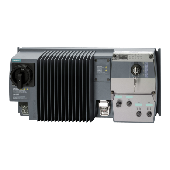
Page 32: General Layout Of Sinamics G110D
Connection 4.2 General layout of SINAMICS G110D General layout of SINAMICS G110D Figure 4-1 SINAMICS G110D Inverter SINAMICS G110D Operating Instructions, 2009-05-15, A5E02385577A AB... -
Page 33: Removal Of Cu Area Cover And Braking Resistor Connection Hatch
Inverter, it is important to ensure that the seals around these areas are fitted properly when reassembling the Inverter to ensure the IP65 rating. TN and TT mains supplies The SINAMICS G110D Inverter with the Class A integrated mains filter is only suitable for operation on TN and TT mains supplies. Figure 4-2... -
Page 34: Drill Pattern For The Sinamics G110D
Connection 4.4 Drill pattern for the SINAMICS G110D Drill pattern for the SINAMICS G110D Drill pattern for the SINAMICS G110D Inverter The Inverter has an identical drill pattern for all frame sizes. The drill pattern, depth and tightening torques are shown in the diagram below. -
Page 35: Mounting Orientation
Connection 4.5 Mounting orientation Mounting orientation Correct mounting orientation of the Inverter In the figure below the correct mounting orientation of the Inverter is shown. Figure 4-4 Correct Inverter orientation SINAMICS G110D Operating Instructions, 2009-05-15, A5E02385577A AB... -
Page 36: Ambient Operating Conditions
If the Inverter is to be installed at an altitude > 1000 m (> 3280 ft) derating will be required. The figures below show the derating required according to altitude. Figure 4-6 Derating for altitiude SINAMICS G110D Operating Instructions, 2009-05-15, A5E02385577A AB... -
Page 37: Sinamics G110D Specifications
Connection 4.7 SINAMICS G110D Specifications Shock and vibration Do not drop the Inverter or expose to sudden shock. Do not install the Inverter in an area where it is likely to be exposed to constant vibration. Electromagnetic radiation Do not install the Inverter near sources of electromagnetic radiation. -
Page 38: Cables And Connections
Inverter. Cables that are not used should be individually insulated and not earthed. The following block diagram and tables describe the details and limitations of the connections of the inverter. SINAMICS G110D Operating Instructions, 2009-05-15, A5E02385577A AB... - Page 39 If the product is not connected to an AS-i network then a 24V power supply still needs to be connected to the AS-i + / AS-i - pins. This can be the same power supply as connected to the AUX 24V / 0V pins as shown in the block diagram below. SINAMICS G110D Operating Instructions, 2009-05-15, A5E02385577A AB...
- Page 40 Connection 4.8 Cables and connections Block diagram Figure 4-7 SINAMICS G110D block diagram SINAMICS G110D Operating Instructions, 2009-05-15, A5E02385577A AB...
- Page 41 4.8 Cables and connections Cable, connectors and tools specifications The detailed specifications for the cables, connectors and tools required to manufacture the necessary cables for the SINAMICS G110D are listed in the following tables. NOTICE NFPA compatibility These devices are intended only for installation on industrial machines in accordance with the "Electrical Standard for Industrial Machinery"...
- Page 42 Function Function Not connected EM Brake (-) Temperature sensor (+) EM Brake (+) Protective Earth Temperature sensor (-) Protective Earth Type HAN Q4/2 (Male) Type HAN Q8 (Female) Spec. 3AC 380V...500V ± Spec. SINAMICS G110D Operating Instructions, 2009-05-15, A5E02385577A AB...
- Page 43 AS-i connector specifications ASI connections Function Description AS-i system cable colour ASi+ AS-i positive Yellow AUX- Auxilary 0 V Black ASi- AS-i negative Yellow AUX+ Auxilary 24 V Black Function earth Earth connection SINAMICS G110D Operating Instructions, 2009-05-15, A5E02385577A AB...
-
Page 44: Configuring The As-I Slave
The address of a AS-i slave can be assigned using the following methods: ● Addressing off-line using the Siemens Addressing Programmer ● Addressing on-line using the controlling system, such as a PLC via the AS-i Master (it should be noted that only one slave with address 0 may be present on the bus if this method is to be implemented). - Page 45 Connection 4.9 Configuring the AS-i slave Table 4- 11 Equipment for installation of SINAMICS G110D (AS-i) Item Order Number Address cable 3RK1901-3HA01 AS-i address programmer 3RK1904-2AB01 AS-i connection kit 3RK1901-1NR21 SINAMICS G110D Operating Instructions, 2009-05-15, A5E02385577A AB...
- Page 46 In the diagram below a typical AS-i network is shown to help visualise the structure and arrangement of an AS-i network. Figure 4-8 Example AS-i configuration Addressing the AS-i device To address the AS-i device (in this case, the Inverter), the following actions should be performed. SINAMICS G110D Operating Instructions, 2009-05-15, A5E02385577A AB...
- Page 47 5. The address of the Inverter (as a slave device) can now be completed. Full instructions are given with the Address Programmer. 6. Refit the Control Unit cover, ensure that the seals are correctly in place to preserve the Inverter IP65 rating. SINAMICS G110D Operating Instructions, 2009-05-15, A5E02385577A AB...
- Page 48 Connection 4.9 Configuring the AS-i slave Figure 4-9 Addressing the ASi slave SINAMICS G110D Operating Instructions, 2009-05-15, A5E02385577A AB...
-
Page 49: Commissioning
The commissioning scenarios listed below are described in the following sections: ● Commissioning, using the factory settings ● Commissioning with the STARTER software ● Commissioning using the Operator Panel ● Data backup with the SD/MMC memory card SINAMICS G110D Operating Instructions, 2009-05-15, A5E02385577A AB... -
Page 50: Restoring The Factory Settings
The IOP will display a message stating that a factory reset is taking place restart from the extras and display a progress bar. When completed the display will display a menu. message that the factory reset has been successfully completed. STARTER Displays a progress bar. SINAMICS G110D Operating Instructions, 2009-05-15, A5E02385577A AB... -
Page 51: Preparing For Commissioning
Motor data / data on the motor rating plate If you use the STARTER software and a SIEMENS motor, you only have to specify the Order No of the motor. In all other cases, you must read-off the data from the motor rating plate and enter the data into the appropriate parameters. - Page 52 There are variety of settings for P1300; the default being 0, which is V/f with linear characteristic. This setting is suitable for most applications. For further information, refer to the Parameter List for the SINAMICS G110D. SINAMICS G110D Operating Instructions, 2009-05-15, A5E02385577A AB...
- Page 53 ● Possible setpoint sources [P1000] – Motorized potentiometer – Analog setpoint – Fixed frequency (default setting for the SINAMICS G110D Inverters) – Fieldbus Minimum/maximum frequency of the motor The minimum and maximum frequency with which the motor operates or is limited regardless of the frequency setpoint.
-
Page 54: Prerequisites Of Using The Factory Settings
– where it gets its speed setpoint (setpoint source) - from an analog input (analog setpoint) - as fixed frequency from a digital input (default setting of the SINAMICS G110D) - from the fieldbus interface frequency setpoint source... - Page 55 Select the source of the frequency setpoint (setpoint input) P1080 [Hz] Minimum frequency P1082 [Hz] Maximum frequency P1120 Ramp-up time P1121 Ramp-down time P1300 V/f control with linear characteristic Control mode P3900 No quick commissioning Completes the quick commissioning. SINAMICS G110D Operating Instructions, 2009-05-15, A5E02385577A AB...
-
Page 56: Commissioning With Starter
STARTER should be version 4.1 Service Pack 3 or higher. Note PC connection cable 3RK1922-2BP00 Version E02 or higher of the PC connection cable should be used with the SINAMICS G110D/G120D Inverter. SINAMICS G110D Operating Instructions, 2009-05-15, A5E02385577A AB... - Page 57 Click OK and the dialog disappears and the normal STARTER screen appears with the project name appears in the project tree on the right-hand side of the screen. Figure 5-4 Insert drive Double-click the "Insert single drive unit"; the select drive dialog appears. SINAMICS G110D Operating Instructions, 2009-05-15, A5E02385577A AB...
- Page 58 Select drive dialog Select the appropriate Inverter and click OK. The inserted drive will appear in the project tree. Figure 5-6 Configure drive unit Double-click "configure drive unit"; the select Inverter dialog will appear. SINAMICS G110D Operating Instructions, 2009-05-15, A5E02385577A AB...
- Page 59 The details of the configuration can be copied to the clipboard and pasted into another application such as Notepad to allow a permanent record of the configuration to be stored. SINAMICS G110D Operating Instructions, 2009-05-15, A5E02385577A AB...
- Page 60 Select the required control method and click "Next". The command and setpoints source dialog is displayed. Figure 5-10 Select command and setpoint source dialog The default command and setpoint source for the Inverter is Fieldbus. SINAMICS G110D Operating Instructions, 2009-05-15, A5E02385577A AB...
- Page 61 Select the appropriate settings for your region and supply characteristics. Click "Next". The Motor dialog is displayed. Figure 5-12 Select motor type dialog Select the type of motor to which the Inverter is connected. Click "Next"; the motor data dialog is displayed. SINAMICS G110D Operating Instructions, 2009-05-15, A5E02385577A AB...
- Page 62 Figure 5-14 Motor identification dialog Select which type of motor identification is required. It is recommended that a motor identification is actually completed. Click "Next"; the Important parameters dialog is displayed. SINAMICS G110D Operating Instructions, 2009-05-15, A5E02385577A AB...
- Page 63 Enter the values for the listed parameters. Click "Next"; the motor calculation dialog is displayed. Figure 5-16 Calculate motor data dialog Select "complete calculation" and click "Next"; the summary screen will be displayed. SINAMICS G110D Operating Instructions, 2009-05-15, A5E02385577A AB...
- Page 64 Figure 5-18 Control panel activation Press the Start [I] button and the motor calculation will be performed. When this has been completed, the basic commissioning of the Inverter and motor has been completed. SINAMICS G110D Operating Instructions, 2009-05-15, A5E02385577A AB...
- Page 65 While the STARTER is online and connected to Inverter it is possible to save all the parameter data and configuration data to the Inverter by uploading the data to the Inverter memory. To upload the data to the Inverter, simply press SINAMICS G110D Operating Instructions, 2009-05-15, A5E02385577A AB...
-
Page 66: Commissioning With The Iop
– The software version and type of Control Unit to which the IOP is fitted. – The firmware and software version of the IOP. – The selected functional group filtering of the parameters. SINAMICS G110D Operating Instructions, 2009-05-15, A5E02385577A AB... - Page 67 The physical layout of the IOP is shown below: Figure 5-21 Layout of IOP The IOP is operated by using a push-wheel and five additional buttons. The specific functions of the push-wheel and buttons are shown in the table below. SINAMICS G110D Operating Instructions, 2009-05-15, A5E02385577A AB...
- Page 68 Locking and unlocking the keypad To lock the IOP keypad press ESC and INFO simultaneously for 3 seconds or more. To unlock the keypad press ESC and INFO simultaneously for 3 seconds or more. SINAMICS G110D Operating Instructions, 2009-05-15, A5E02385577A AB...
- Page 69 Figure 5-22 IOP Handheld Kit Table 5- 4 Handheld device order information Order number Item quantity Item Remarks 6SL3255-0AA00-4HA0 Hand-held module Power supply unit Rechargeable batteries 1.2 V NiMH RS232 cable SINAMICS G110D Operating Instructions, 2009-05-15, A5E02385577A AB...
- Page 70 SINAMICS G110D Inverter. The RS232 optical cable is used to allow the IOP Hand-held device to be connected to the Inverter, utilizing the optical interface on the SINAMICS G110D. Commissioning the Inverter As previously stated, the IOP is a menu driven operator panel. By choosing the appropriate menu options the user will be guide through a series of questions, which when answered, will set the appropriate values for any parameters involving the selected function.
-
Page 71: Example Application
● C: This sensor detects the load leaving the conveyor section. The sensors are directly connected to the Inverter to allow their individual status to be sent to the controlling PLC. SINAMICS G110D Operating Instructions, 2009-05-15, A5E02385577A AB... - Page 72 P3900 = 0. In addition to the AS-i specific parameters discussed in the previous section the following parameters should be modified to allow the digital inputs to be read by the controlling PLC. SINAMICS G110D Operating Instructions, 2009-05-15, A5E02385577A AB...
- Page 73 "G110D _ SLOW" Netzwork: Wait for following conveyor "NextConveyorOccupied" "G110D _ QSdisable" Netzwork: Generate message occupied "G110D _ DI0" "EdgeDI0" "ConveyorOccupied" Figure 5-24 Example S7 script The following is an example ladder logic diagram. SINAMICS G110D Operating Instructions, 2009-05-15, A5E02385577A AB...
- Page 74 "G110D _ "G110D _ Occupied" DI1" SLOW" Network: Wait for following conveyor "NextConveyor "G110D _ Occupied" QSdisable" Network: Generate message occupied "G110D _ "Conveyor "EdgeDI0" DI0" Occupied" Figure 5-25 Example S7 ladder logic SINAMICS G110D Operating Instructions, 2009-05-15, A5E02385577A AB...
-
Page 75: Backup Data And Storage
7. When the download or upload has completed, a screen will be displayed stating that the download or upload has been succesful or not. 8. The IOP display will return to the "Up/Download" screen. SINAMICS G110D Operating Instructions, 2009-05-15, A5E02385577A AB... -
Page 76: Saving And Transferring Data Using The Mmc
Note Location of memory card holder The memory card holder on the SINAMICS G110D is located under the top cover of the Control Unit housing. The memory card must be installed prior to the electrical installation of the Inverter. When re-assembling the housing, it is important to ensure that the seals are replaced correctly because if the seal are not fitted incorrectly it will adversely affect the IP rating of the Inverter. - Page 77 If the upload procedure is successful, P0010 and P0803 are set to 0 and the "RDY" • LED lights up. If the download procedure is unsuccessful, F0061 or F0062 is displayed and the • LED "SF" (red) lights up. In this case, make another attempt to transfer data. SINAMICS G110D Operating Instructions, 2009-05-15, A5E02385577A AB...
-
Page 79: Functions
Functions Overview of Inverter functions Figure 6-1 Overview of Inverter functions SINAMICS G110D Operating Instructions, 2009-05-15, A5E02385577A AB... - Page 80 The motor temperature monitoring is, e.g. set here. The technological functions allow you to activate a motor holding brake or implement a higher-level pressure or temperature control using the technology controller, for example. SINAMICS G110D Operating Instructions, 2009-05-15, A5E02385577A AB...
-
Page 81: Inverter Control
Functions 6.2 Inverter Control Connection to a fieldbus The SINAMICS G110D Inverter has been designed to operate on an AS-i network, therefore you must connect the following inverter functions with the fieldbus: ● Command sources ● Setpoint sources ● Status messages A connection with a fieldbus can be established using software tools in the control systems. - Page 82 The motor cannot be reversed as long as it is still rotating. 1. Control command: Switch on or switch off the motor CW rotation 2. Control command: Switch on or switch off the motor CCW rotation SINAMICS G110D Operating Instructions, 2009-05-15, A5E02385577A AB...
- Page 83 1. Control command: Enable the motor so that it can be switched on or switched off 2. Control command: Switch on the motor CW rotation 3. Control command: Switch on motor CCW rotation SINAMICS G110D Operating Instructions, 2009-05-15, A5E02385577A AB...
-
Page 84: Two-Wire Control, Method 1
This control method uses two control commands as permanent signals. One control command starts/stops the motor, while the other control command changes the direction of rotation. Figure 6-2 Two-wire control using digital inputs, method 1 SINAMICS G110D Operating Instructions, 2009-05-15, A5E02385577A AB... -
Page 85: Two-Wire Control, Method 2
CW and CCW rotation of the motor is started and stopped with one control command each. To change the direction, the drive must first decelerate to 0 Hz with OFF1 before the direction reversal signal is accepted. Figure 6-3 Two-wire control using digital inputs, method 2 SINAMICS G110D Operating Instructions, 2009-05-15, A5E02385577A AB... -
Page 86: Two-Wire Control, Method 3
The motor does not have to coast to 0 Hz either before a control command is executed. Figure 6-4 Two-wire control using digital inputs, method 3 SINAMICS G110D Operating Instructions, 2009-05-15, A5E02385577A AB... -
Page 87: Three-Wire Control, Method 1
● CW rotation is activated with the positive edge of the second control command. ● CCW rotation is activated with the positive edge of the third control command. Figure 6-5 Three-wire control using digital inputs, method 1 SINAMICS G110D Operating Instructions, 2009-05-15, A5E02385577A AB... - Page 88 P0704 = 2 P0703 = 12 CCW rotation is activated with digital input 2 Further options: CCW rotation can be activated with any other digital input, e.g. with digital input 3 via P0704 = 12 SINAMICS G110D Operating Instructions, 2009-05-15, A5E02385577A AB...
-
Page 89: Three-Wire Control, Method 2
The enable signal to power-up the motor is issued with digital input 0 Further options: The enable signal can be issued with any other digital input, e.g. with digital input 3 via P0704 = 2 SINAMICS G110D Operating Instructions, 2009-05-15, A5E02385577A AB... -
Page 90: Command Sources
Assigning control commands to digital inputs as command sources [P0701…P0704] The digital inputs are pre-assigned with certain control commands in the factory. However, these digital inputs can be freely assigned to a control command. SINAMICS G110D Operating Instructions, 2009-05-15, A5E02385577A AB... - Page 91 99), then you must interconnect this digital input to the required control command. If value 99 is assigned to the digital input to define its function, this can only be reversed by restoring the factory setting. SINAMICS G110D Operating Instructions, 2009-05-15, A5E02385577A AB...
-
Page 92: Controlling The Motor Using The Fieldbus
6: Fieldbus Adding setpoints from different sources You can add several setpoints using frequency setpoint source P1000. For more information, see the List Manual (P1000 in the parameter list and function diagram 5000). SINAMICS G110D Operating Instructions, 2009-05-15, A5E02385577A AB... -
Page 93: Frequency Setpoint Using Analog Input [P1000=2]
The last motorized potentiometer setpoint that was active prior to the OFF command or shutdown can be saved. 0: MOP setpoint is not saved (factory setting) 1: MOP setpoint is saved in P1040 SINAMICS G110D Operating Instructions, 2009-05-15, A5E02385577A AB... -
Page 94: Using Fixed Frequencies As A Setpoint Source
Inverter. An example is given below of selecting two fixed frequencies using digital input 2 and 3. SINAMICS G110D Operating Instructions, 2009-05-15, A5E02385577A AB... -
Page 95: Running The Motor In Jog Mode (Jog Function)
When this function is enabled, the motor starts up ("ready for operation" status) when the JOG button is pressed and rotates at the set JOG frequency. When the button is released, the motor stops. This button has no effect when the motor is already running. SINAMICS G110D Operating Instructions, 2009-05-15, A5E02385577A AB... -
Page 96: Specifying The Motor Speed Via The Fieldbus
Specifying the motor speed via the fieldbus To specify the speed of the motor via the fieldbus, the inverter must be connected to a higher-level control via the STARTER software tool. For more information, see "Operation in fieldbus systems". SINAMICS G110D Operating Instructions, 2009-05-15, A5E02385577A AB... -
Page 97: Changing Over The Command Data Sets (Manual, Automatic)
This means that as described in the example above, the master control of the inverter can be switched over. All of the switchable parameters for command sources, setpoint sources and status messages with the same index is known as a "command data set". SINAMICS G110D Operating Instructions, 2009-05-15, A5E02385577A AB... - Page 98 CDS switchover in the inverter The command data sets are switched over using parameters P0810 and P0811. Parameters P0810 and P0811 are interlinked to control commands, e.g. the digital inputs of the inverter, using BICO technology. SINAMICS G110D Operating Instructions, 2009-05-15, A5E02385577A AB...
- Page 99 Number of the command data set to which the data is to be copied (target) P0809.2 = 1 Start copying For an overview of all the parameters that belong to the drive data sets and can be switched, see the List Manual. SINAMICS G110D Operating Instructions, 2009-05-15, A5E02385577A AB...
-
Page 100: Setpoint Preparation
The frequency setpoint is limited to the maximum frequency in both directions of rotation. A message is output if the maximum frequency is exceeded. The maximum frequency also acts as an important reference value for various inverter functions (e.g. the ramp-function generator). SINAMICS G110D Operating Instructions, 2009-05-15, A5E02385577A AB... -
Page 101: Parameterizing The Ramp-Function Generator
Rounding can be used to lengthen the motor acceleration/deceleration times. The ramp- up/down time parameterized in the ramp-function generator is exceeded. SINAMICS G110D Operating Instructions, 2009-05-15, A5E02385577A AB... -
Page 102: Motor Control
Only increase the voltage boost in small steps until satisfactory motor behavior is reached. Excessively high values in P1310 and P1311 can cause the motor to overhead and switch off (trip) the inverter due to overcurrent . SINAMICS G110D Operating Instructions, 2009-05-15, A5E02385577A AB... - Page 103 V_StartBoost,100 = sqrt(3) * P0305 * P0350 * (P1312/100) Additional information about this function is provided in the parameter list and in the function diagram 6100 in the List Manual. SINAMICS G110D Operating Instructions, 2009-05-15, A5E02385577A AB...
-
Page 104: V/F Control With Parabolic Characteristic
(i.e. the motor is operating as a generator), the motor speed is above the speed setpoint. 6.7.4 Additional characteristics of the V/f control In addition to linear and square-law characteristics, there are the following additional versions of the V/f control that are suitable for special applications. SINAMICS G110D Operating Instructions, 2009-05-15, A5E02385577A AB... -
Page 105: Protection Functions
Further, the frequency inverter protects itself against an excessively high DC link voltage when the motor is regenerating. The load torque monitoring functions provide effective plant and system protection. SINAMICS G110D Operating Instructions, 2009-05-15, A5E02385577A AB... -
Page 106: Overtemperature Protection For The Inverter
Inverter I t acts upon output current and output frequency, but not on pulse • frequency. A trip will always result, if the action taken does not sufficiently reduce internal temperatures. SINAMICS G110D Operating Instructions, 2009-05-15, A5E02385577A AB... - Page 107 2: Fault and shutdown (F0011) (factory setting) P0640 Motor overload factor (entered in % referred to P0305: rated motor current) *You will find detailed information on classifying the cooling technique in EN 60034-6 SINAMICS G110D Operating Instructions, 2009-05-15, A5E02385577A AB...
-
Page 108: Overcurrent Protection
Voltage output of I controller Shows the amount by which the I-max controller reduces the inverter output voltage. For more information about this function, see function diagram 6100 in the List Manual. SINAMICS G110D Operating Instructions, 2009-05-15, A5E02385577A AB... -
Page 109: Limiting The Maximum Dc Link Voltage
DCmax P1254 = … Activates or deactivates automatic detection of the switch-on levels of the V DCmax controller For more information about this function, see function diagram 4600 in the List Manual. SINAMICS G110D Operating Instructions, 2009-05-15, A5E02385577A AB... -
Page 110: Load Torque Monitoring (System Protection)
P2181 = … Enable signal for function P2182 = … Frequency threshold 1 P2183 = … Frequency threshold 2 P2184 = … Frequency threshold 3 P2185 = … Upper torque threshold for frequency threshold 1 SINAMICS G110D Operating Instructions, 2009-05-15, A5E02385577A AB... -
Page 111: Technological Functions
● Automatic restart and flying restart ● Basic process control functions ● Logical and arithmetic functions using function blocks that can be freely interconnected Please refer to the following sections for detailed descriptions. SINAMICS G110D Operating Instructions, 2009-05-15, A5E02385577A AB... -
Page 112: Braking Functions
In this case, the motor converts kinetic energy into electrical energy. ● Regenerative braking is not available on the SINAMICS G110D Inverter. Inverter braking methods Depending on the particular application and the inverter type, there are different technologies to handle regenerative energy. -
Page 113: Dc Braking
Operating characteristics of DC braking Figure 6-9 DC braking after an OFF1 or OFF3 command DC braking after an OFF1 or OFF3 command has the following timing sequence: SINAMICS G110D Operating Instructions, 2009-05-15, A5E02385577A AB... - Page 114 1. The function is enabled and selected using BICO parameter P1230 (see figure below). 2. The Inverter pulses are inhibited for the duration of the de-magnetizing time P0347. SINAMICS G110D Operating Instructions, 2009-05-15, A5E02385577A AB...
-
Page 115: Dynamic Braking
An internal chopper control (braking chopper) in the inverter, which can control an external braking resistor, is required for dynamic braking. SINAMICS G110D Operating Instructions, 2009-05-15, A5E02385577A AB... - Page 116 The temperature of braking resistors increases during operation. For this reason, avoid coming into direct contact with braking resistors. Make sure that the devices are located at sufficient distances from each other and that proper ventilation is provided. SINAMICS G110D Operating Instructions, 2009-05-15, A5E02385577A AB...
-
Page 117: Parameterizing A Motor Holding Brake
The ON period set here is only effective if the braking resistor has reached its operating temperature. When required, a cold braking resistor is switched-in independent of this parameter **) SIEMENS resistors are designed for 5% ON period 6.9.2.4 Parameterizing a motor holding brake Motor holding brake applications The motor holding brake prevents the motor turning when the inverter is switched-off. - Page 118 For the OFF2 command the brake closing time is not taken into account. After these control commands, the signal to close the motor holding brake is immediately output independent of the motor speed. SINAMICS G110D Operating Instructions, 2009-05-15, A5E02385577A AB...
- Page 119 – Check the magnetizing time P0346; the magnetizing time is pre-assigned when commissioning the system and must be greater than zero – For V/f operation (P1300 = 0 to 3), set the boost parameters P1310, P1311. SINAMICS G110D Operating Instructions, 2009-05-15, A5E02385577A AB...
- Page 120 "Brake active" status Opening the motor holding brake via P1218 Using parameter P1218, you can force the brake to open, e.g. in order to be able to manually move a conveyor drive. SINAMICS G110D Operating Instructions, 2009-05-15, A5E02385577A AB...
-
Page 121: Automatic Restart And Flying Restart
Line undervoltage or power failure The power supply for the Control Unit (electronics) of the SINAMICS G110D Inverter is provided by the 24 V supply of the AS-i network. The term "line undervoltage" describes a situation in which the line voltage fails momentarily and is then restored. - Page 122 3. If, for an automatic restart, the inverter is to be connected to an already rotating motor, then the 'flying restart' function should also be activated using P1200. 4. Make sure that this functions properly. SINAMICS G110D Operating Instructions, 2009-05-15, A5E02385577A AB...
- Page 123 Faults due to a line supply undervoltage are not automatically acknowledged. • The motor does not automatically start. • The motor only starts to rotate again if an ON command is issued again after the line supply • voltage returns. SINAMICS G110D Operating Instructions, 2009-05-15, A5E02385577A AB...
- Page 124 This behavior is independent of the power failure or line supply undervoltage. • If the ON command is switched-on during the power failure, then an automatic start is always • formed. Possible faults are first automatically acknowledged. SINAMICS G110D Operating Instructions, 2009-05-15, A5E02385577A AB...
-
Page 125: Flying Restart
The "flying restart" function, which is activated by P1200, allows the inverter to be switched to a rotating motor. The function must be used whenever a motor may still be running. This could be: SINAMICS G110D Operating Instructions, 2009-05-15, A5E02385577A AB... - Page 126 Faults • OFF2 • Flying restart active after Search performed in both directions, startup in direction of setpoint Faults • OFF2 • Flying restart always active Search performed in direction of setpoint only SINAMICS G110D Operating Instructions, 2009-05-15, A5E02385577A AB...
-
Page 127: Pid Technology Controller
PID technology controller Technology controller for processing higher-level control functions The technology controller supports all kinds of simple process control tasks. For example, it is used for controlling pressures, levels, or flow rates. SINAMICS G110D Operating Instructions, 2009-05-15, A5E02385577A AB... -
Page 128: Logical Functions Using Function Blocks
● AND blocks, OR blocks, XOR blocks, NOT blocks ● Memory elements Example: OR logic operation You want to switch-on the motor via digital input 0 and also via digital input 1: SINAMICS G110D Operating Instructions, 2009-05-15, A5E02385577A AB... -
Page 129: Changing Over Drive Data Sets
Drive data sets (DDS) The inverter provides the possibility of parameterizing the following functions in up to three different ways: ● Setpoint sources (exceptions: Analog inputs and fieldbus) ● Setpoint calculation ● Motor control SINAMICS G110D Operating Instructions, 2009-05-15, A5E02385577A AB... - Page 130 All of the switchable parameters of the five functions mentioned above with the same index is known as a "command data set". Figure 6-15 Drive Data Sets switchover in Inverter SINAMICS G110D Operating Instructions, 2009-05-15, A5E02385577A AB...
-
Page 131: Quick Stop Function
The Quick Stop function enables a load on a conveyor system to be detected and if Quick Stop is enabled, stop the load on the conveyor section. The load on the conveyor section moves towards a dedicated sensor, as shown in the figure below. Figure 6-16 Conveyor example 1 SINAMICS G110D Operating Instructions, 2009-05-15, A5E02385577A AB... - Page 132 BICO. The signal is expected to be active low (default setting (P0886 = 2). P0883 Quick Stop override Allows Quick Stop override command source to be selected using BICO. The signal is expected to be active high. SINAMICS G110D Operating Instructions, 2009-05-15, A5E02385577A AB...
- Page 133 High level triggered signals reactions The 'Quick Stop override' command is normally sent by the controlling system, but the local keypad can also be used to initiate the 'Quick Stop override'. The keypad is switched into SINAMICS G110D Operating Instructions, 2009-05-15, A5E02385577A AB...
-
Page 134: Operation In Fieldbus Systems
This means that the master polls all the data passed from all the slave nodes at a predefined interval. A typical AS-i network structure is shown in the figure below. SINAMICS G110D Operating Instructions, 2009-05-15, A5E02385577A AB... - Page 135 Inverter. No communications takes place of this second cable. In the diagram below an example is given of how the Manchester coded current pulses are used for communicating data. SINAMICS G110D Operating Instructions, 2009-05-15, A5E02385577A AB...
- Page 136 To address this requirement version 3.0 of the AS-i standard introduced ‘combined transactions’ in which some of the data bits from the basic communications are used to implement a serial interface capable of transferring both cyclic and acyclic data. SINAMICS G110D Operating Instructions, 2009-05-15, A5E02385577A AB...
-
Page 137: Connecting The Inverter To As-I Network
Assignment of the M12 connector to connect to the AS-i network The SINAMICS G110D Inverter has one M12 AS-i connection to allow connection the the AS-i network. The pin assigment of the M12 connector is shown in the table below. -
Page 138: Example: Configuring The Inverter On The As-I Network
1LA7060-4AB10 Notes: 1. Cable length depends on the user requirements and cannot be specified. 2. Although the SINAMICS G110D FSA Inverter is specified, all the SINAMICS G110D Inverters are configured in the same manner SINAMICS G110D Operating Instructions, 2009-05-15, A5E02385577A AB... - Page 139 Drive ES Basic is the basic software of the engineering system, which combines the drive technology and Siemens controllers. The STEP 7 Manager user interface acts as a basis with which Drive ES Basic is used to integrate drives in the automation environment with respect to communication, configuration and data storage.
- Page 140 This step assumes that the Inverter has been installed and commissioned as previously described in this manual. The SINAMICS G110D Inverter has the equivalent of two slave nodes to be identified to the AS-i network. The simplest way to set the slave addresses is to allow the AS-i master to poll the network, once the Inverter has been installed correctly, and it will automatically assign an address to any slave devices with an address of '0'.
- Page 141 Press the return button (on the far right) to confirm and enter the address into the slaves memory. Repeat this process for the second slave address required by the Inverter. Figure 6-26 Setting the address on the Inverter SINAMICS G110D Operating Instructions, 2009-05-15, A5E02385577A AB...
- Page 142 Automatic address programming is set by default, i.e. if a slave is replaced due to a fault, the slave that replaces it will be automatically assigned the previous slaves address. If this action is not required it can be deselected. SINAMICS G110D Operating Instructions, 2009-05-15, A5E02385577A AB...
- Page 143 To configure a specific slave configuration, select the "Slave Configuration" tab. Double-click on the row in the displayed table in which you want to enter an AS-i slave with the corresponding address; this opens the properties dialog for AS-i slaves. SINAMICS G110D Operating Instructions, 2009-05-15, A5E02385577A AB...
- Page 144 AS-i A/B slave at the same address in the B address area. ● Siemens slaves - with this option you can configure the AS-i slave by simply selecting the relevant order number from the drop-down list.
-
Page 145: As-I Profile
The second slave (Slave 2) transfers further process data and allows access to basic diagnostic information through the reply to a parameter request. The details of the individual slave identities are given in the table below: SINAMICS G110D Operating Instructions, 2009-05-15, A5E02385577A AB... - Page 146 The Inverter use a standard M12 connector for connection to the AS-i bus. Since the connection between the inverter and bus is a spur, the Inverter can be disconnected from the bus, the addresses reassigned, and the inverter reconnected without interrupting communications elsewhere on the bus. SINAMICS G110D Operating Instructions, 2009-05-15, A5E02385577A AB...
- Page 147 0: Input 4 is inactive 1: Input 4 is active Serial clock in Clock signal for CTT2 data transfer to AS-i master Serial data in Data signal for CTT2 data transfer to AS-i master SINAMICS G110D Operating Instructions, 2009-05-15, A5E02385577A AB...
- Page 148 In this structure, parameter numbers are paged. Bits 10 - 0 of the PKE comprise the parameter number within a page of 2000 parameters; the page is defined in bits 10 - 15 of the IND word as shown in the figure below. SINAMICS G110D Operating Instructions, 2009-05-15, A5E02385577A AB...
- Page 149 Transfer descriptive element Transfer parameter value (array word) Transfer parameter value (array double word) Transfer number of array elements Cannot process request, task cannot be executed (with error number as describe in table below) SINAMICS G110D Operating Instructions, 2009-05-15, A5E02385577A AB...
- Page 150 Request is not implemented/task not supported 5,10 or 15 PKW request access timeout or number of retries is exceeded or wait for response from CPU side. Parameter value cannot be changed (because parameter is Locked). SINAMICS G110D Operating Instructions, 2009-05-15, A5E02385577A AB...
- Page 151 Data of length shorter than that available is packed in the PKE as shown in the figure below. When a complete array is transferred the format below is repeated as many times as required. SINAMICS G110D Operating Instructions, 2009-05-15, A5E02385577A AB...
- Page 152 Vendor specific write response error error object 0x1D Vendor specific exchange request index, read length, write length, write data 0x5D Vendor specific exchange response ok read data 0x9D Vendor specific exchange response error error object SINAMICS G110D Operating Instructions, 2009-05-15, A5E02385577A AB...
- Page 153 Pxxxx is not connected to any function by default but can be connected to any BiCo connector input as required – e.g. setting the value of P1070 to xxxx would connect the main inverter setpoint to the AS-i cyclic data from the master. SINAMICS G110D Operating Instructions, 2009-05-15, A5E02385577A AB...
- Page 154 0xBB. Figure 6-40 Standard ID read request and response Figure 6-41 Standard diagnostic request and response All other standard acyclic transfer requests will result in a ‘request not implemented’ error response. SINAMICS G110D Operating Instructions, 2009-05-15, A5E02385577A AB...
- Page 155 Note that unlike other inverter communication bus implementations, the parameter data is not cached and so repeated read requests will always result in the most current available data being transferred. SINAMICS G110D Operating Instructions, 2009-05-15, A5E02385577A AB...
- Page 156 ‘no error’ and a further word value containing the error code. This request only makes sense for a PKW write command. SINAMICS G110D Operating Instructions, 2009-05-15, A5E02385577A AB...
- Page 157 A data exchange request first transfers parameter data to the inverter and then transfers the reply back to the master. This request is the ‘normal’ method by which PKW transfers take place in other protocols such as USS or Profibus. SINAMICS G110D Operating Instructions, 2009-05-15, A5E02385577A AB...
-
Page 158: Step 7 Example Conveyor Program
6.11.1.5 Step 7 example conveyor program Overview of example This example, although not specific to the functionality of the SINAMICS G110D Inverter gives an overview of the type of scripting that can be used to generally control a conveyor system. - Page 159 Dura1 Dura2 Load :="Readyload" Q4.0 -- Load new parts onto belt Remove :="Ready_rem" Q4.1 -- Remove parts from belt Network: 6 Block end End: Figure 6-46 Example conveyor application script - main program SINAMICS G110D Operating Instructions, 2009-05-15, A5E02385577A AB...
- Page 160 -- "End of belt" sensor signal conveyor belt 1 Count :=#Count Quantity :=#Quantity :=#Tim Dura1 :=#Dura1 Dura2 :=#Dura2 Finished :="Finished" Q4.2 -- Number of parts reached Fault :="Fault" Q4.3 -- Monitor tripped Network: 4 Block end SINAMICS G110D Operating Instructions, 2009-05-15, A5E02385577A AB...
- Page 161 Figure 6-48 Example conveyor application script - controlling a conveyor belt In the figure below, a method of accomplishing the control of a conveyor belt without the use of block parameters is shown. SINAMICS G110D Operating Instructions, 2009-05-15, A5E02385577A AB...
- Page 162 Parts counter with monitor This program is responsible for counting the actual items on the conveyor belt. This is accomplished using light barriers, which when the item passed the light barrier, the count of SINAMICS G110D Operating Instructions, 2009-05-15, A5E02385577A AB...
- Page 163 Example conveyor application script - parts counter with monitor In the figure below, a method of accomplishing the counting of items on the conveyor and monitoring the belt without the use of block parameters is shown. SINAMICS G110D Operating Instructions, 2009-05-15, A5E02385577A AB...
-
Page 164: Example Application
Commissioning the applications The following information is provided to allow a simple conveyor application to be setup. The logic and control mechanism is provided by a PLC. The conveyor section consists of three sensors: SINAMICS G110D Operating Instructions, 2009-05-15, A5E02385577A AB... - Page 165 ● C: This sensor detects the load leaving the conveyor section. The sensors are directly connected to the Inverter to allow their individual status to be sent to the controlling PLC. Figure 6-52 Example conveyor application SINAMICS G110D Operating Instructions, 2009-05-15, A5E02385577A AB...
- Page 166 "G110D _ SLOW" Netzwork: Wait for following conveyor "NextConveyorOccupied" "G110D _ QSdisable" Netzwork: Generate message occupied "G110D _ DI0" "EdgeDI0" "ConveyorOccupied" Figure 6-53 Example S7 script The following is an example ladder logic diagram. SINAMICS G110D Operating Instructions, 2009-05-15, A5E02385577A AB...
- Page 167 "G110D _ "G110D _ Occupied" DI1" SLOW" Network: Wait for following conveyor "NextConveyor "G110D _ Occupied" QSdisable" Network: Generate message occupied "G110D _ "Conveyor "EdgeDI0" DI0" Occupied" Figure 6-54 Example S7 ladder logic SINAMICS G110D Operating Instructions, 2009-05-15, A5E02385577A AB...
-
Page 169: Service And Maintenance
If you replace an Inverter by one of the same type and the same format, however with a higher power rating, then re-parameterization is not absolutely necessary. However, it is possible that the open-loop control accuracy is therefore reduced. SINAMICS G110D Operating Instructions, 2009-05-15, A5E02385577A AB... -
Page 170: Replacing The Inverter
6. Mount the new Inverter, ensuring that if a memory card is used, it is fitted before mounting the Inverter. 7. Reconnect all the cables and ASi connections. 8. Switch-on the power to the Inverter. SINAMICS G110D Operating Instructions, 2009-05-15, A5E02385577A AB... -
Page 171: Local/Remote Switch Cover
The switch cover is an optional extra and can be ordered using the following order number: 6SL3555-0PL00-2AA0 The layout of the switch cover is shown in the figure below. Figure 7-1 Local/remote switch cover layout SINAMICS G110D Operating Instructions, 2009-05-15, A5E02385577A AB... -
Page 172: Repair Switch
(e.g. EN50178) as well as relevant regulations regarding the correct use of tools and personal equipment ( PPE ) still apply. The location of the Repair switch is shown in the figure below. SINAMICS G110D Operating Instructions, 2009-05-15, A5E02385577A AB... - Page 173 Inverter or the controlling PLC. It should be noted that although the motor is isolated, communications and commands can be passed between the controlling PLC and the Inverter, for example, parameters can be changed. SINAMICS G110D Operating Instructions, 2009-05-15, A5E02385577A AB...
-
Page 175: Messages And Fault Codes
Control Panel setpont fault - no setpoint values from Control Panel during telegram off time. Check and improve - if necessary - the value in P3984 Remedy • Acknowledge fault • If fault persists, contact Service Department or change Inverter. • SINAMICS G110D Operating Instructions, 2009-05-15, A5E02385577A AB... -
Page 176: Led States
LED. These are shown in the figure below. Figure 8-1 SINAMICS G110D LEDs In the table below is shown all the possible states of the LEDs and their meaning. Table 8- 2 SINAMICS G110D LED states AS-i/FLT Description Flashing Commissioning... -
Page 177: Technical Data
0.7 ... 0.85 Overload capability The SINAMICS G110D can either be operated with high overload (HO). In order to avoid overtemperature of the Power Module, after the overload, as a minimum its load must decrease back to the base load (HO base load or LO base load). -
Page 178: Pulse Frequency And Current Reduction
Output current at pulse frequency of rating at size current 400 V rating at 4 kHz 6 kHz 8 kHz 10 kHz 12 kHz 14 kHz 16 kHz 0.75 10.2 13.2 11.2 16.2 13.3 11.4 SINAMICS G110D Operating Instructions, 2009-05-15, A5E02385577A AB... -
Page 179: Electromagnetic Compatibility
This file must be approved by a ‘Competent Body’ appointed by the appropriate European government organization. This approach allows the use of standards that are still in preparation. EMC Standards The SINAMICS G110D Inverters have been tested in accordance with the EMC Product Standard EN 61800-3:2004. A.1.2 Classification of EMC categories... - Page 180 Compliance Table Model Remarks Category C1 - First Environment The SINAMICS G110D inverters are not intended for use within the Category C1 Environment. Category C2 - First Environment - Professional Use Filtered Variants Drives FSA … FSB (400 V, 0.75 kW … 7.5 kW)
-
Page 181: Emc Performance
For further information refer to SIEMENS application note "EMC Design Guidelines". A.1.3 EMC performance EMC Emissions The SINAMICS G110D inverters have been tested in accordance with the emission requirements of the category C2 (domestic) environment. Table A- 2 Conducted & Radiated Emissions... - Page 182 100 % dip for 3 ms Dips 30 % dip for 10 ms 60 % dip for 100 ms 95 % dip for 5000 ms Voltage Distortion EN 61000-2-4 10 % THD Class 3 SINAMICS G110D Operating Instructions, 2009-05-15, A5E02385577A AB...
-
Page 183: Standards
EN 60204-1 — Safety of machinery –Electrical equipment of machines European Machinery Directive The SINAMICS G110D inverter series does not fall under the scope of the Machinery Directive. However, the products have been fully evaluated for compliance with the essential Health & Safety requirements of the directive when used in a typical machine application. -
Page 185: Index
Break loose torque, 17 Download, 76 Drill pattern, 34 Drive Data Set, DDS, 129 Drive Data Sets, 129 Cable connection, 11 Dynamic braking, 113, 115 Cable lengths, 39 CDS, 97 Classification of EMC performance, 179 SINAMICS G110D Operating Instructions, 2009-05-15, A5E02385577A AB... - Page 186 Group fusing, 37 Memory card reader, 28 Minimum frequency, 17, 53, 100 MMC, 49, 76 MMC memory card, 49, 76 mobile radio devices, 9 Harmonic Currents, 182 MOP, 93 Humidity range, 36 Motor connector, 42 SINAMICS G110D Operating Instructions, 2009-05-15, A5E02385577A AB...
- Page 187 Stall protection, 110 PWE components, 151 Standard Acyclic Data Transfer, 154 Standards, 183 STARTER, 49 Starting characteristics Quick Stop function, 131 Optimizing the, 102 Quickstop override, 172 Static discharges, 9 Switches and contactors, 38 SINAMICS G110D Operating Instructions, 2009-05-15, A5E02385577A AB...
- Page 188 Torque monitoring Frequency-dependent, 110 Two-wire control, 81, 82 Underwriters Laboratories, 183 Up ramp, 17 Upload, 77 V/f control, 104 Vendor Specific Acyclic Data Transfer, 155 Voltage boost, 102, 103 Voltage input, 93 Water, 37 SINAMICS G110D Operating Instructions, 2009-05-15, A5E02385577A AB...
- Page 190 Siemens AG Änderungen vorbehalten Industry Sector E86060-KXXXX-AXXX-AX(-XXXX) Postfach 48 48 © Siemens AG 2009 90026 NÜRNBERG DEUTSCHLAND www.siemens.com/automation...