Siemens SINAMICS G150 Operating Manual
Converter cabinet units 75 kw to 800 kw
Hide thumbs
Also See for SINAMICS G150:
- Manual (1843 pages) ,
- Operating instructions manual (680 pages) ,
- Reference manual (38 pages)

Related Manuals for Siemens SINAMICS G150


Summary of Contents for Siemens SINAMICS G150
- Page 1 Operating Manual Edition 11/2003 sinamics Converter Cabinet Units SINAMICS G150 75 kW to 800 kW...
- Page 3 Safety Notes Device Overview Mechanical Installation SINAMICS G150 Electrical Installation Versions A and C Operating Instructions Commissioning User Documentation Operation Setpoint Channel and Closed-Loop Control Output Terminals Monitoring, Functions, and Protective Functions Diagnosis / Faults and Alarms Valid for Maintenance and...
-
Page 4: Contents
We are thankful for any recommendations or suggestions. © Siemens AG 2003. All rights reserved. We reserve the right to make technical changes. Siemens-Aktiengesellschaft SINAMICS G150... - Page 5 Further information is available from: Technical Support Tel: +49 (0) 180 50 50 222 Fax: +49 (0) 180 50 50 223 E-mail adsupport@siemens.com Internet Address Customers can access general and technical information at the following address: http://www.siemens.com/sinamics. SINAMICS G150 Operating Manual...
-
Page 6: Table Of Contents
Other Connections ...................... 4-25 4.9.1 Main Contactor (Option L13) ..................... 4-25 4.9.2 Connection for External Auxiliary Equipment (Option L19)............4-26 4.9.3 Main Circuit-Breaker incl. Fuses/Circuit-Breaker (Option L26) ..........4-27 4.9.4 EMERGENCY OFF Button (Option L45) ................... 4-28 SINAMICS G150 Operating Manual... - Page 7 Minimum Speed........................... 7-3 7.2.3 Speed Limitation.......................... 7-4 7.2.4 Ramp Generator.......................... 7-5 7.2.5 Further Settings ........................... 7-7 Closed-Loop Control ..................... 7-8 Output Terminals Chapter Content ......................8-1 Analog Outputs......................8-2 Digital Outputs....................... 8-6 Further Settings for Analog Outputs................8-8 SINAMICS G150 Operating Manual...
- Page 8 Cabinet Unit Version A, 380 V – 480 V..................12-5 12.3.2 Cabinet Unit Version C, 380 V – 480 V ..................12-8 12.3.3 Cabinet Unit Version A, 660 V – 690 V..................12-11 12.3.4 Cabinet Unit Version C, 660 V – 690 V ................... 12-16 SINAMICS G150 Operating Manual...
-
Page 9: Safety Notes
“Warning” indicates that death, severe personal injury, or substantial property damage can result if proper precautions are not taken. CAUTION “Caution” with a warning triangle indicates that minor personal injury can result if proper precautions are not taken. SINAMICS G150 Operating Manual... - Page 10 National safety guidelines must be observed. Certification The following certificates can be found under “Safety and Operating Instructions” in the documentation folder: • EU declaration of conformity • Certificate of compliance with order • EU manufacturer’s declaration SINAMICS G150 Operating Manual...
-
Page 11: Safety And Operating Instructions
The operating instructions and machine documentation are written in different languages as specified in the delivery contracts. NOTE The services and support provided by the SIEMENS service centers are recommended for planning, installation, commissioning, and servicing work. SINAMICS G150 Operating Manual... - Page 12 • b = ESD table • c = ESD shoes • d = ESD overall • e = ESD chain • f = cubicle ground connection Sitting Standing Sitting / Standing Fig. 1-1 ESD protective measures SINAMICS G150 Operating Manual...
-
Page 13: Device Overview
Chapter Content This chapter provides information on the following: • Introduction to the cabinet units • The main components and features of the cabinet unit • The cabinet unit wiring • Explanation of the type plate SINAMICS G150 Operating Manual... -
Page 14: Applications, Features, Design
SINAMICS G150 takes this into account and, as a result, offers a low-cost drive solution tailored to actual requirements. In addition, factors have been considered to ensure easy handling of the drive from the planning and design phase through to operation. -
Page 15: Design
Helplines and field services are available 24 hours a day, 7 days a week, for support and advice for servicing and ordering spare parts. Design The SINAMICS G150 cabinet units are characterized by their compact, modular, and service-friendly design. A wide range of electrical and mechanical components enable the drive system to be optimized for the appropriate requirements. -
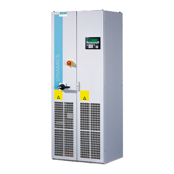
Page 16: Version A
Main circuit-breaker (-Q1) Door lock Custumer terminal block (-A60) Ventilat. grille dep. on degree of protection Power connect. (-X1) Motor connect. (-X2) Fig. 2-1 Example of a cabinet unit, version A (e.g. 132 kW, 400 V) SINAMICS G150 Operating Manual... -
Page 17: Version C
Door lock Customer terminal block (-A60) Ventilation grille dep. on degree of protection Motor connection (-X2) Power connection (-X1) Line reactor (-L1) Fig. 2-2 Example of a cabinet unit, version C (e.g. 315 kW, 690 V) SINAMICS G150 Operating Manual... -
Page 18: Wiring Principle
From an output current of > 800 A, the main circuit-breaker, fuses and main contactor functions are implemented by means of circuit-breakers Fig. 2-3 Wiring principle: versions A and C IMPORTANT The motor earth must be fed back directly to the cabinet unit. SINAMICS G150 Operating Manual... -
Page 19: Type Plate
The date of manufacture can be ascertained as follows: Table 2-1 Year and month of manufacture Letter / Year of manufacture Letter / Month of manufacture number number 2003 1 to 9 January to September 2004 October 2005 November 2006 December SINAMICS G150 Operating Manual... - Page 20 Line reactor u = 2 % for P > 500 kW • − Main circuit-breaker (incl. fuses/circuit-breakers) Output options • − Output filter Input and output options • • EMC shield bus • • PE busbar SINAMICS G150 Operating Manual...
- Page 21 Type plate and operator panel in English / Spanish • • Type plate and operator panel in English / Italian • indicates that this option is available for that version. − indicates that this option is not available for that version. SINAMICS G150 Operating Manual...
- Page 22 Device Overview 11/03 SINAMICS G150 2-10 Operating Manual...
-
Page 23: Mechanical Installation
Mechanical Installation Chapter Content This chapter provides information on the following: • The conditions for transporting, storing, and installing the cabinet unit • Preparing and installing the cabinet unit SINAMICS G150 Operating Manual... -
Page 24: Transportation And Storage
• The degree of protection (IP20, IP21, IP23, IP54) must not be reduced as a result. • The electromagnetic compatibility of the cabinet unit must not be adversely affected. • When control elements are installed on side or rear panels, the panels must be grounded separately. SINAMICS G150 Operating Manual... - Page 25 • If you fail to contact them immediately, you may lose your right to claim compensation for the deficiencies and damage. • If necessary, you can request the support of your local Siemens branch. WARNING Damage in transit indicates that the device was subject to unreasonable stress.
-
Page 26: Installation
When the cable is fed in from above, ensure that enough room is available if the cable has to be bent because of the cable feeder. The cable should be fed in vertically to minimize transverse forces on the entries. SINAMICS G150 Operating Manual... -
Page 27: Preparatory Steps
• Spanner or socket spanner (w/f 13) • Spanner or socket spanner (w/f 18/19) • Hexagon-socket spanner (size 8) • Torque spanner (max. 50 Nm) • Screwdriver (size 2) • Screwdriver (Torx T20) • Screwdriver (Torx T30) SINAMICS G150 Operating Manual... -
Page 28: Installation
(hoods). The filter mediums can be easily fitted and replaced from the outside. Air escapes from the front and back. Compliance with degree of protection IP54 requires an intact filter medium, which must be replaced on a regular basis due to the prevailing ambient conditions. SINAMICS G150 Operating Manual... - Page 29 2. Attach the spacers to the roof of the cabinet at the positions specified. You may have to remove the protective grille. 3. Fit the canopy to the spacers. Attach the supplied bolts from above Attach the supplied bolts from below Fig. 3-1 Cabinet with attached canopy SINAMICS G150 Operating Manual...
- Page 30 • Fit the hood to the roof of the cabinet at the positions specified (fixing points for the crane transport assembly). Attach the original hood bolts (M14) from above Attach the supplied bolts and washers (M8) from below Additional screw fittings are provided for wide hoods Fig. 3-2 Attaching a hood SINAMICS G150 Operating Manual...
-
Page 31: Cable Entry From Above (Option M13), Motor Connection From Above (Option M78)
• Fit the hood to the roof of the cabinet at the positions specified (fixing points for the crane transport assembly). • To secure the power cables, remove the front panel of the hood. SINAMICS G150 Operating Manual... - Page 32 Insert original M14 hood cable entry bolts from above Insert the bolts and washers (M8) supplied from below Additional screw connections are available here for wider hoods Fig. 3-3 Attaching the hood with M13 / M78 SINAMICS G150 3-10 Operating Manual...
-
Page 33: Electrical Installation
• Establishing the electrical connections for the cabinet unit • Adjusting the fan voltage and the internal power supply to local conditions (supply voltage) • The customer terminal block and its interfaces • The interfaces for additional options SINAMICS G150 Operating Manual... -
Page 34: Electrical Installation: Checklist
(-A1-T10) for version A must be adapted to the supply voltage of the cabinet unit (see Section 4.6.3). Before the cabinet is operated from an ungrounded supply/IT supply, the connection bracket for the basic interference suppression device must be removed (see Section 4.6.5). SINAMICS G150 Operating Manual... -
Page 35: Commissioning
L45. OFF category 0 If the cabinet unit is integrated in an external safety (230 V AC / circuit, however, the contact must be looped in via 24 V DC) terminal block -X120 (see Section 4.9.7). SINAMICS G150 Operating Manual... - Page 36 PT100 sensors. The sensors are divided into two groups (see Section 4.9.12). This must be taken into account when the evaluation is performed (factory setting). SINAMICS G150 Operating Manual...
-
Page 37: Required Tools
• Spanner or socket spanner (w/f 13) • Spanner or socket spanner (w/f 18/19) • Hexagon-socket spanner (size 8) • Torque spanner, max. 50 Nm • Screwdriver, size 2 • Screwdriver Torx T20 • Screwdriver Torx T30 SINAMICS G150 Operating Manual... -
Page 38: Important Safety Precautions
These protective covers may have to be removed during installation and connection procedures. Once work has been completed, the protective covers must be properly refitted. SINAMICS G150 Operating Manual... -
Page 39: Operation
Cabinet Assembly • Connect painted or anodized metal components using toothed self-locking screws or remove the insulating layer. • Use unpainted, de-oiled mounting plates. • Establish a central connection between ground and the protective conductor system (ground). SINAMICS G150 Operating Manual... -
Page 40: Cable Installation
> 60 V DC and ≤ 230 V DC unshielded cables for > 25 V AC and ≤ 230 V AC Class 3: – unshielded cables for > 230 V AC/DC and ≤ 1000 V AC/DC SINAMICS G150 Operating Manual... - Page 41 • To improve the EMC properties and depending on the installation location, a radio interference suppression filter is recommended (e.g. option L00 (radio interference suppression filter to EN55011, limit class A1)). SINAMICS G150 Operating Manual...
-
Page 42: Output Terminals
The following table shows the maximum permissible cable lengths (with output filter (option L08) and without output filter) for standard cable types or cable types recommended by SIEMENS. Longer cables can only be used after consultation. The cable lengths specified represent the actual distance between the cabinet unit and the motor, taking into account parallel routing, current-carrying capacity, and the cable-laying factor. -
Page 43: Connecting The Motor And Power Cables
11/03 Electrical Installation NOTE The PROTOFLEX-EMV-3 PLUS shielded cable recommended by Siemens is the protective conductor and comprises three symmetrically arranged protective conductors. The individual protective conductors must each be provided with cable eyes and be connected to ground. The cable also has a concentric flexible braided copper shield. -
Page 44: Adjusting The Fan Voltage (-U1 -T10)
The primary terminals of the transformer may need to be reconnected to the existing supply voltage. The terminals must be connected to "0" and the supply voltage. 380V 400V 440V 480V 600V CON 660V 690V SINAMICS G150 4-12 Operating Manual... - Page 45 Supply voltage assignments for the fan transformer setting (660 V - 690 V) Supply voltage Fan transformer tap (-U1 -T10) 600 V - 630 V 600 V 631 V - 680 V 660 V 681 V - 759 V 690 V SINAMICS G150 4-13 Operating Manual...
-
Page 46: Adjusting The Internal Power Supply (-A1 -T10, Only With Version A)
600 V 1 – 12 631 V - 680 V 660 V 1 – 14, terminals 12 and 13 are bridged 681 V - 759 V 690 V 1 –15, terminals 12 and 13 are bridged SINAMICS G150 4-14 Operating Manual... -
Page 47: Removing The Connection Bracket For The Interference-Suppression Capacitor With Operation From An Ungrounded Supply
If the cabinet unit is operated from an ungrounded supply/IT supply, the connection bracket for the interference-suppression capacitor of the converter (-U1) must be removed. Unscrew bolts M4 (Torx T20) and remove the connection bracket Fig. 4-2 Removing the connection bracket for the interference-suppression capacitor SINAMICS G150 4-15 Operating Manual... -
Page 48: External Supply Of The Auxiliary Supply From A Secure Line
With an external supply independent of the main supply, warnings and fault messages may still be displayed on the operator panel and internal protection and monitoring devices if the main supply fails. SINAMICS G150 4-16 Operating Manual... -
Page 49: Ac Auxiliary Supply
4.7.2 24 V DC Auxiliary Supply The power requirement is 4 A. Connection Connect the external 24 V DC supply to terminals 1 (P 24 V) and 2 (M ext ) of terminal block –X9. SINAMICS G150 4-17 Operating Manual... -
Page 50: Signal Connections
It is important here to establish the greatest possible area of contact and a good conductive connection. NOTE These shield springs can be used for all control cables in the cabinet unit because all the shield connections are identical in design. Fig. 4-3 Shield connection SINAMICS G150 4-18 Operating Manual... - Page 51 S5.1 analog inputs X541 -X521 Digital outputs X521 Analog inputs -X542 -X522 X522 X542 Analog outputs, Relay 1 temperature sensor Relay 2 Shield connection Protective conductor connection M4 Fig. 4-4 Customer terminal block TM31 SINAMICS G150 4-19 Operating Manual...
-
Page 52: Customer Terminal Block
+ 24 V DI/DO 10 + 24 V DI/DO 11 + 24 V X530 X542 DI 4 DO 0 DI 5 DI 6 DI 7 DO 1 Fig. 4-5 Connection overview for customer terminal block TM31 SINAMICS G150 4-20 Operating Manual... - Page 53 Terminal M1 must be connected so that the digital inputs can function correctly. The following solutions are possible: The provided ground reference of the digital inputs, or A jumper to terminal M (Important: electrical isolation for the digital inputs is revoked as a result). SINAMICS G150 4-21 Operating Manual...
- Page 54 Reference potential for AI 1 AI: analog input; P10/N10: auxiliary voltage, M: ground reference Max. connectable cross-section: 1.5 mm² (AWG 14) CAUTION The input current of the analog inputs must not exceed 35 mA when current measurements are performed. SINAMICS G150 4-22 Operating Manual...
- Page 55 X540: Common Auxiliary Voltage for Digital Inputs Table 4-13 Terminal block X540 Terminal Designation Technical data Factory Setting 24 V DC Imax = 150 mA (total of all P24 terminals) Max. connectable cross-section: 1.5 mm² (AWG 14) SINAMICS G150 4-23 Operating Manual...
- Page 56 NO: normally open contact, NC: normally closed contact, COM: mid-position contact Max. connectable cross-section: 2.5 mm² (AWG 12) NOTE If 230 V AC is applied to the relay outputs, the customer terminal block must also be grounded via a 6 mm² protective conductor. SINAMICS G150 4-24 Operating Manual...
-
Page 57: Other Connections
Main Contactor (Option L13) Description The SINAMICS G150 cabinet unit is designed as standard without a line contactor. Option L13 (main contactor) is needed if a switching element is required for disconnecting the cabinet from the supply (necessary with EMERGENCY OFF). -
Page 58: Connection For External Auxiliary Equipment (Option L19)
Circuit Proposal for Controlling the Auxiliary Contactor from Within the Converter The following circuit, for example, can be used if the auxiliary contactor is to be controlled from within the converter. The “Operation” message is then no longer available for other purposes. SINAMICS G150 4-26 Operating Manual... -
Page 59: Main Circuit-Breaker Incl. Fuses/Circuit-Breaker (Option L26)
Max. load current: 10 A Max. switching voltage: 250 V AC Max. switching capacity: 250 VA Required minimum load: ≥1 mA NO: normally open contact, NC: normally closed contact, COM: mid-position contact Max. connectable cross-section: 4 mm² (AWG 10) SINAMICS G150 4-27 Operating Manual... -
Page 60: Emergency Off Button (Option L45)
Max. switching voltage: 250 V AC Max. switching capacity: 250 VA Required minimum load: ≥1 mA NC: normally closed contact Factory setting in converter for options L57, L59, and L60 Max. connectable cross-section: 4 mm² (AWG 10) SINAMICS G150 4-28 Operating Manual... -
Page 61: Cabinet Illumination With Service Socket (Option L50)
(110 V – 230 V AC) must be provided externally and fused at max. 16 A. Connection Table 4-21 Terminal block X240 – connection for cabinet anti-condensation heating Terminal Designation Technical data 110 V -230 V AC power supply Protective conductor Max. connectable cross-section: 4 mm² (AWG 10) SINAMICS G150 4-29 Operating Manual... -
Page 62: Emergency Off Category 0; 230 V Ac Or 24 V Dc (Option L57)
You must also insert the following jumpers at terminal X120: 4-11, 5-10, and 9-14 Diagnostics Messages output during operation and in the event of faults (meaning of LEDs) are described in “Additional Operating Instructions” in the operating manual. SINAMICS G150 4-30 Operating Manual... -
Page 63: Emergency Off Category 1; 230 V Ac (Option L59)
Diagnostics Messages output during operation and in the event of faults (meaning of LEDs) are described in “Additional Operating Instructions” in the operating manual. SINAMICS G150 4-31 Operating Manual... -
Page 64: Emergency Off Category 1; 24 V Dc (Option L60)
Diagnostics Messages output during operation and in the event of faults (meaning of LEDs) are described in “Additional Operating Instructions” in the operating manual. SINAMICS G150 4-32 Operating Manual... -
Page 65: Kw Braking Unit (Option L61); 200 Kw Braking Unit (Option L62)
A ventilation clearance of 200 m must be maintained on all sides of the braking resistor (with ventilation grilles). Table 4-26 Braking resistor dimensions Unit 100 kW resistor (option L61) 200 kW resistor (option L62) Length Width Height 1325 SINAMICS G150 4-33 Operating Manual... - Page 66 Dimension drawing of the braking resistor for option L61 Type plate 1321 2 x threaded bolt T1/T2 screw terminal Ground 2,5 mm² connection 52,5 52,5 Fig. 4-8 Dimension drawing of the braking resistor for option L62 SINAMICS G150 4-34 Operating Manual...
- Page 67 Installing the thermostat for the external braking resistor in the monitoring train of the cabinet unit Terminal Function description Thermostat connection: connection with terminal X541:1 (P24 V) Thermostat connection: connection with terminal X541:5 (DI11) Max. connectable cross-section: 2.5 mm² (AWG 12) SINAMICS G150 4-35 Operating Manual...
- Page 68 • r0721.4 = 1: Chopper is functioning properly • r0721.4 = 0: Chopper is malfunctioning You can acknowledge malfunctions by pressing the "Acknowledge" key on the operator panel (when the DC link voltage is present). SINAMICS G150 4-36 Operating Manual...
- Page 69 This does, 660 V -690 V 1158 V however, reduce the possible peak power (P ) with the square of the voltage (1070/1158)² = 0.85. The possible peak power is, therefore, max. 85 % of P SINAMICS G150 4-37 Operating Manual...
-
Page 70: Thermistor Motor Protection Unit (Option L83/L84)
The PT100 evaluation unit can monitor up to 6 sensors. The sensors can be connected using a two-wire or three-wire system. With the two-wire system, inputs Tx1 and Tx3 must be assigned. With the three-wire system, input Tx2 must also be SINAMICS G150 4-38 Operating Manual... - Page 71 Out 2; sensor group 2 OUT 2 Max. connectable cross-section: 2.5 mm² (AWG 12) Diagnostics Messages output during operation and in the event of faults (meaning of LEDs) are described in "Additional Operating Instructions" in the operating manual. SINAMICS G150 4-39 Operating Manual...
-
Page 72: Insulation Monitor (Option L87))
External test button Max. connectable cross-section: max. 2.5 mm² (AWG 12) Diagnostics Messages output during operation and in the event of faults (meaning of LEDs) are described in "Additional Operating Instructions" in the operating manual. SINAMICS G150 4-40 Operating Manual... -
Page 73: Commissioning
ID • Data backup • Resetting parameters to the factory settings Setpoint channel Closed-loop control Cabinet operator panel PROFIBUS Input terminals Output terminals -A60 -A60 Diagnosis Faults / alarms Monitoring Functions Protective functions SINAMICS G150 Operating Manual... -
Page 74: The Operator Panel
Operating status LEDs: ON (green) Alarm (yellow) Fault (red) 5 function keys Master control Menu key (select) Direction reversal Keyboard lock Increase / Decrease Numeric keypad ON / OFF Fig. 5-1 Components of the cabinet operator panel SINAMICS G150 Operating Manual... -
Page 75: Initial Commissioning
Once the system has successfully ramped up, the drive has to be commissioned when the system is switched on for the first time after it has been delivered. The converter can then be switched on. When the system is then ramped up again, it can be operated immediately. SINAMICS G150 Operating Manual... -
Page 76: Basic Commissioning
Rated output p0307 [kW] / [hp] Rated power factor Cos ϕ (at p0100 = 0 only) p0308 Rated efficiency η (at p0100 = 1 only) p0309 Rated frequency p0310 [Hz] Rated speed p0311 [min-1] / [rpm] SINAMICS G150 Operating Manual... - Page 77 50.0 Hz p0311 MOT.n_Rated 1485.0 min Once you have set and confirmed all the values, xxxxxxxxxxxx press <F5> to continue with basic commissioning. Help Change Continue Bild 5-5 Selecting the motor type and entering the motor data SINAMICS G150 Operating Manual...
- Page 78 Fig. 5-6 Basic commissioning – Further dialog screens, concluding with the motor ID SINAMICS G150 Operating Manual...
- Page 79 Entering the rated magnetization current p0320 = Enter the value read in r0027 in p0320 Storing the parameters p0977 = 1 All the parameter settings will be stored on the CompactFlash Card. Fig. 5-7 Procedure for improving closed-loop control SINAMICS G150 Operating Manual...
-
Page 80: Status After Commissioning
• The actual current value (r0068) is output as a current output in the range 0 to 20 mA at analog output 1 (X522:5 and 6). A current of 20 mA is equal to the current limit (p0640) set to 1.5 x rated motor current (p0305). SINAMICS G150 Operating Manual... -
Page 81: Data Backup
CompactFlash card. NOTE You should only remove the CompactFlash card when the system is switched off. If you remove it while the system is switched on, warning A1100 ("CompactFlash Card removed") is output. SINAMICS G150 Operating Manual... -
Page 82: Restoring The Saved Configuration
Set p0009 = 30 in the following dialog screen Resetting all the parameters to the factory settings p0976 = All the cabinet unit parameters are reset the SINAMICS G150 factory settings - 380 V - 480 V, 110 kW - 250 kW: p0976 = 20... -
Page 83: Operation
• Control via the operator panel • Control via the terminal block • Control via PROFIBUS Setpoint channel Closed-loop control Cabinet operator panel PROFIBUS Input terminals Output terminals -A60 -A60 Diagnosis Faults / alarms Monitoring Functions Protective functions SINAMICS G150 Operating Manual... - Page 84 Fig. 6-1 Control sources Priority The priority of the control sources is shown in Fig. 6-1. NOTE Emergency OFF signals (L57, L59, L60) and motor protection signals (L83, L84) are always active (regardless of the control source). SINAMICS G150 Operating Manual...
-
Page 85: Control Via The Operator Panel
Press "F2" and "F3" to navigate through the menu M a i n m e n u options in the main menu. Fault memory / Alarm memory Settings AOP30 - diagnosic Drive commisioning Device commisioning Help Select. Fig. 6-2 Main menu SINAMICS G150 Operating Manual... -
Page 86: Menu Structure Of The Operator Panel
Set date / time Language switch Reset system settings Software / AOP30-Diagnostic database version Battery status Drive Communication commisioning Keyboard Device commisioning Safety locks Operat. lock Parameteriz. lock Access level Fig. 6-3 Menu structure of the operator panel SINAMICS G150 Operating Manual... - Page 87 In LOCAL control mode, you can choose to enter the setpoint numerically (F2: setpoint). Settings When you choose Settings – Define operation screen, you can adjust the type of display and the values displayed as required. See Section 6.2.2.3 SINAMICS G150 Operating Manual...
-
Page 88: Menu Settings
In this menu, you set the lighting, brightness, and contrast for the display. Defining the Operation Screen In this menu, you can switch between four operation screens. By pressing F3 – "Values", you can set the parameters that are to be displayed. SINAMICS G150 Operating Manual... - Page 89 OPERATION 12:25:30 S Entry 01 Entry 02 Entry 01 Entry 03 Entry 04 100% Entry 02 Entry 05 100% 100% Entry 03 Entry 06 100% 100% Fig. 6-5 Position of the entries in the operation screen SINAMICS G150 Operating Manual...
- Page 90 Analog input 1 [V, mA] r4052[1] V, mA V: 100 V mA: 100 mA Analog input 0, scaled r4055[0] V: 10 V mA: 20 mA Analog input 1, scaled r4055[1] V: 10 V mA: 20 mA SINAMICS G150 Operating Manual...
-
Page 91: Setting The Language
When you reset parameters, all settings that are different to the factory settings are reset immediately. This may cause the cabinet unit to switch to a different, unwanted operational status. For this reason, you should always take great care when resetting parameters. SINAMICS G150 Operating Manual... -
Page 92: Battery Status
You can press the keys in any order you wish. You cannot exit the screen (F5 – "back") until you have pressed each key at least once. SINAMICS G150 6-10 Operating Manual... -
Page 93: Operation Via The Operator Panel (Local Mode)
LOCAL/REMOTE Key Activate LOCAL mode: press the LOCAL key LOCAL mode: LED lights up REMOTE mode : LED does not light up: the ON, OFF, JOG, direction reversal, faster, and slower keys are not active. SINAMICS G150 6-11 Operating Manual... - Page 94 Red OFF key acts as : (factory setting: OFF1) • OFF1 : Ramp-down on the deceleration ramp (p1121) • OFF2 : Immediate pulse block, motor coasts to a standstill • OFF3 : Ramp-down on the emergency stop ramp (p1135) SINAMICS G150 6-12 Operating Manual...
- Page 95 When you enter values numerically, you can enter any speed between the minimum speed (p1080) and the maximum speed (p1082). Setpoint entry in LOCAL mode is unipolar. You can change the direction of rotation by pressing the +/- keys (see Section 6.2.3.4). SINAMICS G150 6-13 Operating Manual...
-
Page 96: Motor Potentiometer
Two key icons appear in the top right of the display when these inhibit functions are enabled. Table 6-3 Display for operator input / parameterization inhibit Inhibit type Online operation Offline operation No inhibit Operator Input Inhibit Parameterization Inhibit Operator input inhibit + parameterization inhibit SINAMICS G150 6-14 Operating Manual... - Page 97 You need a password to activate this level. To activate expert mode, enter code number "47". The "Expert" access level is not stored permanently, which means that it must be reactivated every time the power is switched on. SINAMICS G150 6-15 Operating Manual...
-
Page 98: Faults And Alarms
Fault and Alarm Displays Every fault and alarm is entered in the fault/alarm buffer along with time the error occurred and the time it was rectified. The time stamp relates to the relative system time in milliseconds (r0969). SINAMICS G150 6-16 Operating Manual... -
Page 99: Saving The Parameters Permanently
If you press "Yes", the system saves the setting in the EEPROM. If you press "No", the setting is not saved permanently and the "S" starts flashing. In both cases, all changes that have not yet been saved permanently are stored in the EEPROM. SINAMICS G150 6-17 Operating Manual... -
Page 100: Parameterization Errors
(the eighth or lowest line in the operation screen, or the seventh line in all other screens). The system displays: Parameter write error (d)pxxxx.yy:0xnn and a plain-text explanation of the type of parameterization error. SINAMICS G150 6-18 Operating Manual... -
Page 101: Control Via The Terminal Block
The customer terminal block (-A60) is available as a control interface for the customer. You can use this interface to connect the system to the higher-level controller using analog and digital signals, or connect additional devices. The customer terminal block is a type TM31 module. SINAMICS G150 6-19 Operating Manual... -
Page 102: Analog Inputs
X521 S5.0 AI 0+ AI 0- 20 mA = n max AI 1+ (p2000) AI 1- X520 ON/OFF1 DI 0 DI 1 DI 2 Fault ack. DI 3 Fig. 6-8 Proposed connection assignment SINAMICS G150 6-20 Operating Manual... -
Page 103: Setting Parameters
The unit is V when the analog input is set as a voltage input (p4056 = 0 / 4) and switch S5.0 is set to "V". The unit is mA when the analog input is set as a current input (p4056 = 2 / 3 / 5) and switch S5.0 is set to "I". SINAMICS G150 6-21 Operating Manual... - Page 104 FaultValue: 0000000003 00000003(hex) Component ID Cause: 3: Modul -A60 TM31.Wire break analog input 4: Modul -A61 (option) Remedy: TM31.Check Cable. Anal.Input 0: Analog input 0: -X521:1/2 xxxxxxxxxxxxxxxxxxxxxxxxxxxxx 1: Analog input 1: -X521:3/4 Back Fig. 6-11 Fault screen SINAMICS G150 6-22 Operating Manual...
-
Page 105: Motor Potentiometer
-A10 (CU 320) -A60 (TM31) X540 1: Terminal X530 PROFIBUS/ block DI 4 terminal block X520 DI 0 ON/OFF1 DI 1 Motor potentiometer UP DI 2 Motor potentiometer DOWN DI 3 Fault ack. Fig. 6-12 Circuit proposal SINAMICS G150 6-23 Operating Manual... - Page 106 Motor potentiometer ramp- p1048 down time Factory setting: 10.000 s Ramp-down time entry for the motor potentiometer. Motor potentiometer speed r1050 setpoint downstream of ramp Unit: 1/min generator Display the setpoint downstream of the motor potentiometer. SINAMICS G150 6-24 Operating Manual...
-
Page 107: Fixed Speed Setpoints
DI 5 Fixed setpoint selection DI 6 bit 0 DI 7 Fixed setpoint selection bit 0 X520 DI 0 ON/OFF1 DI 1 DI 2 DI 3 Fault ack. Fig. 6-14 Proposed connection assignment SINAMICS G150 6-25 Operating Manual... - Page 108 Setting range: -210000.000 ... +210000.000 1/min p1003 Fixed speed setpoint 03 Factory setting: 1500.000 1/min Entry for the third fixed speed setpoint. r1024 Fixed speed setpoint active Unit: 1/min Display the active fixed speed setpoint. SINAMICS G150 6-26 Operating Manual...
-
Page 109: Further Settings For Analog Inputs
"I". Setting range: -1000.00 ... +1000.00 % Value y1 for the analog input p4058[0] characteristic Factory setting: 0.00 % Setting for the y coordinate in % of the first point on the scaling characteristic. SINAMICS G150 6-27 Operating Manual... - Page 110 "I". Setting range: -1000.00 ... +1000.00 % Value y2 for the analog input p4060[0] characteristic Factory setting: 100.00 % Setting for the y coordinate in % of the second point on the scaling characteristic. SINAMICS G150 6-28 Operating Manual...
-
Page 111: Control Via Profibus
PROFIBUS Connection Position, Address Switch, and Diagnostic LED The PROFIBUS connection, address switch, and diagnostics LED are located on the control unit. LEDs X126 PROFIBUS- PROFIBUS Connection Diagnostic-LED PROFIBUS Address Switch Fig. 6-17 View of the control unit with PROFIBUS interface SINAMICS G150 6-29 Operating Manual... - Page 112 Principle: the terminating resistors must only be switched on at both ends of the bus line; the resistors must be switched off at all other connectors. The cable shield must be connected at both ends with the greatest possible surface area. SINAMICS G150 6-30 Operating Manual...
-
Page 113: Cable Routing
Route bus cable along available cable line and fasten it to this line with cable ties To pass the cable through, the bus connector has to be dismantled Shield connection Fig. 6-20 Cable routing SINAMICS G150 6-31 Operating Manual... -
Page 114: Control Via Profibus
S1 to S7 are set to ON or OFF. In this case, changes become effective immediately. Table 6-6 PROFIBUS address switches Switch Significance Technical data Significance = 16 Example = 32 = 64 = 37 SINAMICS G150 6-32 Operating Manual... -
Page 115: Process Data
1: Control words and setpoints are analyzed 1 = Control via PLC 0: Control words and setpoints are not analyzed 1 = Direction reversal – reserved – 1 = Increase motor – potentiometer 1 = Decrease motor – potentiometer reserved – SINAMICS G150 6-33 Operating Manual... -
Page 116: Status Word
Table 6-9 Message frame type options Type PZD 1 PZD 2 PZD 3 PZD 4 PZD 5 PZD 6 CW 1 N_SETP SW 1 N_ACT CW 1 N_SETP I_ACT M_ACT P_ACT FAULT SW 1 N_ACT SINAMICS G150 6-34 Operating Manual... -
Page 117: Setpoint Channel And Closed-Loop Control
Minimum speed – Speed limitation – Ramp generator – • Closed-loop control (in preparation) Setpoint channel Closed-loop control Cabinet operator panel PROFIBUS Input terminals Output terminals -A60 -A60 Diagnosis Faults / alarms Monitoring Functions Protective functions SINAMICS G150 Operating Manual... -
Page 118: Setpoint Channel
Prerequisites Direction reversal is triggered: • via PROFIBUS by means of control word 1, bit 11 • via the cabinet operator panel (LOCAL mode) with the "direction reversal" key. SINAMICS G150 Operating Manual... -
Page 119: Minimum Speed
Minimum speed Factory setting: 0.000 1/min Setting parameter for the minimum speed. This speed is not undershot during operation. r1112 Speed setpoint after minimum limit Unit: 1/min Display of speed setpoint after the minimum limit. SINAMICS G150 Operating Manual... -
Page 120: Speed Limitation
Speed limit negative direction of p1086 rotation Factory setting: -210000.000 1/min Setting parameter for the speed limit in a negative direction of rotation. If required, this parameter can be used to disable the negative direction of rotation. SINAMICS G150 Operating Manual... -
Page 121: Ramp Generator
Signal Flow Diagram RG.T_Ramp_Up RG.T_InitRnd RG.T_FInRnd RG.T_Ramp_Down 0.00...999999.00 s 0.00...30.00 s 0.00...30.00 s 0.00...999999.00 s p1120 (10.00) p1130 (0.00) p1131 (0.00) p1121 (10.00) nSetbefore_RG nSetp_after_RG r1119 r1150 p1130 p1131 p1130 p1131 Fig. 7-3 Signal flow diagram: Ramp generator SINAMICS G150 Operating Manual... - Page 122 Setting for the end rounding time. The value applies to ramp-up and ramp-down. NOTE The effective ramp-up time increases when you enter a start and end rounding time. Effective ramp-up time = p1120 + (0.5 x p1130) + (0.5 x p1131) SINAMICS G150 Operating Manual...
-
Page 123: Further Settings
Suppress. speed 1 Suppress. speed 4 p1091 p1094 Suppress. speed 2 Suppress. speed 3 p1092 p1093 Minimum speed p1080 Setp_after_Lim nSet_afterSkip r1114 r1112 Minimum speed n_Suppr.Bandwidth p1101 Fig. 7-4 Signal flow diagram: Suppression speeds and minimum speeds SINAMICS G150 Operating Manual... -
Page 124: Closed-Loop Control
Factory setting: 0.000 1/min Setting parameter for suppression speed 4. Setting range: 0.000 ... +210000.000 1/min p1101 Suppression speed bandwidth Factory setting: 0.000 1/min Setting for the bandwidth for suppression speeds 1 to 4. Closed-Loop Control (in preparation) SINAMICS G150 Operating Manual... -
Page 125: Output Terminals
Output Terminals Chapter Content This chapter provides information on: • Analog outputs • Digital outputs Setpoint channel Closed-loop control Cabinet operator panel PROFIBUS Input terminals Output terminals -A60 -A60 Diagnosis Faults / alarms Monitoring Functions Protective functions SINAMICS G150 Operating Manual... -
Page 126: Analog Outputs
4) and terminals X522: 1 and 2 are used. The current output current is displayed in mA when analog output 0 is set as a current output (p4076 = 0 / 2 /3) and terminals X522: 3 and 2 are used. SINAMICS G150 Operating Manual... - Page 127 2: 4 ... 20 mA 3: -20 ... +20 mA 4: -10 ... +10 V Settings 0, 2, and 3: terminals X522: 6 and 5 must be used. Settings 1 and 4: terminals X522: 4 and 5 must be used. SINAMICS G150 Operating Manual...
- Page 128 Flux setpoint r0083 Reference flux Actual flux r0084 Reference flux DC link voltage setpoint r0088 p2001 Phase voltage r0089 p2001 For further diagnostic purposes Speed controller output r1480 p2003 I component of speed controller r1482 p2003 SINAMICS G150 Operating Manual...
- Page 129 Example: Changing Analog Output 0 from Current to Voltage Output –10 to +10 V X522: 1,2 Voltage output present at terminal 1, ground at terminal 2 Set analog input 0 type to -10 V ... +10 V p4076 = 4 Fig: 8-2 Example: Setting analog output 0 SINAMICS G150 Operating Manual...
-
Page 130: Digital Outputs
Signal flow diagram: Digital outputs Factory Setting Digital output Terminal Factory Setting X542: 2,3 "Enable pulses" X542: 5,6 "No fault" DI/DO8 X541: 2 "Ready to start" DI/DO9 X541: 3 "LOCAL mode active" DI/DO10 X541: 4 "Enable pulses" DI/DO11 X541: 5 SINAMICS G150 Operating Manual... - Page 131 1 = Torque setpoint < p2174 r2198.10 1 = LOCAL mode active (control via operator panel) r0807.0 0 = Motor blocked r2198.6 Active command data set (CDS): r0836.0 0 = CDS 0 (PROFIBUS), 1 = CDS 1 (terminal block) SINAMICS G150 Operating Manual...
-
Page 132: Further Settings For Analog Outputs
The unit is V when analog output 0 is set as a voltage output (p4076[0] = 1 / 4) and terminals X522: 1 and 2 are used. The unit is mA when analog output 0 is set as a current output (p4076[0] = 0 / 2 / 3) and terminals X522: 3 and 2 are used. SINAMICS G150 Operating Manual... - Page 133 The unit is V when analog output 1 is set as a voltage output (p4076[1] = 1 / 4) and terminals X522: 4 and 5 are used. The unit is mA when analog output 1 is set as a current output (p4076[1] = 0 / 2 / 3) and terminals X522: 6 and 5 are used. SINAMICS G150 Operating Manual...
- Page 134 Set TM31.AO_charac. y1 to 0.000 V p4078[0] = 0.000 Set TM31.AO_charac. x2 to 100.00% p4079[0] = 100.00 Set TM31.AO_charac. y2 to 10.000 V p4080[0] = 10.000 Fig: 8-5 Example: Setting analog output 0 and the characteristic SINAMICS G150 8-10 Operating Manual...
-
Page 135: Monitoring, Functions, And Protective Functions
• Functions Vdc-max closed-loop control – Automatic restart – Flying restart – • Protective functions Setpoint channel Closed-loop control Cabinet operator panel PROFIBUS Input terminals Output terminals -A60 -A60 Diagnosis Faults / alarms Monitoring Functions Protective functions SINAMICS G150 Operating Manual... -
Page 136: Monitoring
Monitoring, Functions, and Protective Functions 11/03 Monitoring (in preparation) SINAMICS G150 Operating Manual... -
Page 137: Functions
Setting range: 0.00 ... 10.00 p1250 Vdc controller proportional gain Factory setting: 1.00 Setting for the proportional gain of the Vdc-max controller. The effective proportional gain can be determined using p1243. SINAMICS G150 Operating Manual... -
Page 138: Functions
The controller gain can be changed by means of p1250. The set ramp-down remains inactive while the Vdc-max controller is active. The ramp-down time increases the more excess kinetic energy is stored in the drive train. SINAMICS G150 Operating Manual... -
Page 139: Automatic Restart
6: Automatic restart after blackout or brownout with any fault A blackout is a supply fault that also affects the electronics power supply. A brownout is a supply fault that does not affect the electronics power supply. SINAMICS G150 Operating Manual... -
Page 140: Automatic Restart
To prevent the motor from switching into phase opposition when the drive is being restarted, there is a delay while the motor demagnetizes (t = 2.3 x motor magnetization time constant). Once this time has elapsed, the inverter is enabled and the motor is supplied with power. SINAMICS G150 Operating Manual... -
Page 141: Flying Restart
NOTE The flying restart function must be used when the motor may still be running or is being driven by the load to prevent shutdowns due to overcurrent. SINAMICS G150 Operating Manual... -
Page 142: Protective Functions
Flying restart search rate Factory setting: 100 % This factor influences the rate at which the output frequency changes during the flying restart. The higher the value, the longer the search time. Settings Protective Functions (in preparation) SINAMICS G150 Operating Manual... -
Page 143: Diagnosis / Faults And Alarms
Diagnosis / Faults and Alarms 10.1 Chapter Content This chapter provides information on the following: • Troubleshooting • Service and support offered by Siemens AG Setpoint channel Closed-loop control Cabinet operator panel PROFIBUS Input terminals Output terminals -A60 -A60 Diagnosis... -
Page 144: Troubleshooting
If you cannot identify the cause of the problem or you discover that components are defective, your regional office or sales office should contact Siemens Service and describe the problem in more detail. 10.2.1... - Page 145 DC link voltage in the permissible tolerance range (only when the Motor Module is ready for operation) Continuously lit DC link voltage outside the permissible tolerance range (only when the Motor Module is ready for operation) SINAMICS G150 10-3 Operating Manual...
-
Page 146: Diagnosis Via Parameters
Bit 21 = 1 (no enable) when: The holding brake is applied or has not yet been released. The motor is not yet magnetized. Bit 27 = 1 (no enable) when: Demagnetization is not yet complete. SINAMICS G150 10-4 Operating Manual... - Page 147 Bit 12: DI/DO 12 (X132.7) 0: OFF 1: ON Bit 13: DI/DO 13 (X132.8) 0: OFF 1: ON Bit 14: DI/DO 14 (X132.10) 0: OFF 1: ON Bit 15: DI/DO 15 (X132.11) 0: OFF 1: ON SINAMICS G150 10-5 Operating Manual...
- Page 148 Bit 08: DO 8 (X541.2) 0: OFF 1: ON Bit 09: DO 9 (X541.3) 0: OFF 1: ON Bit 10: DO 10 (X541.4) 0: OFF 1: ON Bit 11: DO 11 (X541.5) 0: OFF 1: ON SINAMICS G150 10-6 Operating Manual...
-
Page 149: Indicating And Rectifying Faults
An alarm is the response to a fault condition identified by the drive. It does not result in the drive being switched off and does not have to be acknowledged. Alarms are "self acknowledging", that is, they are reset automatically when the cause of the alarm has been eliminated. SINAMICS G150 10-7 Operating Manual... -
Page 150: Service And Support
Tel.: 0180 50 50 444 Of course, we can also arrange special service contracts tailored to your specific requirements. For details, please contact your Siemens office. Spare Parts and Repairs Our global network of regional spare parts warehouses and repair centers enables us to respond quickly and reliably with modern logistics procedures. - Page 151 Tel.: +49 (0)180 50 50 222 Fax: +49 (0)180 50 50 223 E-mail: adsupport@siemens.com • in America Tel.: +14232622522 Fax: +14232622289 E-mail: simatic.hotline@sea.siemens.com • Asia / Pacific region Tel.: +86 1064 757575 Fax: +86 1064 747474 E-mail: adsupport.asia@siemens.com SINAMICS G150 10-9 Operating Manual...
-
Page 152: Alarms And Faults
1. Identify the cause by examining the specified devices (display or LEDs). 2. Check the fault display on the relevant protection device and establish the fault. 3. Rectify the displayed fault with the help of the appropriate operating instructions provided in "Additional Operating Instructions". SINAMICS G150 10-10 Operating Manual... -
Page 153: External Fault 3
L61 and L62 is subject to thermal overload, thereby activating the thermostat. The drive is switched off with OFF2. Remedy The cause of the braking resistor overload must be eliminated and the fault code acknowledged. SINAMICS G150 10-11 Operating Manual... -
Page 154: List Of Faults And Alarms
Description of the fault acknowledgement process after the cause has been rectified. Alarm Axxxx Name of the alarm Cause: Description of the possible cause of the alarm. Alarm value Detailed troubleshooting information. (r2124): Remedy: Description of a procedure for rectifying the alarm. SINAMICS G150 10-12 Operating Manual... -
Page 155: List Of Faults And Alarms
156: The component with the specified component number does not exist. Other values: To be diagnosed by Siemens only. Remedy: - Check the selected component number (p7828). - Store the appropriate firmware file for download in the /siemens/sinamics/code/sac/ directory. Acknowl.: Immediate F1010... - Page 156 See also: p0111 Remedy: The same basic clock must be selected for drives connected to one and the same. DRIVE- CLiQ port of the CU (e.g. in series). See also: p0111 Acknowl.: Immediate SINAMICS G150 10-14 Operating Manual...
- Page 157 3xx, if no component number is entered for the third sensor (p0189) in p0141). Remedy: Enter the missing component number or remove component and restart commissioning. See also: p0121, p0131, p0141, p0142, p0151, p0161, p0185, p0186, p0187, p0188, p0189 Acknowl.: Immediate SINAMICS G150 10-15 Operating Manual...
- Page 158 Remedy: - Adapt the actual topology to the permissible requirements. - Perform commissioning via STARTER. A1331 Topology: Quick commissioning not supported Cause: Unable to automatically assign a speed sensor and a drive during quick commissioning. SINAMICS G150 10-16 Operating Manual...
- Page 159 The number of components connected via DRIVE-CLiQ (incl. TBxx) is zero or it has been changed after initial start-up. This error occurs only if the topology is commissioned via the internal automatic option and not with the PC tool. See also: r0098, p0099 SINAMICS G150 10-17 Operating Manual...
- Page 160 Output the fault value and remove the specified connection. Acknowl.: Immediate F1375 Topology: Actual topology Duplicate connection between two components Reaction: NONE Cause: A duplicate connection between 2 components was detected in the actual topology. SINAMICS G150 10-18 Operating Manual...
- Page 161 - Topology: Component comparison moved - Topology: Connection number comparison different (correctable) Remedy: Changes only one clearable difference in the actual topology. Perform 'clear topology error automatically' (p9904). Acknowl.: Immediate F1410 Topology: Comparison Component moved Reaction: NONE SINAMICS G150 10-19 Operating Manual...
- Page 162 - Check the component cabling in the ES tool against the hardware configuration of the drive unit and adapt the differences - Parameterize the topology comparison of all components (p9906) - Parameterize the topology comparison of one component Acknowl.: Immediate F1424 Topology: Comparison Different serial numbers (F1424: correctable) F1425 SINAMICS G150 10-20 Operating Manual...
- Page 163 Reload the target topology using the commissioning software. Acknowl.: Immediate F1470 Topology: Target topology: Ring connection Reaction: NONE Cause: Ring connection originating from the control unit detected on writing target topology to p9902 and p9903. SINAMICS G150 10-21 Operating Manual...
- Page 164 The BICO output is a voltage and the BICO input is a current. Factor p2002/p2001 is calculated between the BICO output and BICO input. Fault value Parameter number of the signal sink. (r0949): Remedy: No action required SINAMICS G150 10-22 Operating Manual...
- Page 165 53: Uneven number of input or output bytes Remedy: Check the bus configuration: - Slave configuration A1901 PROFIBUS: Parameteriz. telegram faulted Cause: A PROFIBUS master is attempting to set up a connection using an incorrect configuration telegram. SINAMICS G150 10-23 Operating Manual...
- Page 166 Acknowl.: Immediate F1920 PROFIBUS: Interruption in cyclic link Reaction: OFF1 Cause: The cyclic link to the PROFIBUS master is interrupted. Remedy: Set up the PROFIBUS link and activate PROFIBUS master in cyclic mode. Acknowl.: Immediate SINAMICS G150 10-24 Operating Manual...
- Page 167 - Check master application and bus configuration. - Check consistency of the clock cycle entered for the slave configuration and the clock cycle setting at the master. F1950 PROFIBUS: Synchronization clock-synchronous mode failed Reaction: OFF1 SINAMICS G150 10-25 Operating Manual...
- Page 168 Function generator: Pulse width too long Cause: The set pulse width is too long. See also: p4821, p4822 Remedy: The pulse width must be shorter than the period. Reduce the pulse width. See also: p4822 SINAMICS G150 10-26 Operating Manual...
- Page 169 - Specified signal cannot be traced. See also: p4730, p4731, p4732, p4733 Remedy: - Specify a signal to be traced (p4730 ... p4733). - Check whether the signal can be traced. A2062 Trace: Trigger signal invalid SINAMICS G150 10-27 Operating Manual...
- Page 170 Check connection to signal source for interruptions. Check level of induced current (infeed signal may be too low). Ensure that the input has a load resistance of 250Ohm. The input current measured by the TM can be output in r4052[x]. Acknowl.: Immediate SINAMICS G150 10-28 Operating Manual...
-
Page 171: Faults And Alarms
Drive: Motor Overtemperature Reaction: OFF2 Cause: Motor temperature has reached the fault threshold parameterized in (p0605). - Motor is overloaded. - Motor ambient temperature too high. Remedy: - Reduce motor load. - Check ambient temperature. Acknowl.: Immediate SINAMICS G150 10-29 Operating Manual... - Page 172 Continue working with the set sampling times or reset the basic clock cycle p0110.0 to its original value before you reset the drive parameters. See also: p0110 Acknowl.: Immediate F7110 Drive: Sampling times are not congruent with the basic clock Reaction: NONE SINAMICS G150 10-30 Operating Manual...
- Page 173 - Increase the monitoring time of the power section in p0857 or deactivate. Acknowl.: Immediate A7350 Drive: Probe terminal parameterized as digital output Cause: Probe is connected to a bidirectional digital input/output and the terminal is set as output. SINAMICS G150 10-31 Operating Manual...
-
Page 174: A7400-7420 Errors
- Correct motor data. - Check switching mode of motor. - Correct current limits (p0640, p0323). - If necessary, use a larger motor module. Acknowl.: Immediate F7420 Drive: Current setpoint filter natural frequency > Shannon frequency Reaction: NONE SINAMICS G150 10-32 Operating Manual... - Page 175 Fault value Fault value contains the drive data set number of p0186. (r0949): Remedy: The index of the motor data set associated with the drive data set must be entered in p0186. SINAMICS G150 10-33 Operating Manual...
-
Page 176: Faults And Alarms
Reaction: NONE Cause: No rated data are stored in the power section EEPROM. See also: p0205, r0206, r0207, r0208, r0209 Remedy: Replace power section or inform Siemens Customer Service. Acknowl.: Immediate F7815 Drive: Power section has been changed Reaction: NONE Cause: Code number of the current power sections does not match the stored number. -
Page 177: F7820/7840-7841/7850-7860
Eliminate the causes of this warning. A7852 External warning 3 Cause: BICO signal external warning triggered. This condition for this external warning is met. See also: p2117 Remedy: Eliminate the causes of this warning. F7860 External fault 1 Reaction: OFF2 SINAMICS G150 10-35 Operating Manual... -
Page 178: F7861/7862
Wrong motor parameters have been entered during commissioning, e. g. p0300 = Motor type = 0 = No motor. See also: p0300, p0301, p0304, p0305, p0307, p0310, p0311, p0314, p0316, p0320, p0322, p0323 Fault value Fault value contains affected parameter number. (r0949): SINAMICS G150 10-36 Operating Manual... -
Page 179: F7990/7991/F30001
- V/f mode: Rated current of motor much higher that that of motor module - Power line not properly connected. - Power lines exceed maximum permissible length. - Power section defective. Fault value Bit 0: Phase R (r0949): Bit 1: Phase S Bit 2: Phase T SINAMICS G150 10-37 Operating Manual... - Page 180 This fault cannot be acknowledged until the value is below the warning threshold for warning A5000. See also: p1800 Acknowl.: Immediate F30005 Power section: Overload I2T Reaction: OFF2 Cause: Power section overloaded. - Permissible rated current of power section exceeded permanently. - Permissible duty cycle not observed. SINAMICS G150 10-38 Operating Manual...
- Page 181 The maximum permissible number of trips depends on the power section type. - Control incorrectly parameterized. - Fault in motor or in power lines. - Power lines exceed maximum permissible length. - Motor load too high. - Power section defective. SINAMICS G150 10-39 Operating Manual...
- Page 182 - Check fan mats - Check that ambient temperature lies within permissible range - Check motor load - Reduce pulse frequency if higher than rated pulse frequency Acknowl.: Immediate F30027 Power section: Precharging DC link Monitoring Reaction: OFF2 SINAMICS G150 10-40 Operating Manual...
- Page 183 - Check motor switching mode (star/delta) - Check motor load. - Check power line connections. - Check power lines for short-circuit or ground fault. - Check length of power lines. A30033 Power section: Hardware current limit tripped in phase T SINAMICS G150 10-41 Operating Manual...
- Page 184 - Check that ambient temperature lies within permissible range. - Check motor load. - Check line phases. Caution: This fault cannot be acknowledged until the value is below the warning threshold for warning A5004. Acknowl.: Immediate F30040 Power section undervoltage 24V SINAMICS G150 10-42 Operating Manual...
- Page 185 OFF2 Cause: DRIVE-CLiQ communication between control unit and affected power section defective. Remedy: - Check firmware states of affected components. - Replace affected component. See also: p9916 Acknowl.: Immediate F30831 Power section DRIVE-CLiQ: Telegram faulted SINAMICS G150 10-43 Operating Manual...
- Page 186 - Check cabinet design and cabling for EMC conformity. - Replace affected component. Acknowl.: Immediate F30872 CU DRIVE-CLiQ: fault in cyclic data transfer F30873 Reaction: OFF2 Cause: Reserved for later use. Remedy: Reserved for later use. Acknowl.: Immediate SINAMICS G150 10-44 Operating Manual...
- Page 187 DRIVE-CLiQ communication between control unit and at least one other component is defective. Fault value Bit 0 - 7: Number of the affected component (r0949): Bit 8 - 31: Reserved Remedy: - Check firmware states of affected components. - Replace affected component. Acknowl.: Immediate SINAMICS G150 10-45 Operating Manual...
- Page 188 Bit 8 - 31: Reserved Remedy: - Check for break in DRIVE-CLiQ or faulty contacts in connector. - Check 24 V supply of affected component. - Replace affected component. Acknowl.: Immediate F30890 CU DRIVE-CLiQ: Connection setup Reaction: OFF2 SINAMICS G150 10-46 Operating Manual...
- Page 189 Note that fault F35207 only causes the drive to be switched off if at least one BICO interconnection exists between the drive and TM31. Fault value The hundred thousands and ten thousands places indicate the component ID of the TMxx at (r0949): which the error occurred. Remedy: Cool off temperature sensor. SINAMICS G150 10-47 Operating Manual...
- Page 190 Replace TM. A35803 TM: Memory test Cause: An error occurred during the RAM test on the TM. Remedy: Check whether the permissible ambient temperature has been observed for the TM. Replace TM. A35804 TM: CRC SINAMICS G150 10-48 Operating Manual...
- Page 191 - Replace affected component. See also: p9916 Acknowl.: Immediate F35831 TM DRIVE-CLiQ: Telegram faulted Reaction: OFF2 Cause: There is a DRIVE-CLiQ communication error between the control unit and the affected terminal module. Remedy: Replace affected component. Acknowl.: Immediate SINAMICS G150 10-49 Operating Manual...
- Page 192 - Check cabinet design and cabling for EMC conformity. - Replace affected component. Acknowl.: Immediate F35872 CU DRIVE-CLiQ: fault in cyclic data transfer F35873 Reaction: OFF2 Cause: Reserved for later use. Remedy: Reserved for later use. Acknowl.: Immediate SINAMICS G150 10-50 Operating Manual...
- Page 193 DRIVE-CLiQ communication between control unit and at least one other component is defective. Fault value Bit 0 - 7: Number of the affected component (r0949): Bit 8 - 31: Reserved Remedy: - Check firmware states of affected components. - Replace affected component. Acknowl.: Immediate SINAMICS G150 10-51 Operating Manual...
- Page 194 - Check for break in DRIVE-CLiQ or faulty contacts in connector. - Check 24 V supply of affected component. - Replace affected component. Acknowl.: Immediate A35890 CU DRIVE-CLiQ: Connection setup Cause: DRIVE-CLiQ communication between control unit and at least one other component is defective. SINAMICS G150 10-52 Operating Manual...
- Page 195 3: Measured resistance lies below permissible evaluation range. 4: No sensor selected. 5: Internal buffer does not contain the required number of stored values. 6: Negative difference voltage measured. Remedy: - Check sensor connection. - Replace sensor. SINAMICS G150 10-53 Operating Manual...
- Page 196 Diagnosis / Faults and Alarms 11/03 SINAMICS G150 10-54 Operating Manual...
-
Page 197: Maintenance And Servicing
5 minutes after switching off the supply voltage. This allows the capacitors to discharge to a harmless level (< 25 V) after the supply voltage has been switched off. Before starting work, you should also measure the voltage after the 5 minutes have elapsed! SINAMICS G150 11-1 Operating Manual... -
Page 198: Maintenance
The actual intervals at which maintenance procedures are to be performed depend on the installation conditions (cabinet environment) and the operating conditions. Siemens offers its customers support in the form of a service contract. For further details, contact your regional office or sales office. -
Page 199: Replacing The Filter Mats
2. Secure the fan to the fixing bracket by tightening the bolts M6 (2x) to a torque of 10 Nm 3. Push the fan into place 4. Connect the fan cable (2x/ 1.2 Nm) 5. Tighten the fastening screws on the fan (3x/ Torx M6) to a torque of 10 Nm SINAMICS G150 11-3 Operating Manual... -
Page 200: Replacing The Fan Fuses
The order numbers for replacing fuses that have blown can be found in the spare parts list. WARNING You must carry out the following: • First disconnect the auxiliary power supply • Identify the cause of the fault • Then replace the fuse. SINAMICS G150 11-4 Operating Manual... -
Page 201: Replacing The Cabinet Operator Panel
8. Reconnect the 24 V DC power supply and communications line 9. Close the cabinet WARNING To ensure that no data is lost when you replace the battery, you must replace the battery within one minute. SINAMICS G150 11-5 Operating Manual... - Page 202 Maintenance and Servicing 11/03 Fig. 11-1 Replacing the backup battery in the cabinet operator panel SINAMICS G150 11-6 Operating Manual...
-
Page 203: Reforming The Dc Link Capacitors
Switch on the converter (via digital input 0 on the customer terminal block). – Once the waiting time has elapsed, switch off the converter and restore the – original setting for p0852[1]. NOTE Reforming cannot be carried out in LOCAL mode via the AOP30. SINAMICS G150 11-7 Operating Manual... -
Page 204: Upgrading The Cabinet Unit Firmware
The power supply to the components must not be interrupted while the firmware is being upgraded. CAUTION New firmware should only be installed if there is a problem with the cabinet unit. Problems with the cabinet unit cannot be ruled out after the firmware has been upgraded. SINAMICS G150 11-8 Operating Manual... - Page 205 Faults that occur while the firmware is being upgraded are indicated by fault F1005 and a fault value. Fig. 11-2 Upgrading the cabinet unit firmware NOTE Once the firmware has been upgraded, the firmware for the operator panel must also be upgraded. SINAMICS G150 11-9 Operating Manual...
-
Page 206: Loading New Operator Panel Firmware And The Database From The Pc
(AOP30_DB.V01.02.12.D.E.BIN, for example) and open it to start loading the database. 10. Once the database has been loaded, "Database loaded" is displayed on the AOP30. 11. Switch the power on (switch the power supply off and then back on). SINAMICS G150 11-10 Operating Manual... -
Page 207: Using A Replacement Compactflash Card
11.7 Using a Replacement CompactFlash Card Description When you replace a flash card with a new card from Siemens, you have to activate the cabinet settings before carrying out commissioning. Procedure • When you switch the system on for the first time, the message "Configuration?"... - Page 208 Maintenance and Servicing 11/03 SINAMICS G150 11-12 Operating Manual...
-
Page 209: Technical Data
12.1 Chapter Content This chapter provides information on the following: • General and specific technical data for the SINAMICS G150 cabinet units • Information on restrictions that apply when the cabinets are used in unfavorable ambient conditions (derating) SINAMICS G150... -
Page 210: General Data
Shock load: Acceleration 100 m/s² at 11 ms 40 m/s² at 22 ms 100 m/s² at 11 ms Corresponds to class 3M4 to IEC 60 721-3-3 1M2 to IEC 60 721-3-1 2M2 to IEC 60 721-3-2 SINAMICS G150 12-2 Operating Manual... -
Page 211: Derating Data
99.0% 94.0% 90.0% 86.0% 82.0% 77.0% Up to 3000 95.0% 90.0% 86.0% 83.0% 79.0% 74.0% Up to 3500 96.0% 91.0% 87.0% 83.0% 80.0% 75.0% 71.0% Up to 4000 92.0% 87.0% 83.0% 79.0% 76.0% 72.0% 68.0% SINAMICS G150 12-3 Operating Manual... -
Page 212: Technical Data
DIN VDE 0298 Part 2 / Group 5) and the recommended line protection in accordance with DIN VDE 0100 Part 430. AWG (American Wire Gauge for cross-sections < 120 mm²); MCM (Mille Circular Mil): American wire gauge for cross-sections > 120 mm². SINAMICS G150 12-4 Operating Manual... -
Page 213: Cabinet Unit Version A, 380 V – 480 V
Conductor protection (with option L26) 3NA3 252 3NA3 254 3NA3 365 Rated current Size to DIN 43 620-1 Cond./semi-cond. protection (without option L26) 3NE1 230-2 3NE1 231-2 3NE1 334-2 Rated current Size to DIN 43 620-1 SINAMICS G150 12-5 Operating Manual... - Page 214 Conductor protection (with option L26) 3NA3 365 3NA3 372 3NA3 475 Rated current Size to DIN 43 620-1 Cond./semi-cond. protection (without option L26) 3NE1 334-2 3NE1 436-2 3NE1 438-2 Rated current Size to DIN 43 620-1 SINAMICS G150 12-6 Operating Manual...
- Page 215 Recommended protection Conductor protection (with option L26) 3NA3 475 Protective device Protective device Rated current Size to DIN 43 620-1 Circuit-breaker Circuit-breaker Cond./semi-cond. protection (without option L26) 3NE1 448-2 Rated current Size to DIN 43 620-1 SINAMICS G150 12-7 Operating Manual...
-
Page 216: Cabinet Unit Version C, 380 V – 480 V
Dimensions (w x h x d) 400 x 2000 x 600 400 x 2000 x 600 400 x 2000 x 600 Recommended protection Cond./semi-cond. protection 3NE1 230-2 3NE1 231-2 3NE1 334-2 Rated current Size to DIN 43 620-1 SINAMICS G150 12-8 Operating Manual... - Page 217 Dimensions (w x h x d) 400 x 2000 x 600 400 x 2000 x 600 600 x 2000 x 600 Recommended protection Cond./semi-cond. protection 3NE1 334-2 3NE1 436-2 3NE1 438-2 Rated current Size to DIN 43 620-1 SINAMICS G150 12-9 Operating Manual...
- Page 218 Dimensions (w x h x d) 600 x 2000 x 600 600 x 2000 x 600 1000 x 2000 x 600 Recommended protection Cond./semi-cond. protection 3NE1 448-2 Circuit-breaker Circuit-breaker Rated current Size to DIN 43 620-1 SINAMICS G150 12-10 Operating Manual...
-
Page 219: Cabinet Unit Version A, 660 V – 690 V
Conductor protection (with option L26) 3NA3 132-6 3NA3 132-6 3NA3 136-6 Rated current Size to DIN 43 620-1 Cond./semi-cond. protection (without option L26) 3NE1 022-2 3NE1 022-2 3NE1 224-2 Rated current Size to DIN 43 620-1 SINAMICS G150 12-11 Operating Manual... - Page 220 Conductor protection (with option L26) 3NA3 240-6 3NA3 244-6 3NA3 252-6 Rated current Size to DIN 43 620-1 Cond./semi-cond. protection (without option L26) 3NE1 225-2 3NE1 227-2 3NE1 230-2 Rated current Size to DIN 43 620-1 SINAMICS G150 12-12 Operating Manual...
- Page 221 Conductor protection (with option L26) 3NA3 354-6 3NA3 365-6 3NA3 365-6 Rated current Size to DIN 43 620-1 Cond./semi-cond. protection (without option L26) 3NE1 331-2 3NE1 334-2 3NE1 334-2 Rated current Size to DIN 43 620-1 SINAMICS G150 12-13 Operating Manual...
- Page 222 3NA3 365-6 Rated current 2 x 315 2 x 355 2 x 500 Size to DIN 43 620-1 Cond./semi-cond. protection (without option L26) 3NE1 435-2 3NE1 447-2 3NE1 448-2 Rated current Size to DIN 43 620-1 SINAMICS G150 12-14 Operating Manual...
- Page 223 Dimensions (w x h x d) 1600 x 2000 x 600 Recommended protection Conductor protection Circuit-breaker (with option L26) Rated current Size to DIN 43 620-1 Cond./semi-cond. protection Circuit-breaker (without option L26) Rated current Size to DIN 43 620-1 SINAMICS G150 12-15 Operating Manual...
-
Page 224: Cabinet Unit Version C, 660 V – 690 V
Dimensions (w x h x d) 400 x 2000 x 600 400 x 2000 x 600 400 x 2000 x 600 Recommended protection Cond./semi-cond. protection 3NE1 022-2 3NE1 022-2 3NE1 224-2 Rated current Size to DIN 43 620-1 SINAMICS G150 12-16 Operating Manual... - Page 225 Dimensions (w x h x d) 400 x 2000 x 600 400 x 2000 x 600 400 x 2000 x 600 Recommended protection Cond./semi-cond. protection 3NE1 225-2 3NE1 227-2 3NE1 230-2 Rated current Size to DIN 43 620-1 SINAMICS G150 12-17 Operating Manual...
- Page 226 Dimensions (w x h x d) 400 x 2000 x 600 400 x 2000 x 600 600 x 2000 x 600 Recommended protection Cond./semi-cond. protection 3NE1 331-2 3NE1 334-2 3NE1 334-2 Rated current Size to DIN 43 620-1 SINAMICS G150 12-18 Operating Manual...
- Page 227 Dimensions (w x h x d) 600 x 2000 x 600 600 x 2000 x 600 1000 x 2000 x 600 Recommended protection Cond./semi-cond. protection 3NE1 435-2 3NE1 447-2 3NE1 448-2 Rated current Size to DIN 43 620-1 SINAMICS G150 12-19 Operating Manual...
- Page 228 Protective earth connection Fastening screw M12 (18 holes) Approx. weight (standard version) Dimensions (w x h x d) 1000 x 2000 x 600 Recommended protection Cond./semi-cond. protection Circuit-breaker Rated current Size to DIN 43 620-1 SINAMICS G150 12-20 Operating Manual...
- Page 229 Direct current Drive data set Digital input DI/DO Bi-directional digital input / output Digital output Electrostatic-sensitive devices Electromagnetic compatibility European standard F ... Fault Frequently asked questions Residual current-operated device Float Floating point number SINAMICS G150 Operating Manual Abbreviations -...
- Page 230 Programmable logic controller PROFIBUS control word Totally integrated automation Terminal module Underwriters Laboratories Inc. DC link voltage Verband Deutscher Elektrotechniker (Association for Electrical, Electronic, and Information Technologies) Verein Deutscher Ingenieure (Association of German Engineers) Variable torque SINAMICS G150 Abbreviations - Operating Manual...
- Page 231 Database Version........6-10 Increase Key ..........6-13 Date .............6-9 Initial Commissioning........5-3 Installation........... 3-4 Date of Manufacture........2-7 Decrease Key ..........6-13 Insulation Monitor (Option L87) ....4-40 Defining the Operation Screen ....6-6 Derating .............12-3 Keyboard Test........... 6-10 SINAMICS G150 Operating Manual Index-...
- Page 232 L83/L84) ..........4-38 Parameterization Inhibit......6-14 Time ............6-9 Parameterization, Menu ......6-6 Timeout-Monitoring........6-11 Power Connections ........4-10 TM31............4-18 Connecting the Motor and Power Cables4-11 TM31, Connection Overview ....4-20 Power Supply, Internal ......4-14 TM31, Front View........4-19 SINAMICS G150 Index- Operating Manual...
- Page 233 Wiring Principle ........... 2-6 Troubleshooting.........10-2 Type Plate ...........2-7 X520............4-21 Data ............2-8 X521............4-22 X522............4-23 Vdc-Max Closed-Loop Control ....9-3 X530............4-22 Version A, Design........2-4 X540............4-23 Version C, Design ........2-5 X541............4-24 X542............4-24 SINAMICS G150 Operating Manual Index-...
- Page 235 1024 - Fixed speed setpoint active ...................6-8, 6-26 1037 - Motor potentiometer maximum speed ................6-24 1038 - Motor potentiometer minimum speed ................6-24 1047 - Motor potentiometer ramp-up time................6-24 1048 - Motor potentiometer ramp-down time ................6-24 SINAMICS G150 Operating Manual Parameterlist-...
- Page 236 4057[0] - Value x1 for the analog input characteristic .............. 6-27 4058[0] - Value y1 for the analog input characteristic .............. 6-27 4059[0] - Value x2 for the analog input characteristic .............. 6-28 4060[0] - Value y2 for the analog input characteristic .............. 6-28 SINAMICS G150 Parameterlist- Operating Manual...
- Page 237 4077 - Value x1 for the analog output characteristic............8-8, 8-9 4078 - Value y1 for the analog output characteristic............8-8, 8-9 4079 - Value x2 for the analog output characteristic..............8-9 4080 - Value y2 for the analog output characteristic..............8-9 SINAMICS G150 Operating Manual Parameterlist-...
- Page 238 Parameterlist 11/03 SINAMICS G150 Parameterlist- Operating Manual...
- Page 240 Siemens AG Automation & Drives Large Drives © Siemens AG 2003 P.O. Box 4743, D-90025 Nuremberg Subject to change Federal Republic of Germany Doc.-No.: A5E00189855A Printed in the Federal Republic of Germany www.ad.siemens.de...