Table of Contents
Advertisement
Quick Links
Download this manual
See also:
Installation Manual
Advertisement
Table of Contents

Related Manuals for Bosch MPC-xxxx-C Series


Summary of Contents for Bosch MPC-xxxx-C Series
- Page 1 Panel Controller MPC-xxxx-C | FPA-1200-MPC-C User Guide...
-
Page 3: Table Of Contents
5.1.1 Logging in 5.1.2 Logging out Access authorization Calling up the start menu Personalized menu Selecting the menu Returning to the previous selection Working with lists 5.7.1 Scrolling through lists Bosch Sicherheitssysteme GmbH User Guide 2017.09 | 7.0 | F.01U.258.929... - Page 4 Switching external signaling devices on and off 10.5 Resetting external signaling devices and transmission devices 10.6 Triggering fire verification 10.6.1 Alarm verification 10.6.2 Starting time to investigate 10.6.3 Triggering alarm manually 2017.09 | 7.0 | F.01U.258.929 User Guide Bosch Sicherheitssysteme GmbH...
- Page 5 LED Test on modules 14.7 Network services 14.7.1 Routing table 14.7.2 Consistency check 14.7.3 Ethernet ports 14.7.4 Send ping command 14.7.5 Ethernet redundancy 14.7.6 Remote services 14.8 Voice alarm systems Maintenance Bosch Sicherheitssysteme GmbH User Guide 2017.09 | 7.0 | F.01U.258.929...
- Page 6 Set Default Password 19.6 Rename elements 19.7 Network services 19.7.1 Ethernet 19.7.2 Change date/time 19.7.3 Remote Services 19.8 Overview Further functions 20.1 Menu overview 20.2 Change Date / Time 20.3 Master password 2017.09 | 7.0 | F.01U.258.929 User Guide Bosch Sicherheitssysteme GmbH...
- Page 7 Performing a fire drill 20.7 Alarm Counters Reset 21.1 Menu overview 21.2 Resetting elements Search Function/Element 22.1 Menu overview 22.2 Searching for function and device description 22.3 Search element Index Bosch Sicherheitssysteme GmbH User Guide 2017.09 | 7.0 | F.01U.258.929...
-
Page 8: For Your Information
All functions at a glance, page 12 Open Source license agreement Notice! Bosch Sicherheitssysteme GmbH uses open source software within this product. The declaration of the components and their respective licenses can be found on http:// www.boschsecurity.com/oss/. Depiction of steps... -
Page 9: Calling Up The Start Menu
– Catastrophes, influence of foreign bodies, and force majeure. Without the permission of Bosch, no changes or additions to or rebuilding of the panel including the panel controller may be undertaken. Rebuilding requires written permission. In case of non-approved constructional changes, any warranty claims against Bosch are voided. -
Page 10: For Your Safety
Clean the touch screen and membrane keypad with a soft cloth only. If necessary, dampen the cloth lightly with standard monitor cleaning agents. Do not use any aggressive cleaning agents and ensure that no liquid enters the inside of the device. 2017.09 | 7.0 | F.01U.258.929 User Guide Bosch Sicherheitssysteme GmbH... -
Page 11: Usage In Accordance With Regulations
Display of event messages on the panel controller must only be processed by trained personnel. The system walk test and detector configuration must only be performed by trained, authorized personnel. Bosch Sicherheitssysteme GmbH User Guide 2017.09 | 7.0 | F.01U.258.929... -
Page 12: All Functions At A Glance
– De-isolate isolated elements Select by number – Display a list of all elements that can be isolated – Search for an element in a list by entering the number 2017.09 | 7.0 | F.01U.258.929 User Guide Bosch Sicherheitssysteme GmbH... -
Page 13: Diagnostics
Display diagnostic information such as manufacturing data or software version of the panel controller. LED test on modules Test LED displays of individual modules and simultaneously test all LED displays. History log See Maintenance – History log Network services – Routing table Bosch Sicherheitssysteme GmbH User Guide 2017.09 | 7.0 | F.01U.258.929... -
Page 14: Maintenance
Search for an element in a list by entering the number. – Walktest group – Loop – Logical zone – Elements – Transmission device – Control element – More... – DACT 2017.09 | 7.0 | F.01U.258.929 User Guide Bosch Sicherheitssysteme GmbH... -
Page 15: Change Language
Existing filters are deleted. Period Starting date, end date and time Event types Message types, such as Fault Device types Device types, such as Detectors Address range Address range within a system Bosch Sicherheitssysteme GmbH User Guide 2017.09 | 7.0 | F.01U.258.929... -
Page 16: Change Device On V.24 Interface
Change the description of the elements. Overview Information on valid system configuration. – Ethernet Change and activate network settings (IP settings, Ethernet redundancy). Changes take effect after restarting the panel. 2017.09 | 7.0 | F.01U.258.929 User Guide Bosch Sicherheitssysteme GmbH... -
Page 17: Switching To Day Or Night Mode
Depending on how the panel is configured, one of these two options will be offered: – Entering a master password that is valid indefinitely. This password cannot be changed and is available from the relevant Bosch branch on request –... -
Page 18: Search Function/Element
Search for an element in a list by entering the physical address allocation. – By description: Search for an element in a list by entering the description. Reset Reset -> Event type Scope Logical zone Detector This panel 2017.09 | 7.0 | F.01U.258.929 User Guide Bosch Sicherheitssysteme GmbH... -
Page 19: In Overview
Display a list of the networked panels and establish a remote connection with a networked panel (only valid for FPA-5000) or a remote keypad. Display the address for technical support, if saved. Bosch Sicherheitssysteme GmbH User Guide 2017.09 | 7.0 | F.01U.258.929... -
Page 20: Display Elements
Display elements LED display Display Color Light signal Meaning Steady Flashes Alarm Panel is in alarm state Also continuously on in event of Fire PAS Walktest Yellow System is being tested 2017.09 | 7.0 | F.01U.258.929 User Guide Bosch Sicherheitssysteme GmbH... -
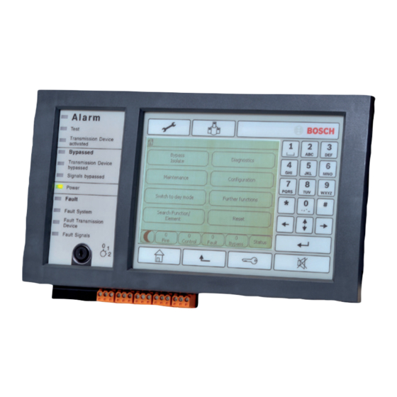
Page 21: Touch Screen
Main processor is malfunctioning Fault Yellow Transmission device is Transmission malfunctioning Device Fault Signals Yellow External signaling device malfunctioning Yellow Panel or any panel in the network is in daymode Touch screen Bosch Sicherheitssysteme GmbH User Guide 2017.09 | 7.0 | F.01U.258.929... - Page 22 To select a main menu, touch the corresponding menu field on the touch screen. In All functions at a glance, page 12, there is an overview of all main menus with their respective submenus. 2017.09 | 7.0 | F.01U.258.929 User Guide Bosch Sicherheitssysteme GmbH...
-
Page 23: Display Support Information
Display support information To display the address of the company providing the support, please press: Notice! Information concerning support is only displayed if the information has already been entered in FSP‑5000‑RPS. Bosch Sicherheitssysteme GmbH User Guide 2017.09 | 7.0 | F.01U.258.929... -
Page 24: Operating Principle
Refer to Change password, page 91 for information on how to set up your own password. The standby display is shown. As long as an operator is logged in, the key icon will be displayed on the info bar. 2017.09 | 7.0 | F.01U.258.929 User Guide Bosch Sicherheitssysteme GmbH... -
Page 25: Logging Out
To retrieve the personalized menu log into the panel: Press the “key” key and enter your user lD and password. To change back from the personalized menu to the common start menu press the “home” key. Bosch Sicherheitssysteme GmbH User Guide 2017.09 | 7.0 | F.01U.258.929... -
Page 26: Selecting The Menu
Example: To display a list of all existing detectors sorted by description in the Bypass submenu, select the following in the start menu: 2017.09 | 7.0 | F.01U.258.929 User Guide Bosch Sicherheitssysteme GmbH... -
Page 27: Scrolling Through Lists
List field State of list Meaning field normal Element in normal state TEXT marked Selected element TEXT Mode assigned The element was assigned the bypassed mode; TEXT seeAssigning mode, page 28. Bosch Sicherheitssysteme GmbH User Guide 2017.09 | 7.0 | F.01U.258.929... -
Page 28: Selecting Element/Function
The sand glass icon indicates an entry that is still being processed by the system. Notice! In the Bypass submenu, the function fields have an additional selection option; see Displaying and un-bypassing bypassed element groups, page 57. 2017.09 | 7.0 | F.01U.258.929 User Guide Bosch Sicherheitssysteme GmbH... -
Page 29: Search Function/Element
"Enter" key. The list field of the element you are searching for is then displayed at the beginning of the list. Entering numbers and text Character .,-_0 ABCabc2 Bosch Sicherheitssysteme GmbH User Guide 2017.09 | 7.0 | F.01U.258.929... - Page 30 4 on the info bar is marked. The number 4 is displayed on the search window. Quick entry: In order to enter text quickly, press the "Enter" key after entering each letter. 2017.09 | 7.0 | F.01U.258.929 User Guide Bosch Sicherheitssysteme GmbH...
-
Page 31: Changing An Entry
To quit standby mode, touch any part of the touch screen. 5.13 Logical and physical addressing When addressing elements, there is a distinction between logical and physical addressing: Bosch Sicherheitssysteme GmbH User Guide 2017.09 | 7.0 | F.01U.258.929... - Page 32 | Operating principle Panel Controller Physical Elements Modules Loop Element Numbers Logical Elements Zone Element Numbers Examples: Element with physical addressing: 5.1 - 4 Element with logical addressing: 3 - 4 2017.09 | 7.0 | F.01U.258.929 User Guide Bosch Sicherheitssysteme GmbH...
-
Page 33: Networked Panels
ID and group ID, which are assigned using the FSP-5000-RPS programming software. If, for example, a fault in a detector with network address 1 - 4 is displayed, this means: – Group ID = 1 – Node ID = 4 Bosch Sicherheitssysteme GmbH User Guide 2017.09 | 7.0 | F.01U.258.929... -
Page 34: Establishing A Remote Connection With A Networked Panel
Isolating and restricted connection All functions can be operated via an isolating connection, with the exception of the following functions: – LED, foil, display and display touch test – Adjust touch screen 2017.09 | 7.0 | F.01U.258.929 User Guide Bosch Sicherheitssysteme GmbH... - Page 35 Select the isolated panels you require from the list. Select OK and confirm the subsequent query with OK. The isolation of the panel is lifted and a restricted connection is established. Bosch Sicherheitssysteme GmbH User Guide 2017.09 | 7.0 | F.01U.258.929...
-
Page 36: Networking Via Ethernet
Select OK to confirm application of the Ethernet settings (Use Ethernet settings) or Cancel to exit the screen without activating the Ethernet settings. Notice! Changes to Ethernet settings take effect after restarting the panel. 2017.09 | 7.0 | F.01U.258.929 User Guide Bosch Sicherheitssysteme GmbH... -
Page 37: Ethernet Redundancy
Select OK to apply the changes to the RSTP parameters or Cancel to discard the changes. Notice! Changes to RSTP parameters take effect after restarting the panel. Bosch Sicherheitssysteme GmbH User Guide 2017.09 | 7.0 | F.01U.258.929... -
Page 38: Diagnostics
RSTP, the RSTP parameters of the RSTP panel and those of the root bridge are displayed. Further information can be found in Network services, page 64. 2017.09 | 7.0 | F.01U.258.929 User Guide Bosch Sicherheitssysteme GmbH... -
Page 39: Remote Keypad
The following functions cannot be executed from the remote keypad via a remote connection: – LED, foil, display and display touch test – Adjust touch screen Bosch Sicherheitssysteme GmbH User Guide 2017.09 | 7.0 | F.01U.258.929... -
Page 40: Alarm
These strategies are principally used in fire detectors but can also be assigned to any other detector, depending on how it is configured. The alarm delays that can be shown in the panel controller display are explained below. 2017.09 | 7.0 | F.01U.258.929 User Guide Bosch Sicherheitssysteme GmbH... -
Page 41: Day And Night Mode
LED display lights up red: Depending on the configuration, a detector in night mode triggers a pre-alarm if intermediate alarm storage is used as an alarm delay for this detector. Bosch Sicherheitssysteme GmbH User Guide 2017.09 | 7.0 | F.01U.258.929... -
Page 42: Alarm Message To The Panel
List fields without distinction: acknowledged alarm messages Logical Zones Notice! A maximum of four alarm messages can be displayed on the display simultaneously. Only fields that can be operated are displayed (e.g. Acknowledge and Reset). 2017.09 | 7.0 | F.01U.258.929 User Guide Bosch Sicherheitssysteme GmbH... -
Page 43: Sequence Of The Alarm Messages
Depending on the configuration, the message type may be defined more specifically, e.g. Fire PAS for a fire alarm with alarm verification. Address of logical zone 00005: the fifth logical zone triggered the first fire alarm. Bosch Sicherheitssysteme GmbH User Guide 2017.09 | 7.0 | F.01U.258.929... -
Page 44: The Newest Message
If the detector number, in this case (004), is not displayed, this is the alarm message for the logical zone. Notice! Depending on the configuration of the system, either the logical or physical address of the detector is displayed. 2017.09 | 7.0 | F.01U.258.929 User Guide Bosch Sicherheitssysteme GmbH... -
Page 45: Displaying Additional Information
Date and time of the message – Physical and logical addressing of the detector – Only for LSN detectors: specification of the detector type – Action text (depending on the configuration) Bosch Sicherheitssysteme GmbH User Guide 2017.09 | 7.0 | F.01U.258.929... -
Page 46: Fire Alarm
If Go to Acknowledge is displayed, select this field in order to display the messages that have not yet been acknowledged. 10.3 Switching off internal buzzer Press the following key to temporarily switch off the internal buzzer: 2017.09 | 7.0 | F.01U.258.929 User Guide Bosch Sicherheitssysteme GmbH... -
Page 47: Switching External Signaling Devices On And Off
Caution! If another fire alarm is reported during the time to investigate, all alarm messages are transmitted to the fire department. The time to investigate is canceled. Bosch Sicherheitssysteme GmbH User Guide 2017.09 | 7.0 | F.01U.258.929... -
Page 48: Starting Time To Investigate
If, during the check, a real fire alarm is detected, then this alarm to the panel must be manually forwarded to external stations such as the fire department. Alternatively, a manual call point can be triggered at the location. 2017.09 | 7.0 | F.01U.258.929 User Guide Bosch Sicherheitssysteme GmbH... -
Page 49: Resetting Alarm Message
If an element cannot be reset, it will continue to be displayed in the list. After the successful resetting of all elements, the standby display is displayed. 10.8 Bypassing detectors To bypass a detector that has triggered an alarm: Bosch Sicherheitssysteme GmbH User Guide 2017.09 | 7.0 | F.01U.258.929... - Page 50 Select the alarm message you require. Select Bypass. Notice! The system does not transmit any information as to whether it was possible to bypass the selected element. To monitor the operation, please check the element. 2017.09 | 7.0 | F.01U.258.929 User Guide Bosch Sicherheitssysteme GmbH...
-
Page 51: Fault Message
Acknowledging an individual message: First select the message and then press Acknowledge. Element groups Logically addressed logical zones are displayed in a list. List fields with black background indicate unacknowledged fault messages. List fields without distinction indicate acknowledged fault messages. Bosch Sicherheitssysteme GmbH User Guide 2017.09 | 7.0 | F.01U.258.929... -
Page 52: Sequence Of The Trouble Messages
001: The first and oldest fault message received. Installation location of the Office 1 logical zone Notice! Depending on the configuration of the system, either the logical or physical address of the element is displayed. 2017.09 | 7.0 | F.01U.258.929 User Guide Bosch Sicherheitssysteme GmbH... -
Page 53: The Newest Message
To display more information about an alarm message, see Displaying additional information, page 53. 11.2.7 Displaying additional information To display further information about the individual elements, select the fault message you require. Bosch Sicherheitssysteme GmbH User Guide 2017.09 | 7.0 | F.01U.258.929... -
Page 54: Signals
If a list field is marked with an "R", the process of resetting is not yet complete for this element. TEXT If an element cannot be reset, it will continue to be displayed in the list. 2017.09 | 7.0 | F.01U.258.929 User Guide Bosch Sicherheitssysteme GmbH... -
Page 55: Isolating An Element
Select the fault message you require. Select Block. Caution! The system does not transmit any information as to whether it was possible to isolate the selected element. To monitor the operation, check the element. Bosch Sicherheitssysteme GmbH User Guide 2017.09 | 7.0 | F.01U.258.929... -
Page 56: Bypass
A list of the detectors is displayed. Refer to Scrolling through lists, page 27 for information on how to scroll forward and backward through the list. Select the required list fields. The list fields are marked. 2017.09 | 7.0 | F.01U.258.929 User Guide Bosch Sicherheitssysteme GmbH... -
Page 57: Displaying And Un-Bypassing Bypassed Element Groups
Select the element category you require, e.g. Detector . A list of all bypassed detectors is displayed: To un-bypass bypassed elements: Select the element you require. Select Un- bypass. The element is un-bypassed. Bosch Sicherheitssysteme GmbH User Guide 2017.09 | 7.0 | F.01U.258.929... -
Page 58: Via The Status Bar
To remove the bypass from the buzzer, select Unbypass buzzer in step 4. Notice! If you switch the internal buzzer off permanently, no acoustic signal will sound on the panel in the event of an alarm or fault! 2017.09 | 7.0 | F.01U.258.929 User Guide Bosch Sicherheitssysteme GmbH... -
Page 59: Isolate
Displaying list of all isolated elements There are two ways to display a list of all isolated elements: – Using the menu, page 60 – Via the status bar, page 60 Bosch Sicherheitssysteme GmbH User Guide 2017.09 | 7.0 | F.01U.258.929... -
Page 60: Using The Menu
Select the list field you require, e.g. Detector . A list of all isolated elements is displayed. To de-isolate isolated elements: Select the element you require. Select Un- block. The element is de-isolated. 2017.09 | 7.0 | F.01U.258.929 User Guide Bosch Sicherheitssysteme GmbH... -
Page 61: Diagnostics
The other two possibilities deviate only slightly from this. Example: Select Info for element group. A list of the elements of the selected LSN module is displayed. Bosch Sicherheitssysteme GmbH User Guide 2017.09 | 7.0 | F.01U.258.929... -
Page 62: Modules
Select Refresh to update data if necessary. 14.4.2 Display Five different functions are offered: – LED test: Test the LED display. – Key test: Test the operativeness of the membrane keypad. 2017.09 | 7.0 | F.01U.258.929 User Guide Bosch Sicherheitssysteme GmbH... - Page 63 Press the "back" function key to end the operation. Adjust touch screen (Calibration) To adjust the press precision when touching the touch screen: In the start menu, select Diagnostics Hardware Display Bosch Sicherheitssysteme GmbH User Guide 2017.09 | 7.0 | F.01U.258.929...
-
Page 64: Serial Interface
The LEDs are activated for the duration of approx. five seconds. Notice! The numbers before the module names indicate the slot of the module on the panel. 14.7 Network services 14.7.1 Routing table To display routing information: 2017.09 | 7.0 | F.01U.258.929 User Guide Bosch Sicherheitssysteme GmbH... -
Page 65: Consistency Check
RPS ("configured"). 14.7.3 Ethernet ports To display a table listing the various parameters and the status of the two Ethernet ports: In the start menu, select Diagnostics Network services Bosch Sicherheitssysteme GmbH User Guide 2017.09 | 7.0 | F.01U.258.929... -
Page 66: Send Ping Command
– Root bridge/ local bridge: – Priority – MAC address – Hello time – Max. age – Forward delay – Ethernet 1/Ethernet 2 port: – Port role – Port status 2017.09 | 7.0 | F.01U.258.929 User Guide Bosch Sicherheitssysteme GmbH... -
Page 67: Remote Services
If you enable the Remote Alert service, an FPA-5000/FPA-1200 system pushes relevant status information and events (e.g. alarms or fault messages) to the Bosch Remote Portal. In case of an unexpected event, an alert can e.g. be delivered to a technician in form of SMS or Email (if configured in the Remote Portal) so that relevant actions can be started at once. -
Page 68: Voice Alarm Systems
– Connection status: Shows whether an IP connection to the VAS over IP exists. – Status of VAS over IP: In case of trouble please check the VAS over IP. 2017.09 | 7.0 | F.01U.258.929 User Guide Bosch Sicherheitssysteme GmbH... - Page 69 Port of VAS over IP: VAS over IP port number. The default value is 9401. To check the availability of the VAS over IP in the network, choose Send ping command to send a ping request to the VAS over IP IP address. Bosch Sicherheitssysteme GmbH User Guide 2017.09 | 7.0 | F.01U.258.929...
-
Page 70: Maintenance
Select a category or Select by number and enter the number of the element into the search screen; see also Search Function/Element, page 29 Select the required list fields. The list fields are marked. 2017.09 | 7.0 | F.01U.258.929 User Guide Bosch Sicherheitssysteme GmbH... -
Page 71: Activate Transmission Device
When the 15 minutes are up, the panel emits a brief signal tone and the start menu is displayed. 15.6 Change device on V.24 Interface On the V.24 interface, other devices can be optionally assigned in addition to a permanently assigned device. Bosch Sicherheitssysteme GmbH User Guide 2017.09 | 7.0 | F.01U.258.929... -
Page 72: Bypassing/Un-Bypassing Buzzer
To remove the bypass from the buzzer, select Unbypass buzzer in step 2. Notice! If you switch the internal buzzer off permanently, no acoustic signal will sound on the panel in the event of an alarm or fault! 2017.09 | 7.0 | F.01U.258.929 User Guide Bosch Sicherheitssysteme GmbH... -
Page 73: Maintenance - Walktest
Show / Change: Delete all elements in the selected walk test group and delete individual elements. – Add: Display all elements that have not yet been assigned to a walk test group, and add individual elements. – Cancel: Cancel the operation. Bosch Sicherheitssysteme GmbH User Guide 2017.09 | 7.0 | F.01U.258.929... - Page 74 The display changes. Various element categories containing elements which have not been assigned to any walktest group yet are displayed. Select the element category you require. Select one or more list fields. The list fields are marked. 2017.09 | 7.0 | F.01U.258.929 User Guide Bosch Sicherheitssysteme GmbH...
-
Page 75: Starting And Ending Walktest
To end the walktest for this walktest group: Mark the selected walktest group. Select Off. 16.3 Ending walktest for all elements To end the walktest for all walktest groups and elements: Bosch Sicherheitssysteme GmbH User Guide 2017.09 | 7.0 | F.01U.258.929... -
Page 76: Displaying Tested Or Untested Elements
– Select Overwrite walktest group to replace the elements in the selected walk test group with the tested elements from the current walk test. 2017.09 | 7.0 | F.01U.258.929 User Guide Bosch Sicherheitssysteme GmbH... -
Page 77: Maintenance - History Log
A list of all fault messages is displayed. The events are sorted in ascending order by date and time. The fault messages are numbered chronologically. The leading number indicates the sequence in which the fault messages were received. Bosch Sicherheitssysteme GmbH User Guide 2017.09 | 7.0 | F.01U.258.929... -
Page 78: Change Filter
All events with the selected date are displayed in the list. Print Print the complete displayed list or only a part of it. Exit End the entry and switch to the menu overview for the Maintenance menu. 2017.09 | 7.0 | F.01U.258.929 User Guide Bosch Sicherheitssysteme GmbH... -
Page 79: Printing Out Data
A list of the printers that can be selected is displayed. Select a printer. Select Print. The list is printed. Event numbers To display the event numbers again: Select Show event numbers. To exit the display, press the "Back" key. Bosch Sicherheitssysteme GmbH User Guide 2017.09 | 7.0 | F.01U.258.929... -
Page 80: Day And Night Mode
Depending on the mode to which the panel is switched, Switch to day mode or Switch to night mode is displayed in the start menu. The panel is in night mode: Select Switch to day mode to switch to day mode: 2017.09 | 7.0 | F.01U.258.929 User Guide Bosch Sicherheitssysteme GmbH... -
Page 81: Showing Details
The set back time can be changed in day or night mode. To change the time for resetting in night mode: On the status bar, select In the start menu, select Switch to day mode. Select Change time. Bosch Sicherheitssysteme GmbH User Guide 2017.09 | 7.0 | F.01U.258.929... - Page 82 Enter the numbers you require. Refer to Entering numbers and text, page 29 for information on how to enter numbers. Select OK to confirm the entry or Cancel to cancel the operation. 2017.09 | 7.0 | F.01U.258.929 User Guide Bosch Sicherheitssysteme GmbH...
-
Page 83: Configuration
Add: Display all elements that have not yet been assigned to an input group, and add individual elements. – Cancel: Cancel the operation. To change the name of the input group, see Change name, page 85. Bosch Sicherheitssysteme GmbH User Guide 2017.09 | 7.0 | F.01U.258.929... - Page 84 Select the element category you require. Select one or more list fields. The list fields are marked. Select Add. The selected element is added to the selected walktest group. 2017.09 | 7.0 | F.01U.258.929 User Guide Bosch Sicherheitssysteme GmbH...
-
Page 85: Change Name
In the start menu, select Configuration Detector sensitivity Various lists are offered. Refer to Scrolling through lists, page 27 for information on how to scroll forward and backward through a list. Bosch Sicherheitssysteme GmbH User Guide 2017.09 | 7.0 | F.01U.258.929... -
Page 86: Operator
Change universal password In the start menu, select Configuration Operator Change universal password Depending on the access level for which the password is to be changed, select the list field you require. 2017.09 | 7.0 | F.01U.258.929 User Guide Bosch Sicherheitssysteme GmbH... -
Page 87: Set Default Password
Remote Services is required. For detailed instructions on setting up a connection to the Remote Portal please refer to the Networking Guide. To configure a connection to the Bosch Remote Portal in order to enable Remote Services perform the following steps:... -
Page 88: Overview
Configuration and additional information on this – Date – Configuration version (Config. version) – Number – Name – IP address – Scope – Country – Time zone – Menu name 2017.09 | 7.0 | F.01U.258.929 User Guide Bosch Sicherheitssysteme GmbH... -
Page 89: Further Functions
One of the following two options is offered: – Entering a master password that is valid indefinitely. This password cannot be changed and is available from the relevant Bosch branch on request. – Entering a master password that is valid for a specified period of time. -
Page 90: Enter The 24-Hour Master Password
In the start menu, select Further functions – Remote Services – Select Block Remote Maintenance. The transmission of data to the Remote Portal is stopped until the next restart of the panel controller. 2017.09 | 7.0 | F.01U.258.929 User Guide Bosch Sicherheitssysteme GmbH... -
Page 91: Change Password
To start a drill: In the start menu, select Further functions Drill Confirm Start drill with OK The drill is started. To end the drill, select Stop drill. Bosch Sicherheitssysteme GmbH User Guide 2017.09 | 7.0 | F.01U.258.929... -
Page 92: Alarm Counters
Confirm the message "Attention: Counter will be reset" with OK to reset the alarm counter to 0 or select Cancel to cancel the operation. Notice! In order to reset alarm counters, you need authorization level 4. 2017.09 | 7.0 | F.01U.258.929 User Guide Bosch Sicherheitssysteme GmbH... -
Page 93: Reset
If a list field is marked with an R, the process of resetting is not yet complete for this element: TEXT If an element cannot be reset, it will continue to be displayed in the list. After the elements have been reset, the standby display is displayed. Bosch Sicherheitssysteme GmbH User Guide 2017.09 | 7.0 | F.01U.258.929... -
Page 94: Search Function/Element
– the message types (e.g. fault, alarm etc.) that can be assigned to this element. – the mode (e.g. bypassed, reset etc.) that the selected element is in. 2017.09 | 7.0 | F.01U.258.929 User Guide Bosch Sicherheitssysteme GmbH... -
Page 95: Index
Changing time for resetting to night mode 81 Fault message, resetting 54 Checking access authorization 25 Fault message, sequence 52 Configuration version 88 Fault, element group 51 Consistency check 65 Fault, signals 54 Bosch Sicherheitssysteme GmbH User Guide 2017.09 | 7.0 | F.01U.258.929... - Page 96 93 Lists, scrolling 27 Resetting, zone 93 Logging in 24 Restricted connection 34 Logging out 25 Routing table 64 Logical addressing 31 RSTP settings 37 MAC Address 64 Scope 88 2017.09 | 7.0 | F.01U.258.929 User Guide Bosch Sicherheitssysteme GmbH...
- Page 97 VAS over IP 68 Walktest Group 85 Walktest groups 73 Walktest groups, adding elements 73 Walktest groups, deleting elements 73 Walktest, displaying tested elements 76 Walktest, displaying untested elements 76 Water 40 Bosch Sicherheitssysteme GmbH User Guide 2017.09 | 7.0 | F.01U.258.929...
- Page 98 | Index Panel Controller 2017.09 | 7.0 | F.01U.258.929 User Guide Bosch Sicherheitssysteme GmbH...
- Page 100 Bosch Sicherheitssysteme GmbH Robert-Bosch-Ring 5 85630 Grasbrunn Germany www.boschsecurity.com © Bosch Sicherheitssysteme GmbH, 2017...