Bosch B9512G Installation Manual
Hide thumbs
Also See for B9512G:
- Program entry manual (284 pages) ,
- Owner's manual (228 pages) ,
- Installation and system reference manual (186 pages)

Related Manuals for Bosch B9512G


Summary of Contents for Bosch B9512G
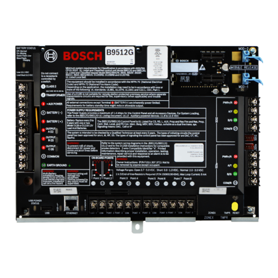
- Page 1 Control Panels B9512G/B8512G/B6512/B5512/B4512/B3512 (B9512G‑E/ B8512G‑E/B5512E/B4512E/B3512E) ULC Installation Manual...
- Page 3 CEC (Canadian Electrical Code). Control panels Use this guide with the following control panel models (unless otherwise stated) and the model’s installation guide: – B9512G/B9512G-E v3.02.006 and higher – B8512G/B8512G-E v3.02.006 and higher – B6512 –...
- Page 4 Install with ULC Listed devices where applicable. Wiring Use unshielded cable only. Copyright This document is the intellectual property of Bosch Security Systems, Inc. and is protected by copyright. All rights reserved. Trademarks All hardware and software product names used in this document are likely to be registered trademarks and must be treated accordingly.
- Page 5 Battery size B6512/B5512/B4512/B3512: 1 x 12 V/7 Ah, 1 x 12 V/18 Ah, 2x 12 V/7 Ah B9512G/B8512G: 2x 12 V/18 Ah Entry delay ≤ 45 sec ≤ 45 ≤ 45 Exit delay ≤ 45 sec ≤...
- Page 6 D6100IPv6 Medium communication channels, refer to the High figures in Fire monitoring communication systems wiring diagrams, page 18. *Test the transmission on each communication channel every 24 hours. 2019.06 | 02 | F.01U.321.698 Bosch Security Systems B.V.
- Page 7 “denial of service” attacks. For using public switched and wireless data networks, communication channels must be facilitated such that the communicator will restrict unauthorized access which could otherwise compromise security. Bosch Security Systems B.V. 2019.06 | 02 | F.01U.321.698...
- Page 8 This might require duplicate protection armed by each area. Access to this protected area, without causing an alarm, requires that all areas are disarmed. 2019.06 | 02 | F.01U.321.698 Bosch Security Systems B.V.
- Page 9 An X in a column indicates the accessory is compatible with the standard. Model Desc- number ription Keypads B915/ Basic B915I* B920* 2-line B921C* Capacit B925F* Fire/ Burg B926F* Fire Bosch Security Systems B.V. 2019.06 | 02 | F.01U.321.698...
- Page 10 Battery Suitable for use on approved applications. (12.0 VDC, 7 D1218 Battery Suitable for use on approved applications. (12 V, 18 Ah) D1640- Transfo Suitable for use on approved applications in Canada. rmer 2019.06 | 02 | F.01U.321.698 Bosch Security Systems B.V.
- Page 11 Suitable for use on approved applications in Canada. TR1822- rmer Enclosures B10*** Mediu Small B8103** Large, white D8103** Large, grey D8109** Fire D8108A* Attack resista Expansion modules B208 Octo- input B299 POPEX X B308 Octo- output Bosch Security Systems B.V. 2019.06 | 02 | F.01U.321.698...
- Page 12 B600 ZONEX X D125B Dual initiatin D129 Dual initiatin D192G D8125 POPEX X D8125M Multipl D8128D OctoP OPIT D8129 Octo- relay D8130 Door release D9127U POPIT Communicators B426 Ethern 2019.06 | 02 | F.01U.321.698 Bosch Security Systems B.V.
- Page 13 D132A Smoke reversi D161 Phone Suitable for use on approved applications. switche D162 Phone Suitable for use on approved applications. cord ICP- SDI-911 splitter ICP- Tamper X EZTS Door control (Access) Bosch Security Systems B.V. 2019.06 | 02 | F.01U.321.698...
- Page 14 **Combination fire and burg systems using SDI devices might require an ICP-SDI-9114 to separate fire and intrusion devices onto separate circuits. ***In ULC-S559, the enclosure is certified for use with B9512G/B8512G only. ULC listed for Proprietary Burglary and Residential Fire only.
- Page 15 B3512 control panels must have keypads installed in the same room within 18 m and in metallic conduit. B9512G and B8512G control panels are not required to have keypad installed in the same room within 18 m. For B6512/B5512/B4512/B3512 control panels, refer to the D135A Installation Guide (P/N: 4998122704) for instructions.
-
Page 16: Control Panel
EOL supervised inputs Fire Alarm Point 1 Fire Trouble Point 2 Fire Supervisory Point 3 Figure 1.1: Fire alarm control unit dry contact outputs to control panel points 1, 2, and 3 2019.06 | 02 | F.01U.321.698 Bosch Security Systems B.V. - Page 17 Figure 1.4: Double EOL input for one Form C contact Callout ᅳ Description 1 ᅳ Point sensor loop terminals 2 ᅳ Normally closed device (contact) 3 ᅳ EOL Resistor – 1.0 kΩ (2.0 kΩ and No EOL optional) at device Bosch Security Systems B.V. 2019.06 | 02 | F.01U.321.698...
- Page 18 Separate paths throughout the protected premises and through any common carrier or third party communications network to the fire signal receiving center shall be provided for each communication channel. 2019.06 | 02 | F.01U.321.698 Bosch Security Systems B.V.
- Page 19 On-board IP modem Listed enclosure Keypad (models B915/B915I/B920) Figure 1.6: Control panel with on-board IP NOTES: The B9512G-E/B8512G-E/B5512E/B4512E/B3512E control panels do not include on-board IP. Systems with single communication channels must be active. Bosch Security Systems B.V. 2019.06 | 02 | F.01U.321.698...
- Page 20 B426 Listed enclosure Keypad (models B915/B915I/B920) Figure 1.7: Control panel with a B426 module NOTES: The B9512G-E/B8512G-E/B5512E/B4512E/B3512E control panels require a B426 for IP. Systems with single communication channels must be active. PSTN/IP communication system (on-board IP) Control panel Fire alarm...
- Page 21 B426 modem Listed enclosure Keypad (models B915/B915I/B920) Figure 1.9: Control panel with a B426 module and a B430 (PSTN) module NOTES: The B9512G-E/B8512G-E/B5512E/B4512E/B3512E control panels require a B426 for IP. Cellular communication system Control panel Fire alarm (models control unit B9512G/B8512G/...
- Page 22 B9512G/B8512G/ B6512/B5512/ Outputs B4512/B3512) Inputs Fire Supervisory Antenna Trouble B44x B430 PSTN Listed enclosure Keypad (models B915/B915I/B920) Figure 1.12: Control panel with a compatible cellular module and a 430 (PSTN) module 2019.06 | 02 | F.01U.321.698 Bosch Security Systems B.V.
- Page 23 B6512/B5512/ Outputs B4512/B3512) Fire Supervisory Trouble B430 Inputs PTSN Bus connection, supervised B44x Antenna Listed enclosure Keypad (models B915/B915I/B920) Figure 1.13: Control panel with a B44x module and a B430 (PSTN) module Bosch Security Systems B.V. 2019.06 | 02 | F.01U.321.698...
- Page 24 B9512G/B8512G UL Listing Document, ULLD. Auxiliary powered devices: 11.8 to 12.5 VDC Battery: Replace every 3 to The B9512G/B8512G Control Panel is UL Listed For CS, RS, L, AUX, Prop and Res Fire and Res, Prop, BATTERY ( + ) 5 years with one or two Cent.
- Page 25 B426 module, supervised). AC input is required (not shown). 1.3.3 B Series sounder wiring diagram For B6512/B5512/B4512/B3512 control panels, use a ULC Listed, 12 VDC (100 mA maximum) sounder connected to output 1. Bosch Security Systems B.V. 2019.06 | 02 | F.01U.321.698...
- Page 26 [3] keys for 3 seconds. The segment test lights the LEDs and the display. NOTE: During the segment test, the B915/B915I reports a missing trouble. Programming Complete the programming steps in this section for ULC compliance. 2019.06 | 02 | F.01U.321.698 Bosch Security Systems B.V.
- Page 27 Set Point Type / Response / Circuit Style > Circuit Style to: Single EOL (1KΩ) or Single EOL (2KΩ). Set Response to: 3. Point Profile 4 Set Point Profile Text (First Language) to: Fire Panel Alarm. Set Point Type / Response / Circuit Style > Point Type to: Fire Point. Bosch Security Systems B.V. 2019.06 | 02 | F.01U.321.698...
- Page 28 If you set Point Type / Response / Circuit Style > Circuit Style to Single EOL (1KΩ) or Single EOL (2KΩ), set Response to: 9. If you set Point Type / Response / Circuit Style > Circuit Style to Dual EOL, set Response to: 2. Figure 1.18: Point Profiles 2019.06 | 02 | F.01U.321.698 Bosch Security Systems B.V.
- Page 29 Set Point Assignments > Profile to: 1 - Fire Panel Trouble Point 3 Set Point Assignments > Text to: Fire Panel Supervisory. Set Point Assignments > Profile to: 6 - Fire Panel Supervisory Figure 1.20: Fire Panel Supervisory Bosch Security Systems B.V. 2019.06 | 02 | F.01U.321.698...
- Page 30 Custom settings. Figure 1.21: Report Routing PANEL WIDE PARAMETERS > Report Routing > Diagnostic Reports For the Route Group 4 column, set SDI2 Device Failure to Yes. Set the remaining reports to No. 2019.06 | 02 | F.01U.321.698 Bosch Security Systems B.V.
- Page 31 In the Destination 4 column, set Network Address to: 0.1.1.1 (this address is intentionally not a real address on the network). Set the Poll Rate to 0. Set the ACK Wait Time (sec.) to 5. Bosch Security Systems B.V. 2019.06 | 02 | F.01U.321.698...
- Page 32 Set Custom Function 128 > Function 1 to: Trouble Silence (set Parameter 1 to: Area 1). Set Custom Function 128 > Function 2 to: Alarm Silence (set Parameter 1 to: Area 1). 2019.06 | 02 | F.01U.321.698 Bosch Security Systems B.V.
- Page 33 Set Panel Wide Outputs > Summary Fire Trouble to: 10. Set Panel Wide Outputs > Summary Supervisory Fire to: 19. Figure 1.27: Panel Wide Outputs POINTS > Point Profiles (Point Indexes) Configure Point Profile 20 as shown below. Bosch Security Systems B.V. 2019.06 | 02 | F.01U.321.698...
- Page 34 Set Point Assignments > Profile to: 20 - CF: Silence Point 19 Set Point Assignments > Source to: Ouput. Set Point Assignments > Text to: Fire Supervisory Active. Set Point Assignments > Profile to: 20 - CF: Silence 2019.06 | 02 | F.01U.321.698 Bosch Security Systems B.V.
- Page 35 Control Panels ULC Installation Guide | en Figure 1.29: Point Assignments Bosch Security Systems B.V. 2019.06 | 02 | F.01U.321.698...
- Page 36 | ULC Installation Guide Control Panels 2019.06 | 02 | F.01U.321.698 Bosch Security Systems B.V.
- Page 37 Control Panels ULC Installation Guide | Bosch Security Systems B.V. 2019.06 | 02 | F.01U.321.698...
- Page 38 | ULC Installation Guide Control Panels 2019.06 | 02 | F.01U.321.698 Bosch Security Systems B.V.
- Page 40 Bosch Security Systems B.V. Torenallee 49 5617 BA Eindhoven Netherlands www.boschsecurity.com © Bosch Security Systems B.V., 2019...