Table of Contents
Advertisement
Quick Links
Instructions - Parts
™
PGM
Precision Gear Metering
For metering and dispensing ambient or high-temperature, high-viscosity
single-component materials. For professional use only.
Not approved for use in European explosive atmosphere locations.
2500 psi (17.2 MPa, 172 bar) Maximum Working Outlet Pressure
1500 psi (10.3 MPa, 103 bar) Maximum Working Inlet Pressure
See Technical Specifications on page 102 for temperature ranges
See page 4 for model information.
Important Safety Instructions
Read all warnings and instructions in this
manual. Save these instructions.
3A5185B
EN
Advertisement
Table of Contents
Troubleshooting

Related Manuals for Graco PGM


Summary of Contents for Graco PGM
- Page 1 Instructions - Parts ™ 3A5185B Precision Gear Metering For metering and dispensing ambient or high-temperature, high-viscosity single-component materials. For professional use only. Not approved for use in European explosive atmosphere locations. 2500 psi (17.2 MPa, 172 bar) Maximum Working Outlet Pressure 1500 psi (10.3 MPa, 103 bar) Maximum Working Inlet Pressure See Technical Specifications on page 102 for temperature ranges See page 4 for model information.
-
Page 2: Table Of Contents
Install Cable Assemblies ....17 PGM-6 Drive Kit ......61 System Setup . -
Page 3: Related Manuals
Appendix B - I/O ......98 Using the PGM I/O ..... . 98 Appendix C - Theory of Operation . -
Page 4: Models
Models Models NOTE: This manual covers a series change to the PGM system. For systems built prior to 2016, refer to manual 3A0260. Check the identification (ID) plate for the 6-digit part number of the fluid metering system. Use the following matrix to define the construction of the system, based on the six digits. -
Page 5: Remote Dispense Valves
Models Remote Dispense Valves Part Description 124267 Seal Housing, 6 cc Part Description 24E826 Gear Shaft Repair Kit, 6 cc 243694 Heated Dispense Valve 24E827 Seal Shaft Repair Kit, 6 cc 244951 EnDure Valve, Heated, 124266 Pump Seal Housing, 20 cc 1/2 in. -
Page 6: Warnings
Warnings Warnings The following warnings are for the setup, use, grounding, maintenance, and repair of this equipment. The exclama- tion point symbol alerts you to a general warning and the hazard symbols refer to procedure-specific risks. When these symbols appear in the body of this manual or on warning labels, refer back to these Warnings. Product-specific hazard symbols and warnings not covered in this section may appear throughout the body of this manual where applicable. - Page 7 Warnings WARNING FIRE AND EXPLOSION HAZARD Flammable fumes, such as solvent and paint fumes, in work area can ignite or explode. Paint or solvent flowing through the equipment can cause static sparking. To help prevent fire and explosion: • Use equipment only in well-ventilated area. •...
-
Page 8: Overview
Overview Overview System Configurations Typical Heated System Installation Air Supply Power Drop Site . 1: Typical Heated System Installation Key: AA *Control Center (User Interface) AG Heated Fluid Supply System AB *Gear Meter Assembly AH Fluid Supply Hose AC Applicator/Dispense Valve† AJ Heat Control AD Automation Robot AK Automation Controller... - Page 9 Overview Typical Ambient System Installation Air Supply Power Drop Site . 2: Typical Ambient System Installation Key: *Control Center (User Interface) *Gear Meter Cables *Gear Meter Assembly G Fluid Supply System *Applicator/Dispense Valve Fluid Supply Hose Automation Robot Automation Controller Automation Interface Cable†...
-
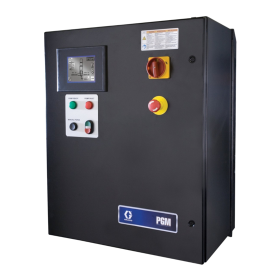
Page 10: Component Identification
Overview Component Identification Key: Gear Meter Emergency Stop System Controls Box Pump Fault Indicator Light User-Interface Touch Display Control Power On/Off buttons External Control Interface 10 Pump Ready Light Connections 11 Manual Purge Button Power Input 12 Dispense Valve Main Power Switch 3A5185B... -
Page 11: System Overview
• Window and Door General Assembly . 4: Control Center Dimensions The PGM system provides positive displacement meter- ing for precision bead control. The control accepts auto- mation signals to provide accurate and consistent output flow. The gear meter can achieve high flow rates with high viscosity materials. -
Page 12: Installation
Installation Before Installation Overview • Have all system and component documentation The basic steps to install a PGM system are shown available during installation. below. See the separate component manuals for detailed information on supply systems and dispense • See component manuals for specific data on compo- valves. -
Page 13: Install Control Center
F . 5. Mount Control Center Assembly Measurement Ensure the following criteria are met before mounting the PGM control center: 24.0 in. (610 mm) 22.5 in. (572 mm) • Select a location for the control center that allows 30.0 in. -
Page 14: Install Gear Meter Assembly
See component manuals for specific information on • A qualified electrician must complete all ground- component requirements. Information presented ing and wiring connections. here pertains to the PGM gear meter assembly only. • For wiring, refer to F . 6. •... - Page 15 Installation 2. Mount and secure the gear meter assembly to the automation unit (or other mounting surface) with mounting plate. The mounting plate is tapped with M10 x 1.5 bolts. Maximum bolt length through plate is 0.75 in. (19 mm). See the mounting dimensions in Table 4 and F .
- Page 16 For static dissipation, use only electrically conductive plumbing in air filter assembly (234967). Plumb in air hoses or ground the applicator / dispense valves. filter assembly near air drop site (upstream of PGM). Adding an air regulator to this line will provide more Dispense Valve consistent dispense valve response times.
-
Page 17: Install Cable Assemblies
Installation Install Cable Assemblies 1. Connect servo motor power and feedback cables. 3. Connect dispense valve solenoid cable. 2. Connect pressure transducer cable. 4. Connect heat cables, if equipped, to Therm-O-Flow controller. NOTE: Models with 15 meter cables include a remote junction box to be mounted in the field. -
Page 18: System Setup
System Setup System Setup Overview System Setup The PGM system compensates for temperature, flow, or pressure fluctuations. However, if there is a hardware Configure Control Settings (page 19) change on the supply system or the dispense material is changed, the PGM system must be setup again. -
Page 19: Configure Control Settings
System Setup Configure Control Settings Configure Mode Settings Set the controls for the dispense source, how dispense Set the dispense mode (bead or shot). The bead scale commands are sent, and auto mode settings. and pre-charge are also adjustable from the Mode Set- tings screen. -
Page 20: Configure Delay Settings
System Setup Configure Delay Settings Adjust Pressure Sensors Set on and off delays (in milliseconds) for the dispense Set pressure offsets and pressure limits. valve. 1. With the system in setup mode, press to nav- 1. With the system in setup mode, press to nav- igate to the Pressure Sensor screen. -
Page 21: Configure Errors
System Setup Configure Errors Set the error type (error or deviation) that will be issued if the pressure or drive torque goes outside the set high and/or low limits. See Appendix A - User Interface Display on page 82 for information on the purpose of each error type. -
Page 22: Operation
Otherwise, follow the Standard Startup Initial Startup procedure. 1. Ensure the PGM control enclosure and all of the 2. Turn on the fluid supply pressure to the fluid inlet proper connections to and from the control enclo- block for the PGM. -
Page 23: Maintenance Mode Operation
PGM needs at its inlet. To prevent excessive static pressure at the inlet of the PGM, a dynamic regulator is recom- mended on air motor supply air. During dispense the normal pump regulator is active. During a stalled condi- tion the dynamic regulator is active. -
Page 24: Calibration
Diagram on page 82 in the Appendix A - User Interface Display section. screen. NOTE: PGM systems are calibrated at the factory. Per- form calibration after pump maintenance or during trou- bleshooting (see page 29 for troubleshooting matrix). 3. Press the Enable Calibration button 4. -
Page 25: Dispense From Maintenance Screen
Automation Control (Normal) Screen Operation 1. Navigate to the Maintenance screen. See Screen During automation control (normal operation) the PGM Navigation Diagram on page 82 in the Appendix automatically dispenses when it receives a command A - User Interface Display section. -
Page 26: Pressure Relief Procedure
Press or the Purge button on the equipment. 1. Shut off the fluid supply to the PGM inlet block. control enclosure to begin the low flow dis- pense. 2. If equipped, place a waste container beneath the fluid drain valve under the filter. - Page 27 Pressure Relief Procedure 8. If the dispense device cannot be actuated from the 9. If you suspect that a valve, hose, or dispense nozzle control center, refer to F . 16 and perform the fol- is clogged or that pressure has not been fully lowing steps to open the dispense valve and relieve relieved: fluid pressure:...
-
Page 28: Shutdown
1. Press the Stop button. See F . 17. 2. Shut off the material supply to the gear meter/meter. 3. Shut off heat to PGM. See related manuals section for Therm-O-Flow manual and Accessory Heat Con- trol. 4. For heated systems, open the dispense valve over a waste container while the system is cooling down. -
Page 29: Troubleshooting
False signal being sent to control Check inlet pressure sensor output; verify that it corresponds to zero pressure; replace sensor and/or amplifier Leak at PGM drive shaft Replace drive shaft seals No Outlet Pressure Dispense motor not rotating Refer to Error code section of the manual;... -
Page 30: Dispense Valves
Troubleshooting Dispense pattern too light Supply pressure too low Verify inlet pressure needed for flow rate Flow rate too high for application Perform dispense weight verifica- tion, see Calibration procedure on page 24; Lower flow rate and repeat Measured flow does not match Supply pressure too low Verify inlet pressure needed for flow command... -
Page 31: Errors
Errors Errors View Errors Clear Errors and Reset Control Unit Errors can be viewed from the Home screen or from the Alarm View screen. Access the Alarm View screen From the Alarm View screen, perform the following There are three levels of errors: alarms, deviations, and steps to clear an error before restarting the control unit: advisories. -
Page 32: Error Codes And Troubleshooting
Errors Error Codes and Troubleshooting Error Error Error Name Error Description Type Cause Solution PGM Control Errors Control Power Off Control power has Advisory Stop button or Press Control Power been removed E-stop button Inlet Pressure Devia- Inlet material pres-... - Page 33 Monitor outlet after dispense pressure; Adjust Pre-Charge pressure. High Pressure Inter- Pressure limit is Advisory Pressure sensors Contact Graco cus- lock OFF bypassed are disabled. tomer service. Dispense Valve Open Dispense valve is Advisory Dispense valve...
-
Page 34: Maintenance
Maintenance Maintenance Prior to performing any maintenance procedures, follow the Pressure Relief Procedure on page 26. Maintenance Schedule The following tables list the recommended maintenance procedures and frequencies to operate the equipment safely. The maintenance is divided between mechanical and electrical tasks. Maintenance must be performed by trained personnel per this schedule to assure safety and reliability of the equipment. -
Page 35: Repair
Repair Repair Replace Servo Motor or Gear Head NOTE: Refer to Parts section beginning on page 49 for part reference number identification. Replacing either the Servo Motor or Gear Head requires the following procedure. Gear Meter Assembly Remove Servo Motor and Gearhead 1. - Page 36 Repair Install Servo Motor or Gearhead 1. Remove key from motor shaft. NOTICE Use caution when handling servo motor to prevent damage. Do not use tools that could cause damage. 2. Slide the gear head. bushing into the drive coupling and align slots in drive coupling and bushing.
- Page 37 Repair 5. Loosen clamping bolts on each side of coupling and 5. Separate coupling until proper gap is created. F remove coupling. 21. See the following table. NOTE: Pump shaft key may fall out during coupling Pump Size removal. Secure pump shaft key until coupling is cc / revolution Gap (mm) replaced.
- Page 38 Repair Remove Dispense Valve 4. Connect air lines. 1. Prepare Gear Meter Assembly for Repair, 5. Apply air to the solenoid. page 35. 6. Manually shuttle solenoid, see F . 22. Verify dis- 2. Manually actuate solenoid to ensure pressure has pense valve is open when solenoid is depressed.
- Page 39 Repair 12. Replace pump block o-rings (106, 104; 1304). See 3. Remove drive assembly. See F . 23. . 24 103, 1303 104, 1304 108, 1309 4, 1102 102, 1302 106, 1304 109, 1308 *107, 1306 105, . 23 1305* 4.
-
Page 40: Pgm-6 Pump Repair
Repair PGM-6 Pump Repair 1607 1608 1615 (P/N: 125656) 1614 1605 1611 1609 (P/N: 125657) 1612† 1606 1611 1604 1603 1612† 1610 1613 1601 1602 † Parts included in kit 24E607. Parts included in kit 24E827. Parts included in kit 24E826. - Page 41 NOTICE 4. Remove drive assembly. See F . 23. The PGM pump design relies on a lap fit between components for performance and sealing. Be careful not to drop the gears (1607, 1608) or damage the mating surfaces of the pump plates (1601, 1603) and gear case (1602).
- Page 42 Repair PGM-6 Pump Assembly 12. Install new seals (1612). See F . 26 and F . 27. NOTICE 1515, Do not hammer or force components together or dam- 1614 age may occur. Parts will drop into place if properly cleaned and aligned. Use of a compatible oil is recom- 1512, mended during assembly.
- Page 43 Repair 3A5185B...
-
Page 44: Pgm-20 Pump Repair
Repair PGM-20 Pump Repair 1514 1515 1509 1512 1513 † 1501 1512 1513 † 1502 1511 1506 1510 1516 (P/N: 125654) 1507 1503 1504 1505 1508 (P/N: 125655) † Parts included in kit 24E619. - Page 45 NOTICE 4. Remove drive assembly. See F . 23. The PGM pump design relies on a lap fit between components for performance and sealing. Be careful not to drop the gears (1607, 1608) or damage the mating surfaces of the pump plates (1601, 1603) and gear case (1602).
- Page 46 Repair PGM-20 Pump Assembly 14. Align pump shaft key and slide coupling onto pump shaft. Tighten coupling bolt just enough to hold it’s NOTICE position. Do not hammer or force components together, or 15. Attach servo motor, gear head, and top plate to damage may occur.
-
Page 47: Gear Pump Maintenance Guide
Repair Gear Pump Maintenance Guide Review these guidelines prior to performing any mainte- nance on the pumps. • Do not run pump dry. • Do not pull from a vacuum or negative suction head. • Do not flush with water or other non-lubricating fluid. •... -
Page 48: Installing New Heater Units And Rtd Sensors
Repair Installing new heater units and RTD sensors 1.Prepare Gear Meter Assembly for Repair, page 35. 6. Remove the heaters and sensor from the block. 2. Disconnect the power cables from the heaters. NOTICE The heaters may be difficult to remove and removal depends on the system type. -
Page 49: Parts
Parts Parts PGM-20 Mounting Frame ti21285a Part Description 124164 SCREW, shcs, M6-1.0 x 25 124165 SCREW, bhcs, M5-0.6 x 10 124166 SCREW, bhcs, M6-1.0 x 10 124167 SCREW, shoulder, 10x30, M8-1.25 124168 SCREW, shoulder, 8 x 6, M6-1.0 16D840 PLATE, mounting... -
Page 50: Pgm-20 Lower Assembly Block
PACKING, o-ring 107† PACKING, o-ring 108* 16D827 METER, gear, precision, 20cc/rev 16D915 BLOCK, pump, mounting 16D916 BLOCK, inlet, PGM † Part included in o-ring kit 24E626. For part breakdown and repair kits, refer to PGM-20 Pump Repair, page 44. 3A5185B... -
Page 51: Pgm-20 Pump Heat Kit
Parts PGM-20 Pump Heat Kit Ground location. Part Description 117764 SENSOR, pressure 24E412 KIT, heat, pump, PGM-20 24E413 KIT, heat, PGM, inlet 204 125363 LABEL, heat/burn, warning 16D923 INSULATOR 124175 SCREW Replacement Danger and Warning labels, tags, and cards are available at no cost. -
Page 52: Pgm Drive - 20 Cc Pump
Parts PGM Drive - 20 cc Pump 302a Part Description 16D947 MOTOR, PGM drive, servo, 4 frame 16D946 GEAR REDUCER, PGM drive, 50:1, 80mm frame 302a COVER 16D945 COUPLING, PGM drive, 18x20mm, w/key 3A5185B... -
Page 53: Endure Dispense Valve Fix Mounted
Parts EnDure Dispense Valve Fix Mounted Part Description 597151 FITTING, elbow, 1/4 tube x 1/8 NPT, male 117820 SCREW, cap, socket head, M3 124200 SCREW, socket head cap screw, M6-1.0 x 30, stainless steel 124201 SCREW, socket head cap screw, M5-0.8 x 60, stainless steel 116768 PACKING, o-ring 124403 FITTING, adapter, 1/8 NPTM x 03 JICM, mild steel 4... -
Page 54: Gear Meter Assembly Panel
Parts Gear Meter Assembly Panel 611, 612, 613 622, 625 626, 612 3A5185B... - Page 55 Description Part Description 81/2080- CONTACT, block, no ENCLOSURE, control, gear meter 1/11 painted 81/2072- LIGHT, led, white, 24vdc, latch 25C836 MODULE, HMI, PGM 2/11 121148 HANDLE, disconnect, electric 81/2081- CONTACT, block, nc 81/2060- BUTTON, dual, grn/red, w/pl-wht 1/11 P/11 81/2060-...
-
Page 56: Pgm Back Panel
129709 MODULE, analog in 123361 SWITCH, disconnect, 32a U70899 MODULE, ana-out 124228 EXTENSION, disconnect, 25C834 DRIVE, indexer (PGM-06 only) 230-350mm 25C835 DRIVE, indexer (PGM-20 only) 117666 TERMINAL, ground STRIP, terminal, PGM, control U70077 TERMINAL, lug, ground, bus type 1... -
Page 57: Remote Mount Amplifiers
Parts Part Description Part Description 129710 AMPLIFIER, signal conditioner, 728 84/0130- LABEL, prot earth (grnd).375x.375 1 PGM (3, 6, or 9 m cables) 23/11 120997 CABLE, turck, rs 4t-4 729 84/0130- LABEL, pe CLAMP, wire, harness, 1/4, 26/11 galvaniz MODULE, varistor ... -
Page 58: Pgm Remote Dispense Valve
Parts PGM Remote Dispense Valve Part Description FITTING 117820 SCREW, cap, socket head, M3 124200 SCREW, shsc, M6-1.0 x 30, stain- less steel 198446 VALVE, dispense, closer 16E055 BLOCK, outlet, PGM, 3/4 NPTF, stainless steel 3A5185B... -
Page 59: Pgm Ambient Transducer
Parts PGM Ambient Transducer 20 cc Pump 6 cc Pump Part Description 124517 SENSOR, pressure NOTE: Ambient sensors are used on models PGx1xx (unheated). See technical page for ambient operating temperature range. 3A5185B... -
Page 60: Pgm-6 Mounting Frame
1103 124313 SCREW, shcs, M6-1 x 16 mm, stainless steel 1104 124314 SCREW, shoulder, 6 x 8, M5 - 0.8, carbon steel 1105 16E327 PLATE, mounting, drive, PGM-6 1106 16E328 GUSSET, drive, PGM-6 1107 16E329 PLATE, mounting, pump, PGM-6 1108 16E330 INSULATOR, pump, PGM-6... -
Page 61: Pgm-6 Drive Kit
1203a 1203b 1203 1202 1202a 1201 Part Description 1201 16E367 COUPLING, PGM drive, 12 mm x 14 mm, with key 1202 16E368 GEAR REDUCER, PGM drive, 50:1, 60 mm frame 1202a COVER 1203 16E369 MOTOR, PGM drive, frame 1203a SCREW... -
Page 62: Pgm-6 Lower Assembly Block
1308 16E340 BLOCK, pump mounting, PGM-6 1309* 24E832 METER, gear, precision, 6cc/rev 1310 16K738 WASHER, split, lock, M10, sst † Parts are available in o-ring kit 24E677. For part breakdown and repair kits, refer to PGM-6 Pump Repair, page 40. 3A5185B... -
Page 63: Pgm-6 Pump Heat Kit
1403 Ground location. Part Description 1401 117764 SENSOR, pressure 1402 24E732 KIT, heat, pump, PGM-6 1403 24E413 KIT, heat, PGM, inlet 1404 125363 LABEL, heat, warning 1405 16E366 INSULATOR 1406 124166 SCREW Replacement Danger and Warning labels, tags, and cards are available at no cost. -
Page 64: Schematics
Schematics Schematics CUSTOMER MUST SUPPLY BRANCH CIRCUIT PROTECTION 230V/ 1PH/ 50-60HZ DVS-1 DVS-2 POWER FIL-1 CB1A 10 AWG 12 AWG 12 AWG HARNESS HARNESS 17S895 17S930 14 AWG 14 AWG 24V DC PS-1 PG-PS1 DC COM FIL-2 PG-PS1 PG-PS1 HARNESS 120997 10 AWG 16 AWG CABLE FROM PS-1... - Page 65 Schematics DC COM CONTROL POWER E-STOP PB-1 PB-1A PB-2 REMOTE STOP CONTROL_PWR PL-3 HMI1 126987 RS232 PORT CAB-1 PLC1 ETHERNET PORT RS232 PORT PROGRAMMING USB PORT . 30: Schematics, Page 2 of 10 3A5185B...
- Page 66 Schematics DC COM PLC-1 ONBOARD DIGITAL INPUTS SPARE I-00 DRIVE-1 I/O SPARE I-01 HARNESS 17R672 CONNECTOR DRIVE-1 I-02 FAULT 24VDC+ CONNECTOR DRIVE-1 I-03 24VDC+ DRIVE-1 I/O HARNESS 17R671 AUTOMATION I-04 START PG-IO AUTOMATION I-05 JOB COMPLETE PG-IO PG-IO MANL-PURGE MANUAL START I-06 PB-3 CONTROL POWER...
- Page 67 Schematics PLC-1 ONBOARD DIGITAL INPUTS DRIVE-1 I/O HARNESS 17R671 CONNECTOR DRIVE-1 I-08 DIGITAL-OUT1 24VDC+ RESERVED I-09 SPARE I-10 SPARE I-11 SPARE I-12 SPARE I-13 . 32: Schematics, Page 4 of 10 3A5185B...
- Page 68 Schematics PLC-1 24VDC ONBOARD DIGITAL OUTPUTS OPEN DISPENSE VALVE SOL-DV FAULT GEARMETER FAULT PL-2 GEARMETER FAULT PG-IO READY GEARMETER PL-1 READY TO DISPENSE PG-IO GEARMETER IN CYCLE PG-IO PG-IO 24VDC COMMON . 33: Schematics, Page 5 of 10 3A5185B...
- Page 69 Schematics 24VDC PLC-1 ONBOARD DIGITAL OUTPUTS DRIVE-1 I/O HARNESS 17R672 CONNECTOR DC COM DRIVE-1 ENABLE DRIVE-1 I/O HARNESS 17R671 CONNECTOR DC COM DRIVE-1 DIGITAL-IN3 PRIMARY A DYNAMIC REGULATOR PG-A PG-A SOL-A TANDEM B DYNAMIC REGULATOR PG-B PG-B SOL-B RESERVED . 34: Schematics, Page 6 of 10 3A5185B...
- Page 70 Schematics 24VDC 24VDC INLET AMP POWER TRANSDUCER -SHUNT +EXCITATION INLET +SUPPLY -EXCITATION WHITE BLACK PRESURE -SUPPLY -SIGNAL TRANSDUCER +OUTPUT +SIGNAL BLACK GREEN -OUTPUT RES A WHITE +SHUNT RES B PLC ANALOG IN MODULE VI-0 CI-0 VI-1 CI-1 VI-2 CI-2 VI-3 CI-3 OUTLET AMP 24VDC...
- Page 71 Schematics 24VDC PLC ANALOG OUT MODULE #1 VO-0 CO-0 VO-1 CO-1 RESERVED DRIVE-1 I/O HARNESS CONNECTOR 17R672 ANALOG OUT DRIVE-1 0-10 VDC ANALOG-IN COM COMMANDED FLOW TO DRIVE ANALOG-IN + . 36: Schematics, Page 8 of 10 3A5185B...
- Page 72 Schematics DRIVE-1 24VDC DESCRIPTION DESCRIPTION DC COM FAULT IN 7 FAULT +24V HARNESS IN 4 DC COM -24V 17S161 IN 3 ENABLE 24VSTO OUT 2- IN 6 OUT 2+ IN 5 OUT 1- A GND OUT 1+ ANALOG OUT + ANALOG IN - IN 2 IN 1...
- Page 73 Schematics GROUNDING NOTES: 1. GROUND ALL DISTRIBUTION BARS. 2. GROUND ALL DOORS. 3. DO NOT JUMPER GROUND WIRES. TO GROUND DIST. BAR #1 PLACE NEAR GROUND LUG SUBPLATE STAR WASHER GROUND LUG INCOMING GROUND PROTECTIVE EARTH FIGURE 1 PLACE NEAR GROUND DIST BAR GROUND DIST.
-
Page 74: Accessory Parts
Operation on page 101. Pin # Wire # Color Description Black Dispense Start Job Complete SPARE White SPARE White/Black Orange 24 VDC from PGM Blue 24 VDC common Red/Black Analog flow command Green Analog common SPARE Green/Black Blue/Black Dispenser ready Red/White Fault present... -
Page 75: Dynamic Regulators (98****)
FITTING, elbow, male, 1/4 npt 1014 198171 FITTING, elbow 1015 198446 VALVE, dispense, closer 1016 24E574 CABLE, feed regulator, PGM, 9 meter 1017 080226 VALVE, quick exhaust, 3/4 in. nptf 1018 C20461 FITTING, nipple, reducing, hex 1019 125466 FITTING, swivel, elbow, 1/2 nptf... - Page 76 5. Adjust the panel mount Therm-O-Flow regulator to zero psi. 6. Connect the dynamic regulator cable from the Therm-O-Flow to the PGM control box. 7. Navigate to the Supply Pump screen. See Appen- dix A - User Interface Display starting on page 82 for Supply Pump screen information.
- Page 77 24E575. . 39 The dynamic regulator kit is used to control the static pressure of a Therm-O-Flow (98****). The PGM has a maximum inlet pressure of 1500 psi. During dispense the dynamic regulator kit will activate the normal regula- tor located on the front panel of the Therm-O-Flow.
- Page 78 VALVE, quick exhaust, 3/4” nptf 1006 111530 MUFFLER 1007 121282 FITTING, swivel, straight, 1/2 fx3/4 m 1008 24E574 CABLE, feed regulator, pgm, 9 mtr 1009 112781 ELBOW, swivel, 90 deg 1010 112307 FITTING, street elbow 1011 C20466 FITTING, nipple, hex...
- Page 79 5. Adjust the air motor regulator at the top of the air tree to zero psi. 6. Connect the dynamic regulator cable from the Therm-O-Flow to the PGM control box. 7. Navigate to the Supply Pump screen. See Appen- dix A - User Interface Display starting on page 82 for Supply Pump screen information.
- Page 80 . 40 The dynamic regulator kit is used to control the static pressure of a Therm-O-Flow (UH****). The PGM has a maximum inlet pressure of 1500 psi. During dispense the dynamic regulator kit will activate the normal regula- tor located on the front panel of the Therm-O-Flow.
-
Page 81: Endure Valve Nozzles
Accessory Parts EnDure Valve Nozzles Heater Nests Part Description Part Description 24E654 10 x 1.5 mm Ribbon Nozzle 24E678 Heater Nest with Blank Insert 24E655 1/8 in. Bead Nozzle 24E679 Heater Nest with Ported Insert 3A5185B... -
Page 82: Appendix A - User Interface Display
Appendix A - User Interface Display Appendix A - User Interface Display Screen Navigation Diagram START MACHINE Main Calibrate Home Maintenance Robot I/O Setup Screens Supply Pump Alarm Screen Setup Screens Flow Screen #1 Screen #2 Current Setup Screen Screen #3 Screen #4 Screen #5 Screen #6... -
Page 83: Main Screen
Appendix A - User Interface Display Main Screen Press the appropriate button to navigate to either the Home or Calibration screen. To access the Calibration screen, select the login button and enter user “setup” and password “PGM17”. Key: Navigate to the Home screen Navigate to the Calibrate screen 3A5185B... -
Page 84: Calibrate Screen
Appendix A - User Interface Display Calibrate Screen NOTE: See Calibration procedure on page 24. Key: Enable Calibration button (Begin Low Speed Calibration Shot Volume Input Calibration) Done button (Finish Calibration)\ Start High Speed Calibration button Calibration Shot Time Input Box High Speed Calibration Shot Volume Input Calibration K Factor (Automatically Calculated) -
Page 85: Home Screen
Appendix A - User Interface Display Home Screen Key: Enable Manual mode Navigate to Robot I/O Screen Enable Automatic mode Navigate to Setup Screens Increase Bead Scale Navigate to Main Screen Decrease Bead Scale Navigate to Alarm Screen Current Bead Scale setting Navigate to Supply Pump Screen Navigate to Maintenance Screen AA Navigate to Trend Screen... -
Page 86: Maintenance Screen
Appendix A - User Interface Display Maintenance Screen Key: AB Enable Automatic Dispense Valve AE Enable Shot Manual Mode Control AF Dispense Duration Input Box AC Open the Dispense Valve, Disable AG Flow Rate Input Box Automatic Dispense Valve Control AH Manual Start Dispense AD Enable Bead Manual Mode Dispense Valve Control... -
Page 87: Robot I/O Screen
Appendix A - User Interface Display Robot I/O Screen Overview Robot Inputs This screen is for settings related to an external These are signals sent to the external machine to notify machine setup to control the dispense operation of this it of system conditions. -
Page 88: Setup #1 Screen
Appendix A - User Interface Display Setup #1 Screen #1 to #6 Buttons Press to navigate to the Setup Screen with that number. For example, press #3 to navigate to Setup Screen #3. Command Value Source Command Values can be controlled by the user-inter- face touch screen or by an external machine connected to the system via the External Control Interface. -
Page 89: Setup #2 Screen
Appendix A - User Interface Display Setup #2 Screen Overview Pre-Charge The Dispense Mode, Flow Rate, and Dispense Duration This is the pressure between the meter and the dis- settings apply to Automatic Control Mode pense valve when the dispense valve is closed. If the pre-charge setting is non-zero then, immediately after dispensing, the gear meter will continue to rotate after only. -
Page 90: Setup #3 Screen
Appendix A - User Interface Display Setup #3 Screen #1 to #6 Buttons The Off Delay is the amount of time, in milliseconds, between a shot completing and the dispense valve clos- ing. If the Off Delay is set to 100 the machine will wait Press to navigate to the Setup Screen with that number. -
Page 91: Setup #4 Screen
Appendix A - User Interface Display Setup #4 Screen #1 to #6 Buttons Press to navigate to the Setup Screen with that number. For example, press #3 to navigate to Setup Screen #3. Pump Settings Snuff Back: This enables the gear meter to rotate in reverse, immediately following dispensing, to pull mate- rial back from the dispense valve to minimize or elimi- nate material drooling. -
Page 92: Setup #5 Screen
Appendix A - User Interface Display Setup #5 Screen Overview Min/Max Inlet/Outlet Limits This screen controls settings for the pressure sensors. These limit values are used to set the acceptable range These values are used for triggering errors. of values for dispensing. If values are outside of this range during dispensing the machine will issue an alarm. -
Page 93: Setup #6 Screen
Appendix A - User Interface Display Setup #6 Screen Fault Settings Error Reset: If set to Disable, errors cannot be reset. If set to Enable, errors can be reset. Inlet/Outlet Pressure, Drive Torque: If set to Error, an error will be generated when the out-of-limit condition occurs. -
Page 94: Supply Pump Screen
Appendix A - User Interface Display Supply Pump Screen NOTE: This screen is used to control the optional dynamic regulator kit for a Therm-O-Flow. See Accessory Parts section on page 74 for additional information on the dynamic regulator kit option. Supply Pumps (Dynamic Analog Regulator) Primary Supply Pump Mode •... -
Page 95: Pressure Trend Screen
Appendix A - User Interface Display Pressure Trend Screen Key: Navigate to the Torque Trend screen. Overview The Pressure Trend screen allows the user to view both inlet and outlet pressures in real time. The pressures displayed on this screen are the same values shown on the Home and Maintenance screens. -
Page 96: Torque Trend Screen
Appendix A - User Interface Display Torque Trend Screen Key: AJ Navigate to the Pressure Trend screen. Overview The Torque Trend screen allows the user to view the pump torque and motor torque in real time. Pump Torque The Pump Torque shows the effective torque on the pump during operation. -
Page 97: Alarm Screen
Appendix A - User Interface Display Alarm Screen Refer to Error Codes and Troubleshooting on page 32 for information on possible errors. Acknowledge All List When pressed, the Acknowledge All List button acknowledges all errors listed on the Alarm Screen and adds to the screen the time when the errors were acknowledged. -
Page 98: Appendix B - I/O
Appendix B - I/O Appendix B - I/O Using the PGM I/O The gear meter uses several I/O signals to communicate with plant automation controllers. There are two digital inputs, three digital outputs, and one analog input. All of these signals are routed to the I/O connector on the top of the controller. -
Page 99: Digital Outputs
If the automation controller inputs are current sourcing or use a voltage other than 24 VDC, relays with 24 VDC coils must be used as shown in F . 42. PGM Control Automation Pins 10, 11, 12 Load (750 mA max) - Page 100 Pin 8 Analog Input . 43 24 VDC From E-Stop The PGM provides a signal that can be used by the automation controller to monitor the emergency stop switch position of the PGM controller. See F . 44. +24 VDC...
-
Page 101: Appendix C - Theory Of Operation
Job End delay timer expires. See Digital Inputs Appendix A - User Interface Display on page 82. Dispense Start - This is the Dispense Signal. The PGM Analog Input unit will attempt to dispense at either the commanded flow rate while this signal is SET, dependent on mode. -
Page 102: Technical Specifications
Flow rates and viscosities are general estimates. Flow rates drop as viscosity increases. Fluids are expected to shear under pressure. New applications or fluids should always be tested to determine proper line sizes and equipment selections. See your Graco Authorized distributor for other capabilities. 3A5185B... - Page 103 Technical Specifications 3A5185B...
-
Page 104: Graco Standard Warranty
With the exception of any special, extended, or limited warranty published by Graco, Graco will, for a period of twelve months from the date of sale, repair or replace any part of the equipment determined by Graco to be defective.